Tsch?tsch H., Koth A. Metal Forming Practise: Processes - Machines - Tools
Подождите немного. Документ загружается.

6.10 Methods and machines for rolling gears 71
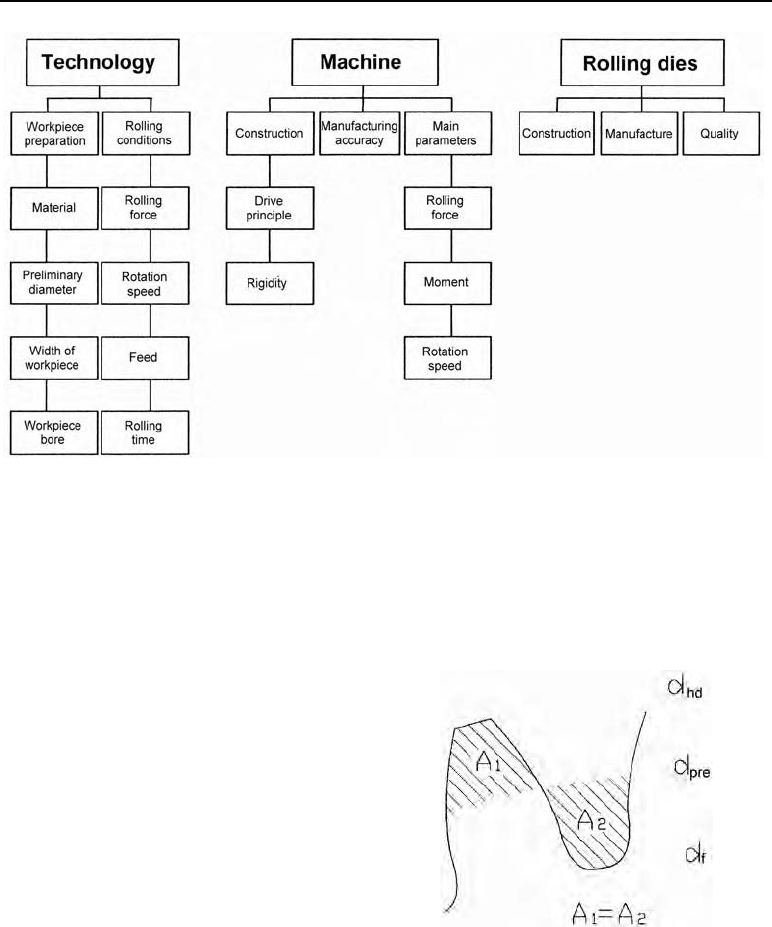
Figure 6.18 Factors which influence the quality of rolled parts
6.10.2 c) Establishing the theoretical pre-turning diameter d
pre
One crucial advantage of manufacturing gear tooth profiles by forming is the fact that there is
essentially no material loss.
The technician forming the part is confronted
with the task of defining initial forms with a
volume the same as that of the final form. The
quality of the rolled part which can be achie-
ved depends strongly upon the selection of the
theoretical pre-turning diameter d
pre
of the
rotationally symmetric starting form.
When this parameter is established by mathe-
matical / geometrical means, two main criteria
must be weighed up. On one hand, the pre-
turning diameter is worked out according to
the material displacement which takes place
during the forming process.
Figure 6.19 d
pre
if volume is constant
On the other hand, the calculation must also take into account the fact that the spacing rolled
on the external diameter of the blank is determined by the spacing of the addendum circle of
the rolling dies. If there are substantial differences between the theoretical pre-turning diameter
according to the volume and the value after the exact spacing is set down, repeated corrections
must be made.
72 6 Thread rolling
When determining the theoretical pre-turning diameter, the following formula can be used as a
basis:
hd p
pre n
(0.35)
2
dd
dm
Example:
The aim is to roll a helical gear with an involute flank profile out of C45 with the following
gear tooth parameters. Determine the theoretical pre-turning diameter of the rotationally sym-
metric starting stock.
m = 1.5875
D
= 25.75°
z = 10
d
hd
= 21.7 mm
d
p
= 14.9 mm
Solution:
pre
21.7 mm 14.9 mm 1.5875
(0.35) 18.92 mm
2 cos 25.75
d
q
6.10.3 Method and machines for rolling gear teeth
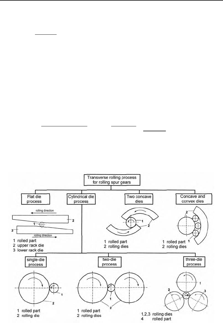
Figure 6.20 lays out the main rolling methods for the manufacture of gear teeth profiles by
forming.
Figure 6.20 Transverse rolling method for the production of gear teeth profiles
6.10 Methods and machines for rolling gears 73
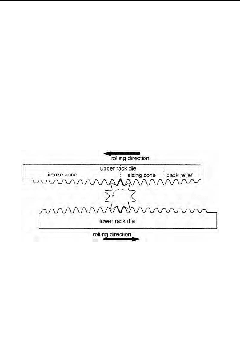
6.10.3 a) Rolling with the flat die method
The principle of rolling with flat dies (Figure 6.21) is a movement of the upper and lower dies
in opposite directions, in order to roll a defined profile onto a rotationally symmetric initial
form. In the rolling process which takes place, the geometry of the die is moulded onto the
workpiece (teeth) and involute flank profiles are formed.
At the start of the rolling process, the blank is held between drive centres. The upper and lower
dies move against one another in a translatory movement, simultaneously come into contact
with the workpiece and set the blank revolving by friction. The sloped intake zones of the dies
mean that the die teeth penetrate the workpiece to increasing depth with a continuous feed. At
the same time the material is displaced at the points of contact and flows into the spaces of the
die profile.
After the full-depth profile has been rolled at the end of the intake zone, the teeth are calibrated
in two further rolling revolutions to improve surface finish, the shape of the flanks and radial
runout. In the subsequent sloped die runout zone, the deformation forces ease off and the
rolled gear tooth system is removed.
Figure 6.21 The principle of the flat-die method with upper and lower rack dies
6.10.3 b) Rolling with the cylindrical die method
When transverse rolling with the cylindrical die method, the rotationally symmetric blank is
held in an axial direction between tooth tips. Two or three cylindrical dies (depending upon the
method used) shape the gear teeth on the blank, moving in the same direction and at a constant
rotation speed. The die teeth penetrate the workpiece by means of a radial shortening of the
distance between the axes of the cylindrical dies. This infeed motion is controlled hydraulically
or with a movable rolling die. The second cylindrical die is fixed. It must be possible to move
the workpiece holding device in the direction of the infeed movement so that the blank to be
centred during the deformation process. Another viable solution is rolling with a support gui-
de.
74 6 Thread rolling
In this variant, the axis of the workpiece is slightly below that of the rolling die in order to
prevent the blank from being pushed out during the deformation process.
As it is possible to re-roll several times, the rotary rolling method can be seen as a forming
process with an infinite die length.
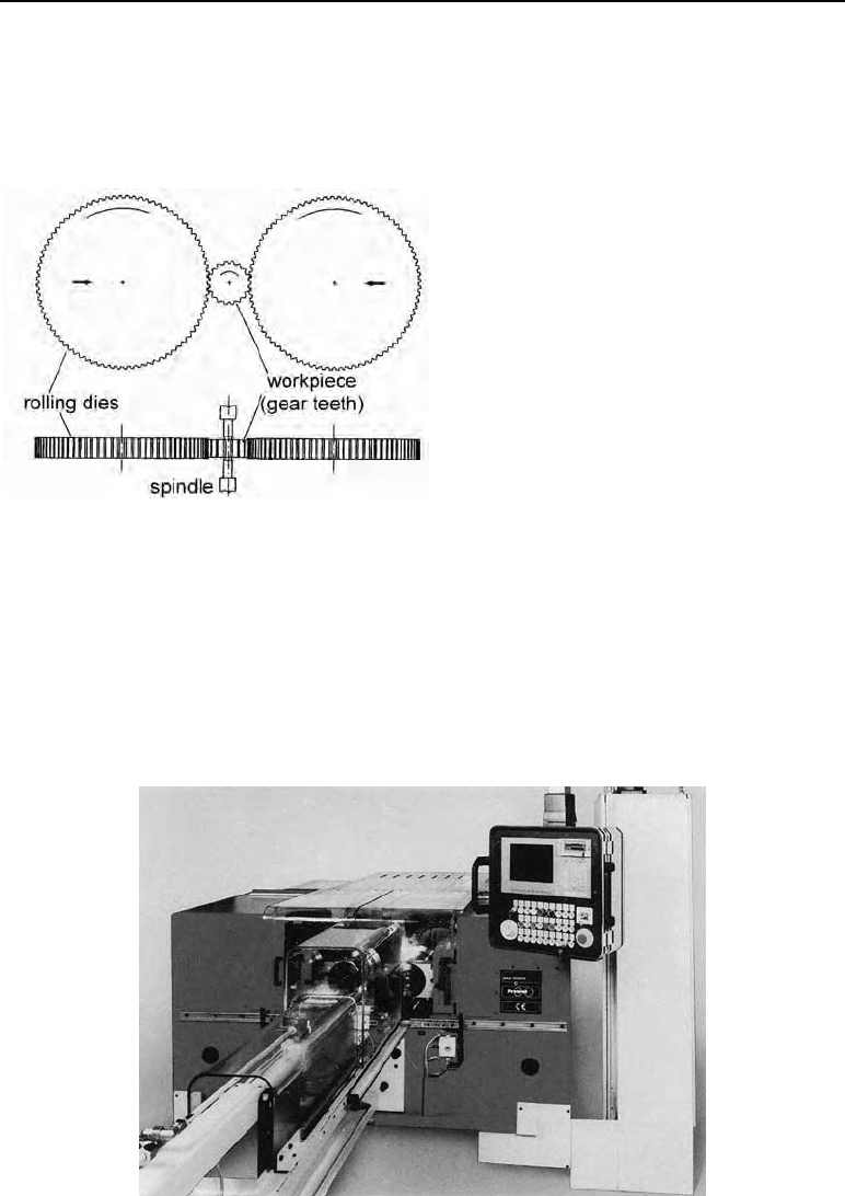
Figure 6.22
Principle of the cylindrical rolling
method with two rolling dies
The current state of technological standards mean that it is possible to roll good-quality gear
teeth with cylindrical dies up to a modulus of m = 1.5. When the modulus increases, the kine-
matic conditions involved in rolling mean that spacing, flank shape and symmetry defects
occur to a degree which has a substantial effect on the performance of the workpieces when in
use. Profile rolling machines using the cylindrical rolling method are basically designed with
either two or three dies. The design used most often in rolling gear teeth profiles is a machine
design following the proven two-roll principle (Figure 6.23) with two moving roller slides.
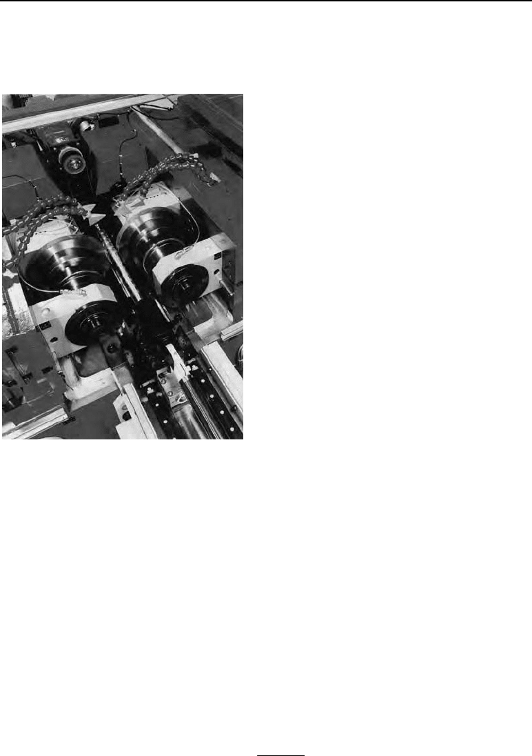
Figure 6.23 “Rollex” two-roll machine (Photograph from Profiroll Technologies works, Bad Düben,
Germany)
6.10 Methods and machines for rolling gears 75
Two main spindles, driven synchronously in the same direction, are used to take up the rolling
dies. One of the two rolling spindles is fixed, the other is moved mechanically or hydraulically
so that the rolling dies penetrate the rotationally symmetric blank.
Using CNC control it is possible to control
and visualise the processing of the values
involved in the rolling and their functions,
in a reproducible manner.
When rolling large profile depths with
cylindrical dies, forces of up to 800 kN can
be used in the deformation (PRZ80, Profi-
roll, Bad Düben, Germany). Gear tooth
profiles with a standard modulus are for-
med using forces in the region of 200 kN
depending on the workpiece.
Figure 6.24
The working area of a two-die machine (Profi-
roll Technologies, Bad Düben, Germany)
6.10.4 Rolling defects in processing
During the rolling process, the complicated kinematics mean that the following rolling defects
typical to the rolling of gear teeth profiles occur:
– undercut in the tooth root area of the gear,
– deviations in the shape of the flank,
– deviations in the flank alignment,
– spacing defects,
– deviations in radial runout.
Radial runout, spacing, flank shape and alignment affect the quality of the rolled part and the
optimising of the gear tooth profile.
6.10.4. a) Undercut in the gear tooth root area
Undercut occurs in the gear tooth root area if the tooth number limit, t
L
, is not reached in the
profile to be rolled.
– at an engagement angle of
D
0
= 20°:
L
2
0
2
sin
t
a

76 6 Thread rolling
The engagement and rolling interrelations mean that the addendum radius of the die profile
penetrates the target contour of the gear tooth root area, undercutting the usable involute
flank. The ensuing rolling defect is considered to be damaging if the load-bearing flank of
the tooth is undercut so much that it impairs the load-bearing capacity of the gear teeth dur-
ing gear engagement. This effect during rolling can be counteracted with a positive adden-
dum modification. The peak value of this addendum modification is limited by the forma-
tion of a peak on the top land of the gear tooth.
7 Cold hubbing
7.1 Definition
Cold hubbing is a cold bulk forming process where a hardened punch (male hub) penetrates a
workpiece at a low speed (slower than extrusion).
7.2 Application of the process
For the production of cavities in dies for moulding, stamping, injection moulding, plastic
moulding and drop forging.
For example:
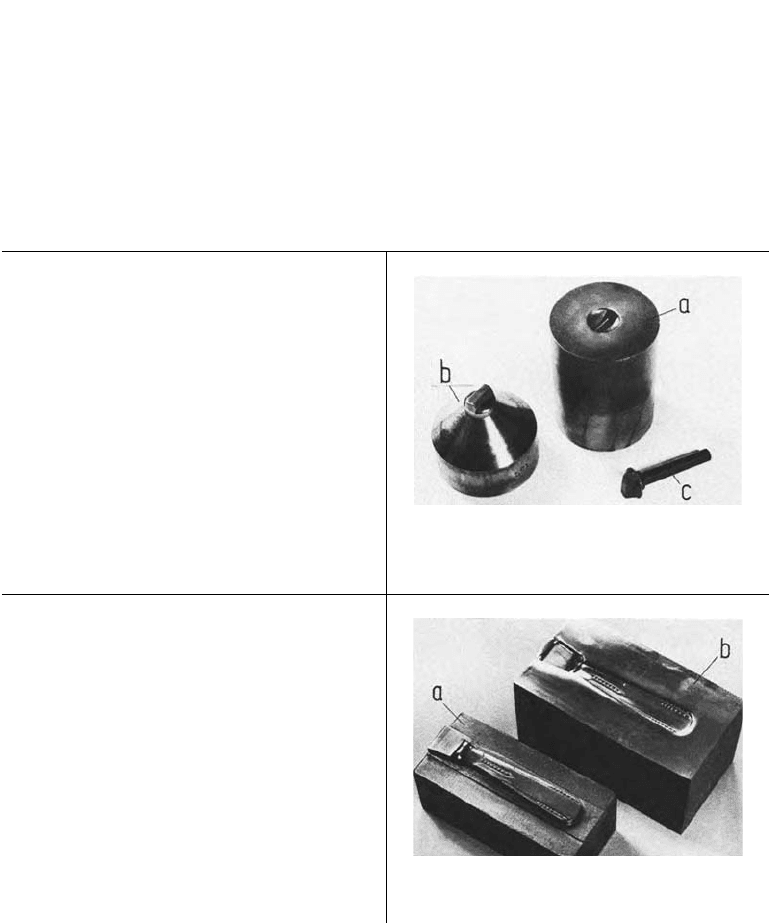
Screw and bolt production (Figure 7.1)
The hubbing of screw and bolt head shapes in
punches and dies.
Figure 7.1 a) cold hubbed bolt die, b) hub, c)
carriage bolt produced by upsetting
Production of cutlery (Figure 7.2)
The hubbing of cutlery cavities in stamping
dies.
Figure 7.2 Forging die for cutlery handle, a)
hub, b) hubbed stamping die
78 7 Cold hubbing
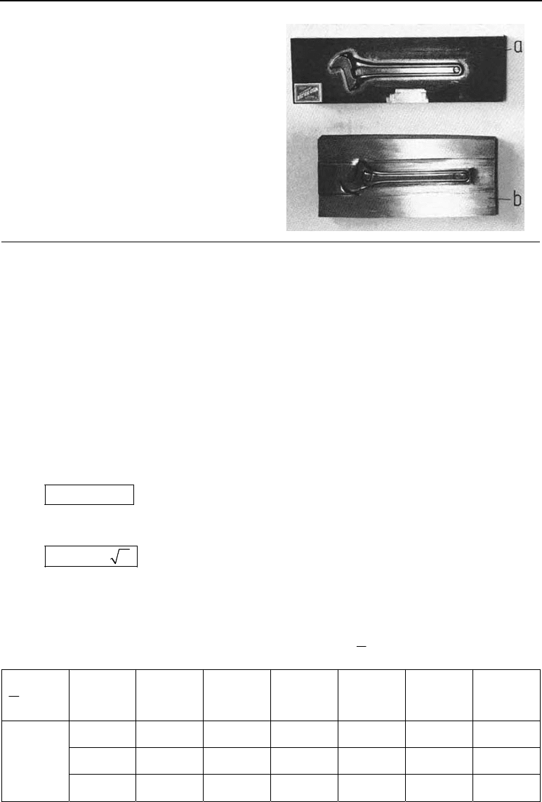
The production of forging dies (Figure 7.3)
Hubbing cavities in drop forging dies.
Fi
gure 7.3 Cold hubbed cavity in a drop forg-
ing die,
a) hub,
b) hubbed cavi
ty
7.3 Permissible deformations
The limits for cold hubbing are derived from the deformability of the tool steels and the per-
missible maximum surface pressure of the hub. As yet there is, however, no precise method of
calculation for this.
7.4 Calculation of force and mechanical work
7.4.1 Hubbing force
max
F
pA
equivalent diameter d
1.13 DA
F in N hubbing force
A in mm
2
hub area
d in mm diameter of the hub
t in mm hubbing depth
p
max
in N/mm
2
specific hubbing force
(from Table 7.1)
For hubs which are not round, an equivalent diameter d can be calculated from the hub area A.
Table 7.1 Specific hubbing force
2
max
in N/mm material and
t
pf
d
§·
¨¸
©¹
t
d
0.1 0.2 0.4 0.6 0.8 1.0
I
1700 2000 2300 2600 2800 2900
II
2400 2750 3200 – – –
Material
group
III
3100 [4000] – – – –

79
7.4.2 Hubbing work
WFt W in Nmm hubbing work
7.5 Materials which can be hubbed
Table 7.2 Steels which can be hubbed
Material
group
Quality Short desig-
nation
Material
number
Special notes on use
Screw and bolt tooling
I or II C 100 W 1
95 V 4
1.1540
1.2835
½
¾
¿
Heading punches and bottom dies for cold work
II III
X 32 CrMoV 3 3
X 38 CrMoV 5 1
45 CrMoW 5 8
X 30 WCrV 5 1
X 30 WCrV 9 3
1.2365
1.2343
1.2603
1.2567
1.2581
½
°
°
¾
°
°
¿
Heading punches and bottom dies for hot work
Drop forging tooling
II C 70 W 1
1.1520
II 45 CrMoV 6 7
X 32 CrMoV 3 3
1.2323
1.2365
Forging dies for light metals Forging dies for non-
ferrous heavy metals and for steels being pressed
III 55 NiCrMoV 6
56 NiCrMoV 7
1.2713
1.2714
½
¾
¿
Forging dies for steels being hammered
Die-casting tooling
I X 8 CrMoV 5
1.2342
Zinc pressure die-casting moulds
II 45 CrMoV 6 7
X 32 CrMoV 3 3
X 38 CrMoV 5 1
X 32 CrMoV 3 3
1.2323
1.2365
1.2343
1.2365
Zinc and light metal die-casting moulds Light metal
die-casting moulds Light-metal die-casting moulds
Brass die-casting moulds
Stamping dies
I or II II
C 100 W 1
90 Cr 3
1.1540
1.2056
½
¾
¿
Coining punches (minting)
½
¾
¿
Moulds for jewellery, electronic parts and furni-
ture mountings
II
III
45 CrMoV 6 7
55 NiCr 10
X 45 NiCrMo 4
X 165 CrMoV 12
1.2323
1.2718
1.2767
1.2601
(minting)
7.5 Materials which can be hubbed
80 7 Cold hubbing
7.6 Hubbing speed
Hubbing speeds are between
v = 0.01 mm/s and 4 mm/s
with higher-strength steels and difficult shapes needing to be hubbed at the lower hubbing
speed.
7.7 Lubrication during hubbing
To prevent cold welding between the hub and the workpiece, the following measures are nec-
essary:
– The surfaces of the hub which come into contact with the workpiece must be polished.
– Brush the hub surface with copper sulphate solution (acts as a lubricant binder).
– Lubricate with molybdenum disulphide (MoS
2
).
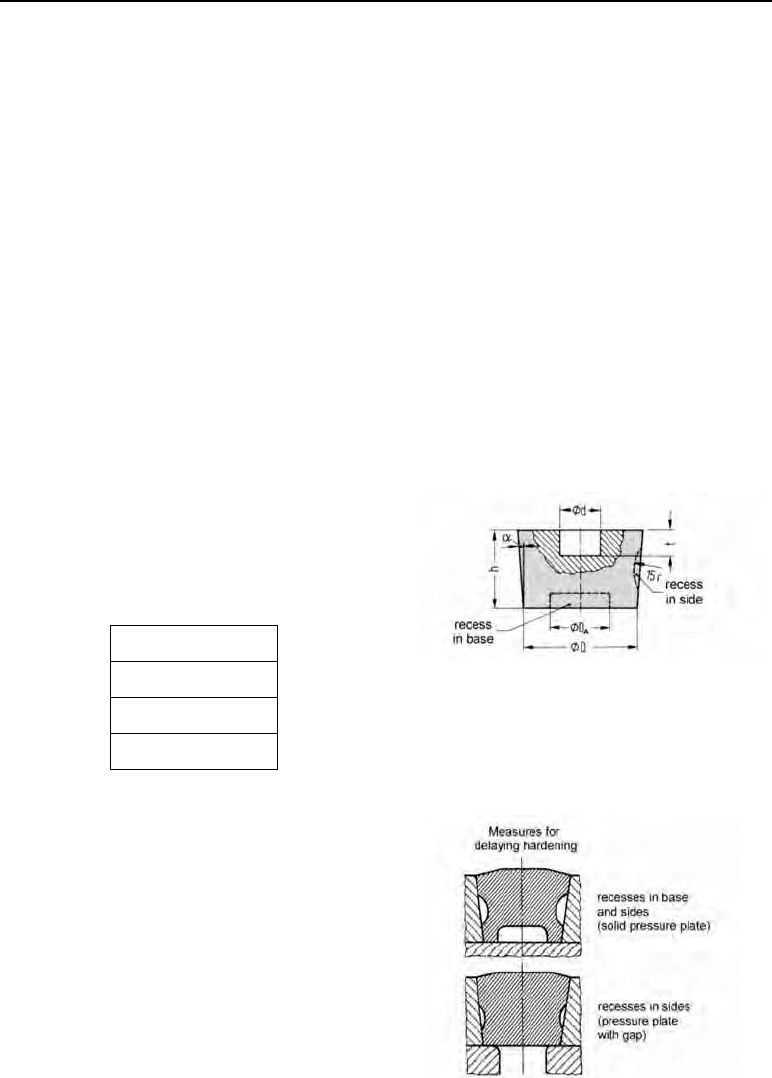
7.8 Characteristics of the workpieces to be hubbed
– For the workpieces which are to be hubbed,
their external diameter and their height must
be in relation to the hubbing diameter and
the hubbing depth.
2.5 Dd
1.5
A
Dd
2.5 htt
1.5 to 2.5
D
q
– The workpiece to be hubbed needs to have
recesses in its sides and base. This makes the
material flow easier and the hubbing capacity
higher.
Figure 7.4 Measurements of the workpiece to be
hubbed
d hubbing diameter, t hubbing depth, D external
diameter, D
A
recess in the base, r radius for the
recesses in the sides, D slope angle # 1°
Figure 7.5 Recesses in the workpiece