Tsch?tsch H., Koth A. Metal Forming Practise: Processes - Machines - Tools
Подождите немного. Документ загружается.

6.6 Rolling dies 61
6.5 Rolling speeds with cylindrical dies
Rolling speeds are between 30 and 100 m/min depending upon the material to be rolled.
6.6 Rolling dies
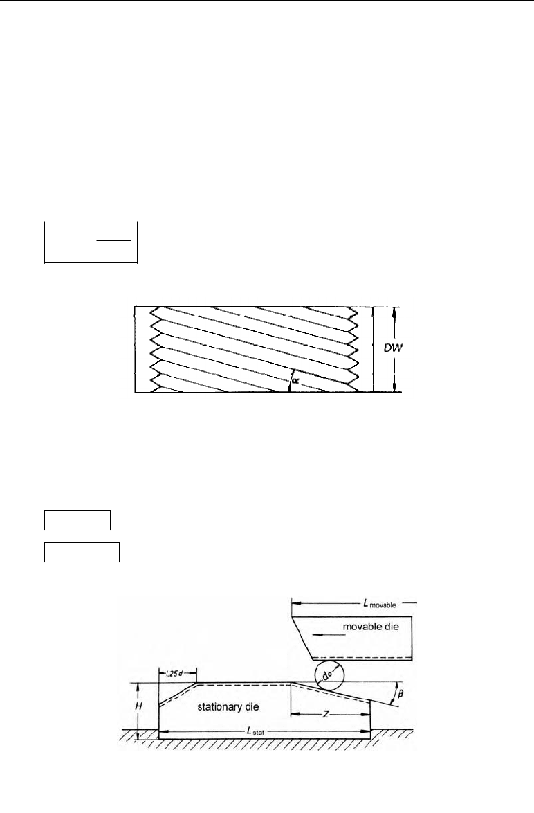
6.6.1 Flat dies
The profile of the flat dies is that of the thread to be produced. The slope of the grooves corre-
sponds to the pitch angle of the thread.
p
tan
h
d
D
S
h in mm thread pitch
d
p
in mm pitch diameter
Figure 6.8 The shape of the grooves on a flat die
There are various designs as regards the shape of the thread rolling dies. Here, a common sha-
pe is shown.
0
3zd
3to7
E
q
d
0
in mm initial diameter
E
in degrees angle of intake zone
z in mm intake zone length
Figure 6.9 Dimensions and arrangement of the flat dies

62 6 Thread rolling
The thread profile is also fully deep in the intake area.
The length of the die should be at least 15 d
0
.
The movable die should be 15 to 20 mm longer than the stationary die.
The die width DW
1
3DW L h
DW in mm die width
h in mm thread pitch
L
1
in mm length of the thread on the workpiece
H in mm die thickness
L in mm die length
Table 6.3 Die dimensions for metric threads
Die length in mm
Nominal thread
diameter
movable
L
m
fixed
L
f
Die width
DW
in mm
Die thickness
H
in mm
Intake length
z
in mm
M 6
125 110 40 25 20
M 10
170 150 45 30 28
M 16
250 230 65 45 46
Table 6.4 Tool materials for flat dies and rollers
Material no.
1.2379 1.2601 1.3343
HRC assembly hardness 59 to 61 59 to 61 60 to 61
6.6.2 Dimensions of the rolling dies
– Infeed method (screw threads)
pp pp
;/ /
FL
Dd DdFLflk
fl
pp
Dkd
ex p
Dkdt

6.7 Example 63
D
p
in mm pitch diameter of the rollers
d
r
in mm pitch diameter of the thread to be rolled
D
ex
in mm external diameter of the roll
t in mm thread depth
FL by number number of flights on the die
fl by number number of flights on the thread
k factor which depends upon the ratio of FL/fl
– Through-feed method with rolling grooves without a pitch
In the through-feed production method, the diameter of the roller does not depend upon the
diameter of the thread to be produced. For this reason it is generally selected according to
the dimensions of the machine.
– Combined infeed-through-feed method
W
p
p
W
sin
sin( )
Dkd
D
DH
D
w
= pitch angle of the workpiece thread
H
= swivel angle of the die axes
Table 6.5 shows common rotary die materials and the corresponding assembly hardnesses.
Rotary die life depends upon the strength of the material to be rolled.
Table 6.5 Tool lives of rotary dies
Material strength R
m
in N/mm
2
Number of units per tool
1000
800
600
100000
200000
300000
6.7 Example
The aim is to produce threads of M10 x 50 long.
Calculate the initial diameter required.
Solution:
d
0
= d – 0.67 · h = 10 mm – 0.67 · 1.5 mm = 9.0 mm
h = 1.5 mm from the table.
64 6 Thread rolling
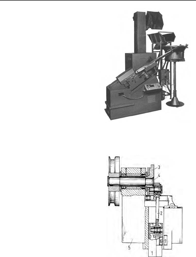
Figure 6.10
Automatic high-performance thread rolling ma-
chine, type R 2 L (Photograph from Hilgeland
works, Wuppertal, Germany)
6.8 Thread rolling machines
Here, a difference is made between:
Flat die thread rolling machines
Thread rolling machines with cylindrical dies
Thread rolling machines with cylindrical and
segment dies.
6.8.1 Flat die thread rolling machines
The basic concept behind the construction
of these machines is practically the same for
all manufacturers. The standard is built as a
box-shaped cast construction or, as in the
machine shown in Figure 6.10, a combina-
tion of welded and cast construction. A slide
takes up the movable die. The slide guide is
mostly designed as an adjustable prism or
V-block. The rolling slide (Figure 6.11) is
driven by the crank wheel (3) located on the
crankshaft, via the connecting rod (2). The
smooth running of the machine is achieved
by means of the pulley, which is designed
as a flywheel.
The workpieces are sorted using a trommel
(Figure 6.10) or an oscillating conveyor and
guided into the working area by hardened
conductor tracks. A pusher (Figure 6.1)
controlled by cams brings the blank be-
tween the rollers.
The number of pieces per time unit which
can be produced using these machines is
shown in Table 6.2.
Flat die thread rolling machines are used
mainly in the screw and standard part in-
dustry.
Figure 6.11
The drive of a flat die thread rolling machine of
the Hilgeland company. 1 slide, 2 connecting
rod, 3 crank wheel, 4 crankshaft, 5 standard, 6
moving flat die, 7 fixed flat die
6.8 Thread rolling machines 65
6.8.2 Cylindrical-die thread rolling
When rolling with cylindrical dies, feed is provided by rotation and the motion of the tools.
Both dies are powered. The rolling slide moves longitudinally, carrying one roller and provid-
ing the rolling force; it is hydraulically driven. Both the speed of movement and the force of
the hydraulic lifting piston can be controlled with great precision using the CNC control.
Whereas conventional machines work on a power-controlled basis, in CNC machines the proc-
ess takes place in a closed loop, based on feed, i.e. penetration depth and material displacement
are co-ordinated for every workpiece revolution. This means that material displacement is no
longer influenced by the force which builds up, but can be deliberately controlled. This allows
the calculation of
rolling time
distribution of force and
distribution of moment
from the influencing factors involved in the deformation process, e.g:
rolling method, profile shape, material, stock dimensions, degree of rolling, tool geome-
try and lubrication
with fairly high certainty.
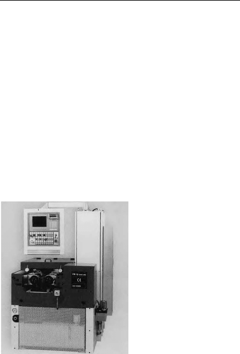
The CNC-controlled thread rolling machine shown in Figure 6.12 is built in six different sizes
from 100-1000 kN of rolling force.
Figure 6.12
PW10 CNC/AC thread rolling machine
(Photograph from the Profiroll Tech-
nologies GmbH works, Bad Düben,
Germany)

66 6 Thread rolling
The machine body is built as a C-frame and its open top guarantees good access to the wor-
king area. The rolling process can be precisely controlled by the latest proportional valve
and drive technology combined with the three-axis CNC control. The graphic user interface
allows fast, uncomplicated operation of the machine. The graphical representation of the
process includes the most important parameters of the method, such as force and torque, in
the curves for planned slide and spindle movement, which means that the rolling process
can be optimised.
The data management system provides all the comforts of comprehensive data organisation.
It also means that repeat orders can be processed with very little preparation.
In the thread rolling machine pictured in Figure 6.13, the standard is also produced as a box
construction which is bend- and torsion-resistant.
Figure 6.13
RTW 30x CNC/AC thread
rolling machine
(Photograph from Roll-
walztechnik Abele + Höltich
GmbH works, Engen, Germany)
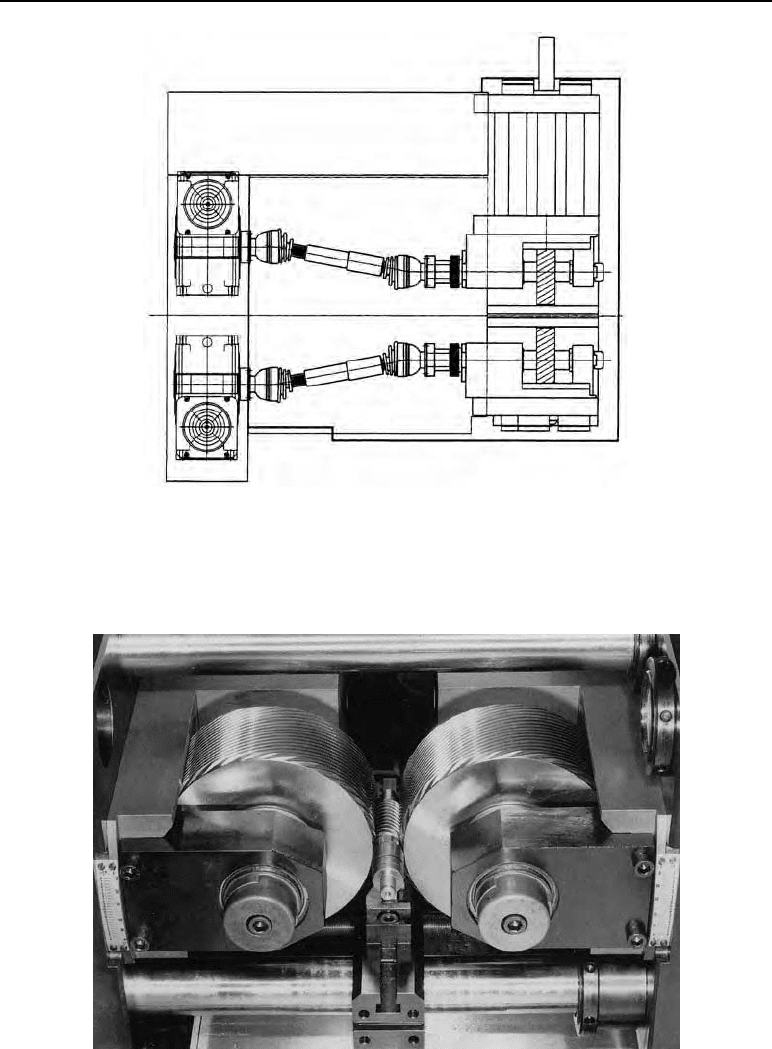
The rolling spindle (Figure 6.14) is driven by two three-phase servomotors via propeller
shafts. The rotation speed is controlled with frequency converters. The angles of both die
axes can be adjusted from 7-10.
The longitudinally-moving roller slide which provides the rolling force is operated hydrau-
lically. The hydraulic piston can be delicately controlled by the CNC control in terms of
both rolling force and speed of movement. The position and control signals are transferred
and supervised in connection with an incremental measuring system. The crucial innovation
in this control concept is that the track of both rollers towards one another is adjusted by
pressing keys. The value ascertained is saved and constantly monitored during the rolling
process. The saved values can also be retrieved for new workpieces with similar technical
data, thus saving preparation time.
Figure 6.15 shows the rolling process with the workpiece inserted.
6.8 Thread rolling machines 67
Figure 6.14 Drive layout of the rolling dies and rolling slide (Photograph from Rollwalztechnik Abele +
Höltich GmbH works, Engen, Germany)
Figure 6.15 Rolling dies and workpiece during the rolling process (Photograph from Rollwalztechnik
Abele + Höltich GmbH works, Engen, Germany)

68 6 Thread rolling
The following table shows some technical data for the kind of thread rolling machines on the
market today.
Table 6.6 Technical data for the thread rolling machines
Rolling force in kN
80 - 1000
Rolling spindle diameter in mm
28 - 100
Uptake length of the rolling spindle in mm
80 - 300
Diameter of cylindrical die in mm
70 - 235
Workpiece diameter in mm
2 - 120
Rolling times in s
1 - 120
Drive capacity (rolling spindle motor) in kW
2.5 - 30
Range of application of thread rolling machines with cylindrical dies
These machines can be used for
the infeed method,
the through-feed method and
the combined infeed-through-feed method.
Because of this they are used to produce:
– special high-precision screws
– very strong waisted-shank bolts
– single and multi-thread worms
– trapezoidal threads and ballscrew spindles
– knurling work.
6.9 Exercise on Chapter 6
1. What methods of thread rolling are there?
2. Which method is used to produce long, deep threads?
3. What are the advantages of thread rolling?
4. What kinds of thread rolling machines are there?
6.10 Methods and machines for rolling gears 69
6.10 Methods and machines for rolling gears
6.10.1 Introduction
Gear rolling is gaining in importance due to its technical advantages as a method, such as:
– high achievable surface finish,
– increase in strength due to work hardening,
– high load capacity due to adapted grain structure,
– short processing times and high reproducibility,
– economic use of material due to chipless production,
– low deformation forces due to only partial deformation.
6.10.2 Gear rolling
A principal difference is made between the following different methods when transverse roll-
ing gears:
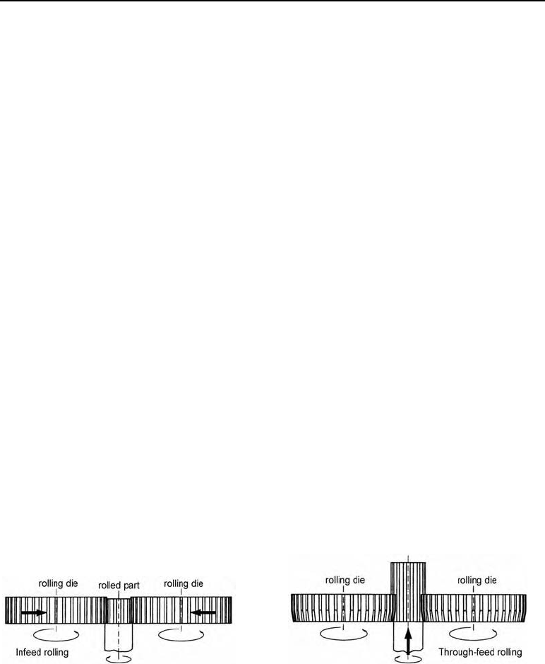
1. Infeed rolling: The rolling dies penetrate into the rotationally symmetric blank by a reduc-
tion in their radial axis distance, forming the profile by the rolling kinematic of the tool and the
workpiece.
2. Through-feed rolling: In this process the rolling dies move across the entire length of the
gear to be rolled in an axial direction, their centres at a constant distance. The centre distance
is defined by the gear tooth parameters of the workpiece profile (root circle and addendum
circle diameters). In this process, as opposed to pure transverse rolling, part of the deformation
forces must also be applied in the longitudinal direction, so the rolling dies must have sloped
intakes. Their slope angle establishes the relationship between the axial and radial material
flow.
Figure 6.16 Comparison of the infeed rolling and through-feed methods with cylindrical dies
A combination of both methods is used in thread rolling. In this combined version, the infeed-
through-feed method, the rolling dies are set up with a smaller pitch angle than the gear teeth
to be cut. Feeding in the dies provides the axial thrust and equals out the pitch difference be-
tween the die and the workpiece.
70 6 Thread rolling
6.10.2 a) Interrelations during rolling
In transverse rolling, the shape of the workpiece is created by a rolling motion between the die
profile and the involute flank of the gear tooth.
In this process the mechanised feed motion makes the rolling dies penetrate the workpiece,
with direction and speed adjusted depending upon the diameter, causing the material to flow
into the profile space on the die. This process continues until the required gear tooth parame-
ters are obtained (root circle and addendum circle diameter).
When the constructional setup of the rolling tooling is planned mathematically, the constantly
changing kinematic rolling interrelations from the penetration of the die teeth into the work-
piece must be taken into account.
The process means that the material flow is asymmetric, causing the flanks of the teeth to devi-
ate in shape from that intended; this can be counteracted by controlled reversing (change of
rolling die direction during the cylindrical rolling process) which swaps the flank coast and
drive sides.
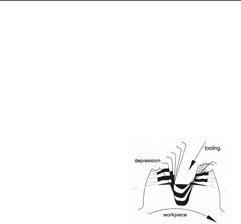
The de
p
ression which forms along the top
land of the tooth when gear teeth are rolled
has no effect on the gear tooth function, as the
quality of an involute tooth shape is defined
by its load-bearing flank. A comparison o
f
target and actual values of the geometry of the
rolled gear after trial rolling should be drawn
upon when correcting the rolling tools.
Figure 6.17 Interrelations during rolling
6.10.2 b) Influencing factors when rolling gear teeth
In Figure 6.18 the main influencing factors on the adequate quality of rolled parts are shown.
They have been divided into technological/machine-related factors and those related to con-
struction/mathematics. The design and construction of the rolling tools for the deformation
process must be mathematically precise for the method to achieve the necessary quality. The
quality depends upon the complicated kinematic relationship between the rolling die and the
workpiece, as well as a mastering of the typical problems associated with the rolling method.