Tsch?tsch H., Koth A. Metal Forming Practise: Processes - Machines - Tools
Подождите немного. Документ загружается.

9 Ironing (wall ironing)
9.1 Definition
Ironing is a bulk forming process where the
deformation force (tensile force) must be ab-
sorbed by the cup wall which is deformed. If
the stress in the formed cup wall exceeds the
tensile strength of the cup material, the base is
torn off.
9.2 Application of the process
For the production of flanged hollow parts
whose base is thicker or thinner than the wall.
With this method, hollow parts with inner
tapering can also be produced.
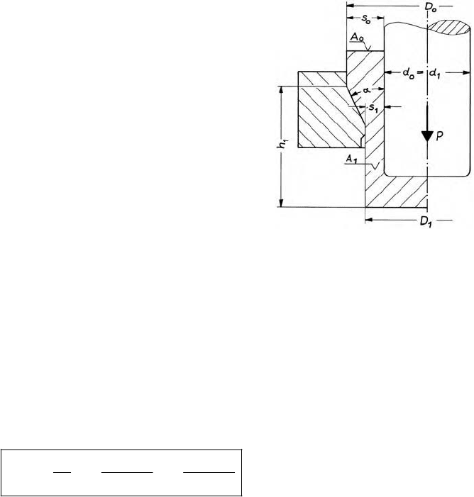
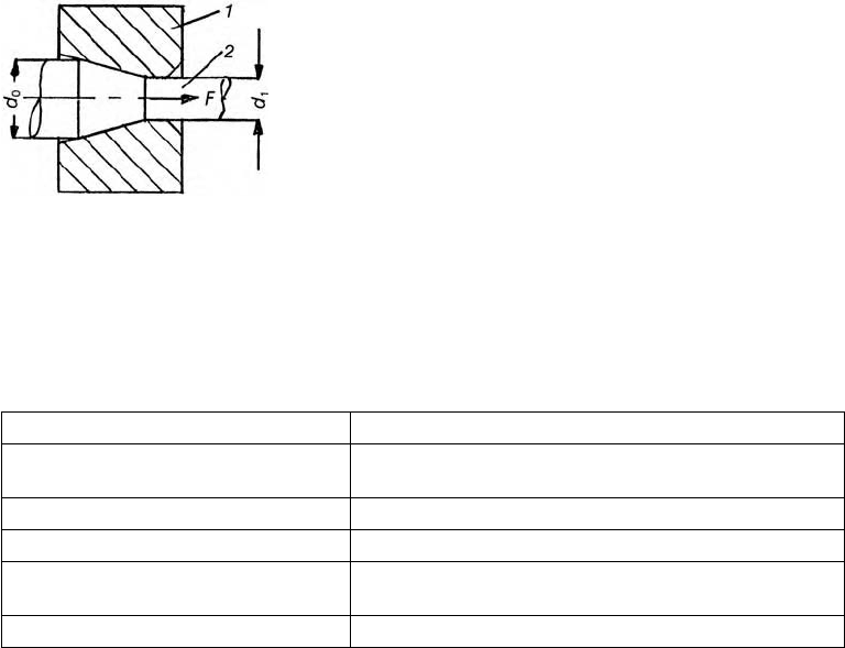
Figure 9.1 Cup with flange.
Ironing with a ring
9.3 Starting stock
The starting stock is a pre-formed (mainly produced by extrusion), thick-walled cup.
9.4 Principal strain (Figure 9.1)
22 22
0
00 00
p
22 22
1
10 11
ln ln ln
Dd Dd
A
A
Dd Dd
M
A
0
in mm
2
ring area before forming
A
1
in mm
2
ring area after forming
D
0
in mm external diameter before forming
d
0
in mm inside diameter before forming
D
1
in mm external diameter after forming
d
1
in mm inside diameter after forming (usually d
0
= d
1
)
M
p
– principal strain
92 9 Ironing (wall ironing)
If
M
p
is provided and the limiting diameter D
1
is sought where d
0
= d
1
= const., then:
p
22
00
2
1
0
.
Dd
Dd
e
M
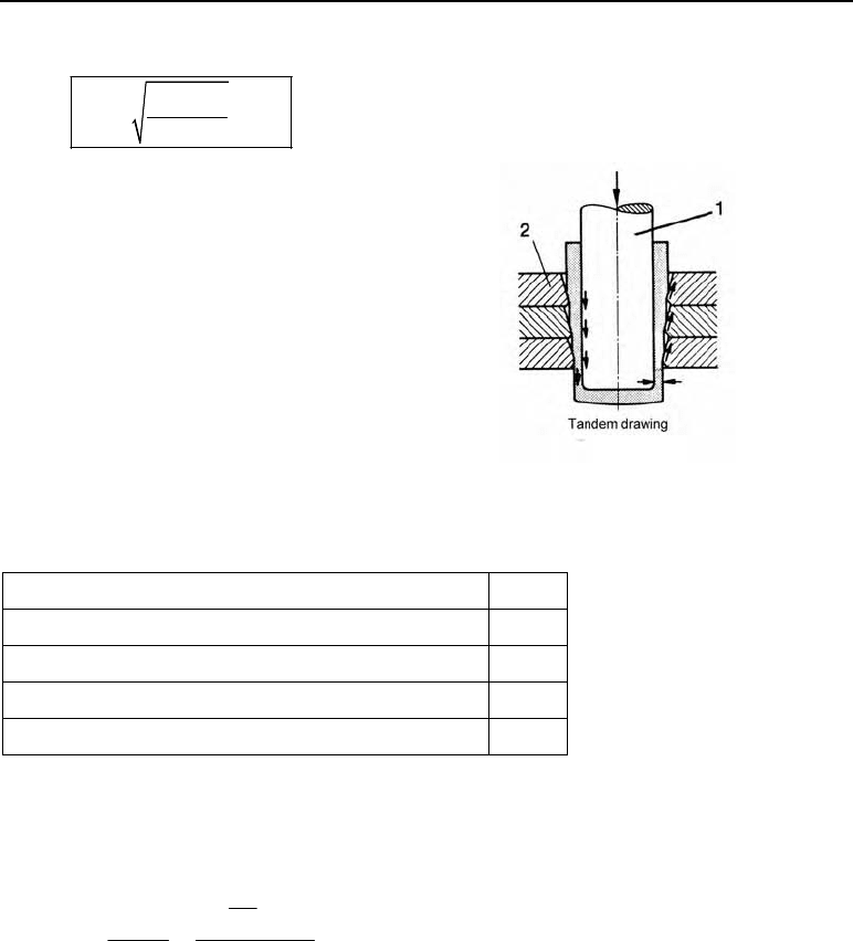
During ironing with a die ring (Figure
9.1), the values provided in Table 9.1
are permissible. When ironing with
several die rings arranged one after the
other (Figure 9.2), approx. 20% more
deformation can be allowed (e.g. not
35% but 40%).
Figure 9.2 Multiple ironing. 1 punch, 2 die ring
Table 9.1 Permissible deformations with a die ring
Material
M
p
perm
Al 99.8; Al 99.5; Al Mg 1; Al MgSi 1; Al Cu Mg 1
0.35
Cu Zn 37(Ms 63)
0.45
Ck 10 – Ck 15,Cq 22 – Cq 35
0.45
Cq 45; 16 Mn Cr 5; 42 Cr Mo 4
0.35
The number of ironing operations required can be determined from the quotients of actual and
permissible deformation.
Number of ironing operations required:
perm
perm
0
p
n
pp
ln 100
A
A
n
M
MM
§·
¨¸
©¹
n number of ironing operations required
A
0
in mm
2
cross-sectional area before the first operation
A
n
in mm
2
cross-sectional area after the last (nth) operation
M
p
perm
in percent permissible deformation
M
p
in percent principal strain.
The actual limiting values, however, result from the ironing force. This must remain lower
than the product of the ring area A
1
after forming and the strength of the material.
1e 1m
F
AR AR
esmB
( previously previously ).RR
VV
9.6 Example 93
If F > A
1
· R
e
: then a further, undesired deformation occurs.
If F > A
1
· R
m
: then the cup tears off near the base.
9.5 Calculation of force and mechanical work
9.5.1 Force
m
p
1str
3
F
10
Ak
F
M
K
F in kN ironing force
A
1
in mm
2
cross-sectional area after forming
k
str
m
in N/mm
2
mean flow stress
M
p
– principal strain
K
F
– deformation efficiency
10
3
in N/kN conversion factor
9.5.2 Mechanical work
1
WFhx
W in kN m mechanical work
h
1
in m punch displacement
x – process factor (x = 0.9).
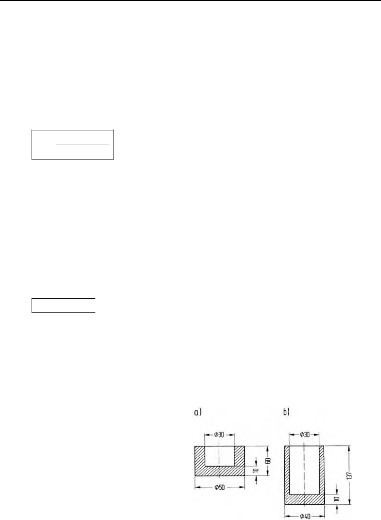
9.6 Example
The aim is to form a thick-walled pre-
formed cup into a cup with reduced wall
thickness (Figure 9.3).
Where: material Cq 45;
K
F
= 0.7.
Find:
1. principal strain
2. number of ironing operations
3. smallest possible diameter for the first
operation (
M
pperm
= 35 %)
4. force for the first operation
Figure 9.3 Ironed workpiece.
a) blank í pre-formed cup,
b) finished part after three operations
94 9 Ironing (wall ironing)
Solution:
Principal strain:
22
2222
00
p
22 22 22
10
50 mm 30 mm
ln ln 0.82.
40 mm 30 mm
Dd
Dd
M
Number of ironing operations required:
perm
p
p
82 %
2.34
35 %
n
M
M
n = 3 operations required.
(Repeated soft annealing required after each operation.)
Smallest possible diameter for the first operation:
h
22
2222
00
2
2
1
0
0.35
50 mm 30 mm
30 mm
Dd
Dd
ee
M
1min
1600
900 45 mm .
1.419
D
Force for the first operation:
For
M
p
= 35 %: k
str
0
= 390 N/mm
2
; k
str
1
= 860 N/mm
2
; k
str
m
= 625 N/mm
2
.
During the first operation, D
1
= 45 mm, d
0
= d
1
= 30 mm
mm
22
1 str p str p
10
33
FF
()
10 4 10
Ak D d k
F
M
SM
KK
2222 2
3
(45 mm 30 mm ) ʌ 625 N/ mm 0.35
276 kN .
40.710
F
9.7 Exercise on Chapter 9
1. How does ironing differ from forward extrusion?
2. What limits the extent of the deformation?
3. What workpiece shapes is it used for?
10 Wire drawing
10.1 Definition
Wire drawing is a form of drawing using a sliding action (Figure 10.1) where a wire of a larger
size (d
0
) is pulled through a drawing ring of a smaller size (d
1
). In this process the wire is
given the shape and the cross-sectional dimensions of the drawing ring. Wire drawing belongs
to the production processes which involve forming by tensile and compressive forces, as a
state of stress develops in the deformation zone due to deformation by both tension and pres-
sure. In wire drawing, a difference is made according to the dimensions of the wire between:
coarse drawing: d = 16 to 4.2 mm
medium drawing: d = 4.2 to 1.6 mm
fine drawing: d = 1.6 to 0.7 mm
ultra-fine drawing: d < 0.7 mm
and according to the machine used, between:
single-draft drawing
tandem drawing.
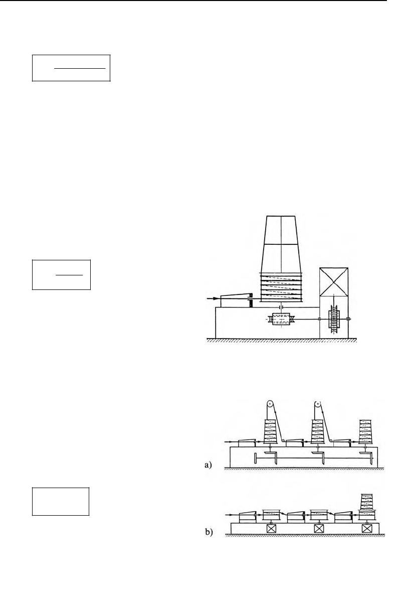
Figure 10.1 The principle of wire drawing.
1 die, 2 wire
10.2 Application
Wire and rod drawing are used to produce wires and rods with smooth surfaces and low toler-
ances for various fields of application (Table 10.1).
Table 10.1 Fields of application of drawn wires and rods
Material Application
Low-carbon steels, C 10 – C22
Wires, wire meshes, barbed wire, pins, nails, screws and
bolts, rivets
High-carbon steels (up to 1.6% C) Rod material for automatic processing, wire cables
Alloy steels Industrial springs, welding wires
Copper and copper alloys
Wires, wire meshes, screws, bolts and shaped parts, parts
for the electrical industry
Aluminium and Al alloys Screws and bolts, shaped parts, electrical lines, etc.
96 10 Wire drawing
10.3 Starting stock
The starting stock for wire drawing is hot-rolled wires. For rod drawing, rods produced by hot
rolling or extrusion moulding are used as starting stock.
10.4 Principal strain
The principal strain results from the aspect ratio before and after drawing.
p
0
1
ln
A
A
M
p
0
1
/2
d
d
e
M
A
0
in mm
2
cross-section before drawing
A
1
in mm
2
cross-section after drawing
d
0
in mm diameter before drawing
d
1
in mm diameter after drawing
e = 2.718 basic number of the natural logarithm
M
p
principal strain
10.5 Permissible deformations
The following table contains standard values for the drawing reductions and the permissible
total deformation in tandem drawing.
Table 10.2 Permissible deformations with tandem drawing
Mate-
rial
Intake strength
R
m
in N/mm
2
Intake diameter
d
0
in mm
Drawing reduc-
tion between
two draws
M
p
perm
(%)
Total deformation
(tandem drawing)
M
p
perm
(%)
Number of
drawing sta-
tions
400 4 – 12 18 – 22 380 – 400
1200 4 – 12 18 – 22 380 – 400
Steel wire
1200 0.5 – 2.5 12 – 15 120 – 150
8
to
21
8 – 10 wet draws
40 – 50 350 – 400
Cu
materi-
als
Cu (soft)
250
1 – 3.5 18 – 20 200 – 300
5
to
13
12 – 16 wet
draws
20 – 25 250 – 300
Al mate-
rials
Al (soft) and
Al alloy
80
1 – 3.5 15 – 20 150 – 200
5
to
13

10.7 Drawing speeds 97
In single drawing, the permissible deformations are around:
– Steel wires = 150 – 200 %
– Cu materials = 200 %
(Cu soft)
– Al materials = 200 %
(Al soft).
10.6 Drawing force
According to Siebel, the drawing force can be calculated with the following equation
m
p
dr 1 str
p
2
1.
3
FAk
PD
M
DM
§·
¨¸
¨¸
©¹
The mean coefficient of friction is around
P
= 0.035 (
P
= 0.02 to 0.05). The optimum drawing
angle, requiring the least force, is around 2
D
= 16º. From this it follows for the angle in radi-
ans:
80.13
180 180
SS
DD
q q
qq
.
If these values are brought into the above equation, then the drawing force during wire draw-
ing can be determined approximately with the simplified equation and the deformation effi-
ciency
K
= 0.6.
m
1 str p
dr
F
Ak
F
M
K
F
dr
in N drawing force
k
str
m
in N/mm
2
mean flow stress
A
1
in mm
2
cross-section of the wire after drawing
M
p
– principal strain
K
F
– deformation efficiency (
K
F
= 0.6).
10.7 Drawing speeds
10.7.1 Single-draft drawing
The drawing speeds for single-draft drawing can be taken from the following table.
98 10 Wire drawing
Table 10.3 drawing speeds
X
for single-draft draws
Material Intake strength R
m
in N/mm
2
X
max
in m/s
(iron wire)
400
20
800 15
Steel wire
1300 10
Cu (soft)
250
Brass, bronze
400
20
Al and Al alloys
80 – 100 25
10.7.2 Tandem drawing
In tandem drawing, the drawing speed differs at every drawing. As the volume is constant, the
speed is higher when the wire cross-section is reduced.
X
1
· A
l
=
X
2
· A
2
X
1
· A
l
=
X
n
· A
n
nn
1
1
A
A
X
X
X
1
in m/s drawing speed at the first draw
X
2
in m/s drawing speed at the 2
nd
draw
X
n
in m/s drawing speed at the nth draw
A
1
in mm
2
wire cross-section after the 1
st
draw
A
2
in mm
2
wire cross-section after the 2nd draw
A
n
in mm
2
wire cross-section after the nth draw
In tables of standard values, the highest speeds, applying to the last drawing, are always listed
for tandem drawing machines.
Table 10.4 Drawing speed
X
n
for tandem drawing
Material Intake strength R
m
in N/mm
2
X
n
in m/s
(iron wire)
400
20
800 15
Steel wire
1300 10
Cu (soft)
250
Brass, bronze
400
Al (soft), Al alloys
80 – 100
25
10.8 Drive power 99
The block rotation speed n may then also be calculated from the drawing speed which corre-
sponds to the block peripheral speed involved.
60 s/ min
n
d
X
S
X
in m/s drawing speed
d in m block diameter
n in min
–1
block rotation speed
10.8 Drive power
The drive power of the wire drawing machine is determined from the drawing force and the
drawing speed.
10.8.1 Single-draft drawing machine
(Figure 10.2)
dr
M
F
P
X
K
P in kW drive power
F
dr
in kN drawing force
X
in m/s drawing speed
K
M
efficiency of the machine
(
K
M
= 0.8).
Figure 10.2 The principle of the single-draft
drawing machine
10.8.2 Tandem drawing machine (Fig-
ure 10.3)
With tandem drawing machines, the total
drive power results from adding together the
power required for each draw.
M
PP
¦
Figure 10.3 The principle of the tandem drawing machine.
Wire feed:
a) from above with two loops,
b) longitudinally without redirection
100 10 Wire drawing
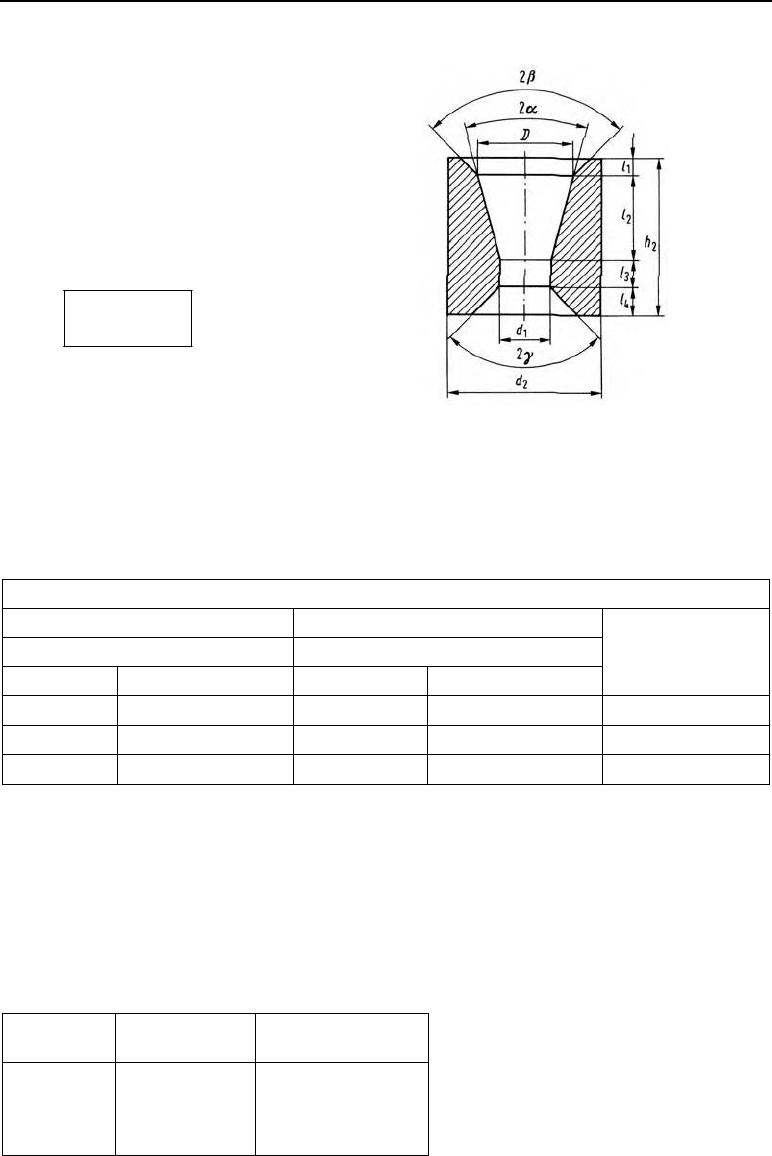
10.9 Drawing tooling
The drawing die (Figure 10.4) consists o
f
three zones. These are the cone-shaped intake
with the entry angle 2
E
and approach angle 2
D
, the bearing land l
3
and the cone-shaped
back relief l
4
with the back relief angle 2
J
.
The length of the cylindrical guide bush l
3
is
around:
31
0.15ld
The approach angle 2
D
influences the draw-
ing force and the surface finish of the wire.
Table 10.5 shows optimum values.
Figure 10.4 Designations of the angles and
measurements on the drawing die.
Table 10.5 Optimum approach angle 2
D
depending upon the material, the extent of deformation and the
type of drawing.
Approach angle 2
D
Material Material
Steel (C < 0.4 %), brass, bronze Steel (C > 0.4 %)
Wet draw Dry draw Wet draw Dry draw
M
p
in %
11º 9º 10º 8º 10
16º 14º 15º 12º 22
19º 17º 18º 15º 35
10.9.1 Drawing die materials
Drawing dies are produced from steel, carbide and diamonds.
Steel drawing dies
Table 10.6 Steels and assembly hardnesses for steel drawing dies
Material HRC working
hardness
Fields of application
1.2203
1.2453
1.2080
1.2436
63 – 67
Rod and tube drawing