Tsch?tsch H., Koth A. Metal Forming Practise: Processes - Machines - Tools
Подождите немного. Документ загружается.

10.9 Drawing tooling 101
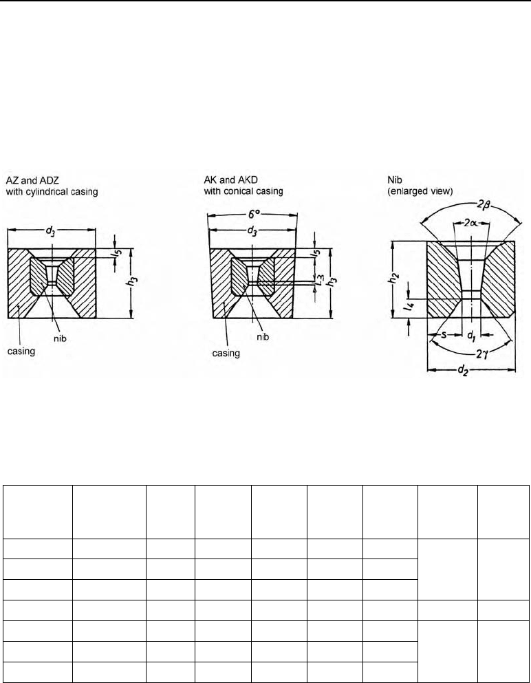
Carbide drawing dies (Figure 10.5)
Lower-diameter wires are nearly always drawn with dies made of sintered carbides.
For this purpose, the carbide application groups G10 to G60 are used (the lower the number, the
higher the hardness).
Table 10.7 shows the dimensions of carbide drawing dies (Figure 10.5) and the corresponding
steel reinforcement.
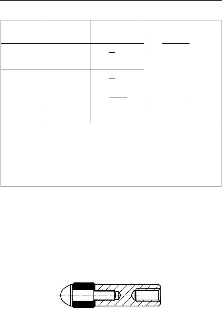
Figure 10.5 Carbide drawing dies for steel wires
Table 10.7 Dimensions of carbide drawing dies for steel wires (ISO-A) and wires made of nonferrous
metals (ISO-B)
Steel wire
d
1
in mm
Nonferrous
metals
d
1
in mm
d
2
in mm
h
2
in mm
d
3
in mm
h
3
in mm
l
3
in mm
2
E
in degrees
2
J
in de-
grees
1.0 1.5 8 4 28 12 0.5
2.0 2.5 10 8 28 16 0.5
3.0 3.5 12 10 28 20 0.6
90 90
5 6 16 13 43 25 0.9 60 75
6.5 8 20 17 43 32 1.2
9 10.5 25 20 75 35 1.5
12 13 30 24 75 40 1.8
60 60
Designation of a carbide drawing die for steel wires (A)
1
) with cylindrical casing (Z)
1
), nib
diameter d
2
= 14 mm, casing diameter d
3
= 28 mm, drawing hole diameter d
1
e.g. 1.8 mm,
approach angle 2
D
e.g. 16º (16), nib made of carbide from the application group G10, steel
(St) casing:
Drawing die AZ 14 í 28 í 1.8 í G 10 í St
102 10 Wire drawing
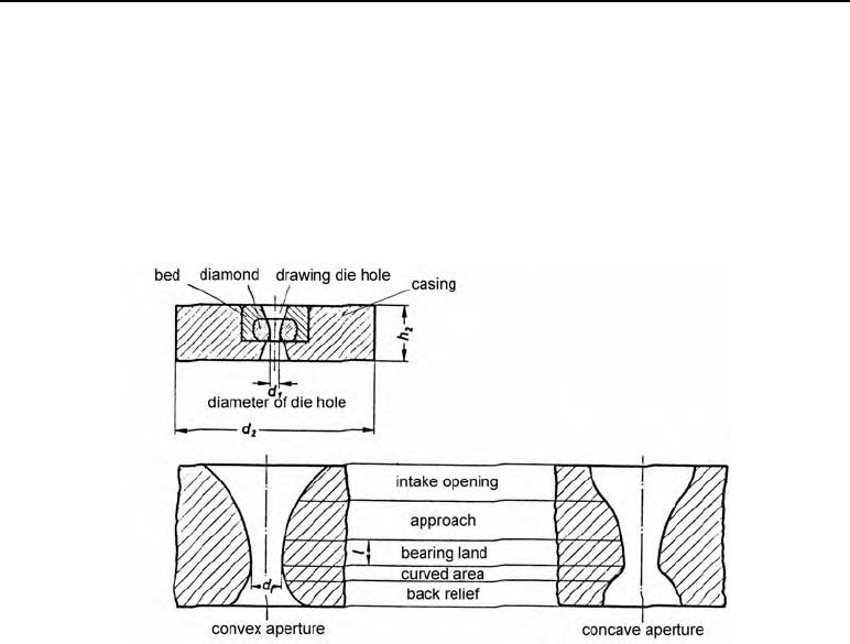
Diamond drawing dies
Diamond drawing dies are used for drawing fine and ultra-fine wires (0.01 mm to 1.5 mm)
made of copper, steel, tungsten and molybdenum.
The diamonds are sintered into a steel casing. This surrounds the diamond with a controlled
level of pre-stressing.
Figure 10.6 shows the principle of a diamond drawing die and a magnified view of the shape
of the drawing hole.
Figure 10.6 Elements of a diamond drawing die. a) Drawing hole details
The ratio of the length of the drawing ring to the drawing hole diameter l/d
1
is:
Steel wires of 0.01 í 1.0 mm diameter: 1 to 2.5
Brass and bronze of 0.2 í 1.0 mm diameter: 0.8 to 1.5
Aluminium of 0.2 í 1.0 mm diameter: 0.5 to 1.0
Designation of a diamond drawing die with a casing of 25 × 6 (25) made of brass Ms 58 for
the wet drawing of copper (B), drawing hole diameter d
1
= 0.18 mm (0.18), ratio of the bear-
ing land to the drawing hole diameter l/d
1
= 0.6 (0.6):
25 B 0.18 × 0.6.
Designation of a diamond drawing die with no casing for the hot drawing of tungsten wire (H),
drawing hole diameter d
1
= 0.02 mm (0.02), ratio of the bearing surface to the drawing hole
diameter l/d
1
= 1.5 (1.5):
H 0.02 × 1.5.
10.10 Example
The aim is to draw wire rod made of 42 Cr Mo 4, R
m
= 1200 N/mm
2
, from a diameter of d
0
=
12.5 mm to d
1
= 5.3 mm in a tandem drawing process. A machine with eight drawing stations
is available. Where:

10.10 Example 103
X
max
=
X
n
= 10 m/s
K
f
= 0.6 deformation efficiency
K
M
= 0.7 efficiency of the drawing machine.
Find:
1. Total deformation
2. Deformation per draw
3. Intermediate diameter at 2
nd
to 7
th
draws where deformation between draws is the same
4. Drawing force for the 1
st
draw
5. Driving power for the 1
st
draw.
Solution:
1.
tot.
2
0
p
3
1
12.5 ʌ /4
ln ln 1.72 172 %
5.3 ʌ /4
A
A
M
2.
tot
draw
p
p
172 %
21.5 % per draw
8Dr
M
M
3.
0
1
/ 2 0.215/ 2 0.175
12.5 12.5 12.5
11.2 mm
1.11349
d
d
ee e
M
1
2
/2
10.05 mm etc.
d
d
e
M
34 5678
9.02, 8.10, 7.27, 6.52, 5.85, 5.3dd dddd
4. Drawing force (1
st
draw)
m
1k p
dr
F
Ak
F
M
K
1
p
21.5 % 0.215
M
01m
22 2
str str str
420 880
420N/mm , 880N/mm , 650N/mm
2
kkk
2
2
1
2
1
ʌ
(11.2 mm)
98.52 mm
44
d
A
2
dr
2
98.52 mm 650 N 0.215
22 946 N 22.9 kN
0.6 mm
F
5. Driving power (1
st
draw)
5.1 Drawing speed (1
st
draw)
2
nn
1
2
1
10 m (5.3 mm) ʌ /4
(11.2 mm) ʌ /4
A
A
X
X
1
2.24 m/s .
X
5.2 Driving power (1
st
draw)
dr 1
1
M
22.9 kN 2.24 m
73.3 kW .
0.7 s
F
P
X
K

104 10 Wire drawing
10.11 Exercise on Chapter 10
1. What methods of wire drawing are there?
2. What kinds of machines for wire drawing are there?
3. How is the principal strain determined in wire drawing?
4. Why are the drawing speeds different at every drawing ring in tandem drawing?
5. What materials are drawing dies made of?
6. Which wires are carbide drawing dies used for?
11 Tube drawing
11.1 Definition
Tube drawing is the drawing of hollow parts, where the outside is formed by a drawing die
hole and the inside by a plug or a rod.
11.2 Tube drawing processes
Several manufacturing processes have been developed for drawing tubes. What the processes
all have in common is that the tube to be drawn is pointed at one end (pressed between two
semi-circular jaws). This pointed end is pushed through the drawing ring and then held tight by
the gripper attached to the carriage of the drawing machine. The drawing carriage then pulls
the tube through the stationary drawing ring. Table 11.1 shows tube drawing processes and the
features which characterise them.
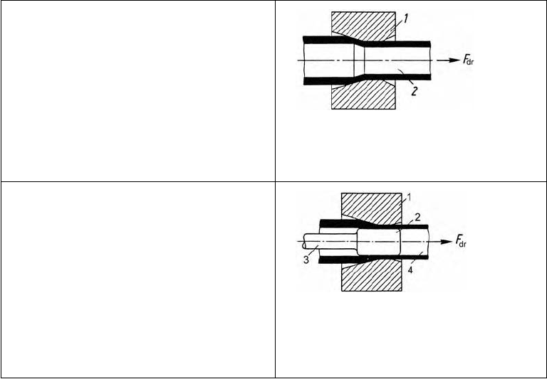
Table 11.1 Tube drawing processes
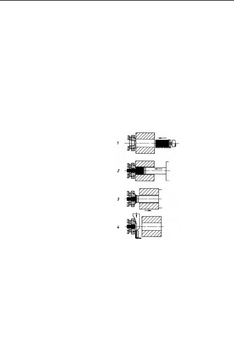
Drawing without a mandrel (tube sinking)
The tube is pulled through the drawing die hole
with no support from inside. In this process, only
the external diameter measurements are precise;
the wall thickness and internal diameter deviate
more. This process, known as tube sinking, is
only applied to tubes with smaller internal diame-
ters.
Figure 11.1 The principle of tube drawing with-
out a mandrel.
1 Drawing die, 2 workpiece
Drawing over a stationary mandrel (plug)
Here, the tube is pushed over a plug attached to
the mandrel. During the drawing process, the tube
is drawn through the annular gap formed between
the drawing ring and the plug.
As the annular gap is smaller than the wall thick-
ness of the tube to be drawn, the wall thickness is
reduced and the tube takes on the dimensions of
the drawing die hole for its external diameter, and
of the plug for its internal diameter.
Figure 11.2 The principle of drawing over a sta-
tionary mandrel.
1 Drawing ring, 2 workpiece, 3 man-
drel, 4 plug
106 11 Tube drawing
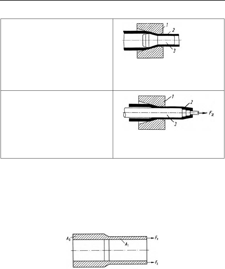
Table 11.1 Tube drawing process (continued)
Drawing over a floating plug
The set-up is the same as with plug drawing.
Here, however, the plug is not attached to a man-
drel, but is pushed in before drawing takes place.
Because of its conical shape, during the drawing
process it is automatically drawn in the direction
of drawing, through the die.
Figure 11.3 The principle of drawing over a
floating plug.
1 Drawing ring, 2 workpiece, 3 floa-
ting plug
Drawing over a moving mandrel
Instead of a plug, here, a long rod (mandrel), re-
duced at the foremost end and with a cylindrical
shoulder, is pushed into the tube. The cylindrical
tip is pushed through the pointed end of the tube.
The drawing grip takes hold of this cylindrical
peg.
During the drawing operation, the rod and the
tube are then simultaneously moved in the draw-
ing direction.
Figure 11.4 The principle of drawing over a
moving mandrel. 1 Drawing ring,
2 workpiece, 3 moving mandrel
11.3 Principal strain and drawing force
The limits for the permissible principal strains come from the required drawing force.
As the drawing force must be carried by the tube cross-section A
x
(Figure 11.5) after deforma-
tion, it must remain lower than the tensile force.
F
dr
F
perm
Figure 11.5 Tube cross-sections A
0
before and A
1
after the draw
This provides the permissible deformations. If the required cross-sectional reduction can not be
achieved at one drawing, as F
dr
! F
perm
, then intermediate annealing must be carried out after
the first draw.
Table 11.2 shows how the drawing force F
dr
and the tensile force F
perm
can be calculated
mathematically.
11.4 Drawing tooling 107
Table 11.2 Calculating principal strain and drawing force
Drawing force in N
Type of drawing
Permissible deforma-
tion
M
p
perm
in %
(from drawing force)
Principal strain
M
p
(–)
Tube sinking
20 – 50
M
p
= ln
0
1
d
d
M
p
%
=
M
p
· 100 (%)
Plug drawing
30 – 50
m
1str p
dr
F
Ak
F
M
K
for 2
D
= 16° (optimum opening
angle):
K
F
= 0.4 – 0.6 for
M
p
= 15 %
K
F
= 0.7 – 0.8 for
M
p
= 50 %
p
erm 1 m
FAR
Rod drawing
40 – 60
M
p
= ln
0
1
A
A
M
p
= ln
22
00
22
11
Dd
Dd
M
p(
%)
=
M
p
· 100 (%)
F
dr
must be lower than F
perm
, how-
ever, or the tube breaks off.
M
p
– principal strain
D
0
in mm external diameter before drawing
d
0
in mm internal diameter before drawing
A
0
in mm
2
tube cross-section before drawing
D
1
in mm external diameter after drawing
d
1
in mm internal diameter after drawing
A
1
in mm
2
tube diameter after drawing
k
str
m
in N/mm
2
R
m
in N/mm
2
F
dr
in N
F
perm
in N
K
F
mean flow stress
tensile strength of the tube mate-
rial
drawing force
maximum force which can be
carried into the tube cross-
section
deformation resistance
11.4 Drawing tooling
Drawing tooling made of carbide is mainly used for tube drawing.
The drawing die is similar in construction to those shown in Figure 10.5 for wire drawing.
The drawing mandrel consists of the steel body (Figure 11.6) and the actual mandrel made of
carbide.
Once more, G10 to G60 are common carbide types used.
Figure 11.6 Drawing mandrel with screwed-on carbide ring

108 11 Tube drawing
11.5 Example
The aim is to draw a tube made of Ck 45 (R
m
= 800 N/mm
2
) with initial dimensions of D
0
=
45, d
0
= 30, bringing it to D
1
= 40 und d
1
= 28.
Find:
1. Drawing force
2. Permissible limiting force
3. Can the cross-sectional reduction be achieved in one drawing?
Solution:
22
22
00
p
22 2 2
11
45 30
ln ln 0.32 32%
40 28
Dd
Dd
M
o
m
0
2
str str
1 str
390, 840, 615 N/mmkkk
m
22 2
1str p
dr
2
F
(40 28 ) mm 615 N 0.32
4 0.7 mm
Ak
F
M
K
S
F
dr
= 180 178 N #180 kN
2
1m
perm
332
640.9 mm 800 N
512.7 kN
10 N/kN 10 N/kN mm
AR
F
As F
dr
is considerably smaller than F
perm
, this deformation can take place in one drawing.
11.6 Exercise on Chapter 11
1. What kinds of tube drawing processes are there?
2. How do they differ from one another?
12 Extrusion
12.1 Definition
Extrusion (Figure 12.1) is a bulk forming process where a heated billet, confined in a con-
tainer, is pressed through a shaping die by a punch. In this process, the emerging product takes
on the shape of the die.
Extrusion is a forming process involving pressure. The actual deformation from a billet into an
extrusion takes place in the funnel-shaped deformation zone in front of the die.
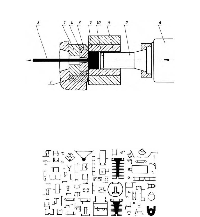
Figure 12.1 The principle of direct extrusion of a solid shape. 1 pressure plate, 2 punch, 3 die (tool)
holder, 4 die, 5 container, 6 plunger, 7 slider, 8 extrusion, 9 billet, 10 dummy block
12.2 Application
The process is used to produce solid and hollow profiles of all kinds (Figure 12.2) from alu-
minium and copper alloys and from steel.
Figure 12.2 Typical extrusion profiles
110 12 Extrusion
12.3 Starting stock
Solid or hollow billets heated to hot forming temperature.
To manufacture hollow profiles, hollow billets are required.
In tube production, the hollow billet can also be produced in the extrusion press by a piercing
operation which precedes the actual extrusion.
12.4 The extrusion process
Extrusion processes are divided up:
a) depending on the way the billet is pushed into the container, into:
direct and indirect extrusion.
b) depending on the product produced during extrusion, into:
solid and hollow extrusion.
12.4.1 Direct extrusion (forward
extrusion)
Here, the material flow of the extruded
p
roduct and the punch movement (Figure
12.1) are in the same direction.
The billet (Figure 12.3), heated to form-
ing temperature, is put into the machine.
The punch, separated from the material
b
y the dummy block, presses the billet
through the die.
The residual material is laid clear by
moving the container back, then sheared
or sawn off.
Figure 12.3
Sequence of operations during direct extrusion. 1 put
billet and dummy block in the press, 2 extrude billet,
3 move the container back, 4 cut off residual material
12.4.2 Indirect extrusion (backward extrusion)
In backward extrusion (Figure 12.4) the die is located on top of the extrusion punch, which is
hollowed out.
The flow of the material is in the opposite direction to the relative motion of the punch. Here,
the plunger and the container carry out the extrusion movement simultaneously.
This means that in backward extrusion there is no relative motion between the billet and the
container. This relative motion (in forward extrusion) is a disadvantage as it produces further
heat by friction, which can only be kept within limits by reducing the speed of the press.