Trent E.M., Wright P.K. Metal Cutting
Подождите немного. Документ загружается.

THE BUILT-UP EDGE 43
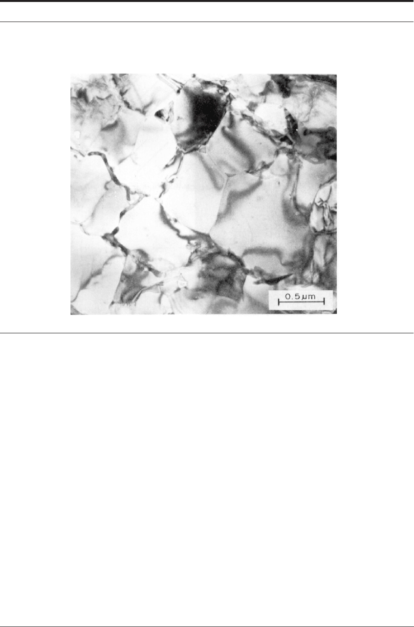
FIGURE 3.20 Transmission electron micrograph (TEM) of the structure of the flow zone in 0.19%C steel
machined at 70 m min
-1
(225 ft/min) (Courtesy of A. Shelbourn)
The built-up edge is not a separate body of metal during the cutting operation. Diagrammati-
cally it should be depicted as in Figure 3.22. The new work surface is being formed at O
´ and
the under surface of the chip at B, but between O
´ and B the built-up edge and the work material
are one continuous body of metal, not separated by free surfaces.
The zone of intense and rapid shear strain has been transferred from the tool surface to the top
of the built-up edge. This illustrates the principle that, under seizure conditions, relative move-
ment does not necessarily take place immediately adjacent to the interface.
The built-up edge is a dynamic structure, being constructed of successive layers greatly hard-
ened under extreme strain conditions. When cutting steel, for example, many workers have
shown the hardness of a built-up edge to be as high as 600 or 650HV, determined by micro-hard-
ness tests. Wallbank
11
studied the structures of the built-up edges formed when cutting steel,
using TEM.
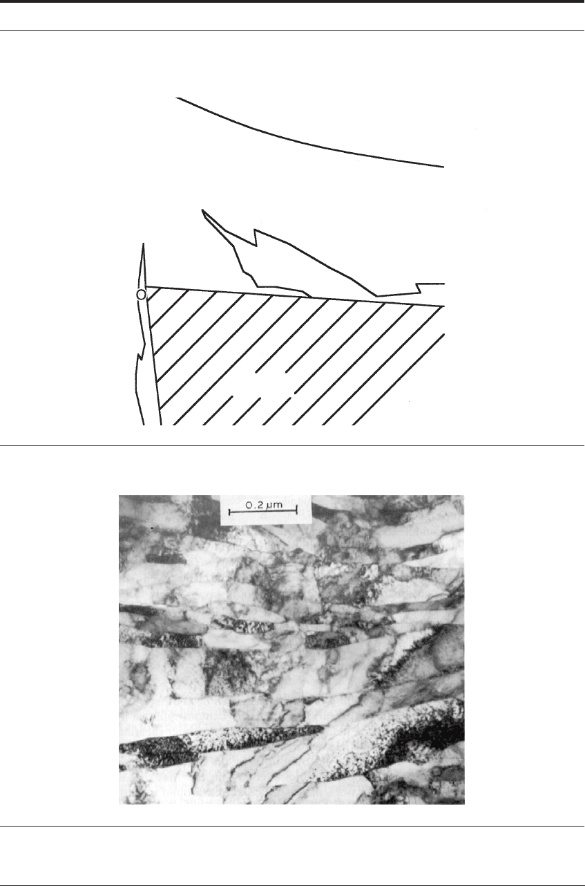
Figure 3.23 is a typical micrograph showing the very fine elongated ferrite cell structure. The
cementite was so finely dispersed as to be very difficult to resolve and identify at the highest
magnification. The material of the built-up edge had thus been very severely strain hardened, but
the temperature had not increased to the stage where recrystallization could take place. The
built-up edge structures contrast strongly with the equi-axed structures of the flow-zone (Figure
3.20). The strain-hardened work material of the built-up edge can support the stress imposed by
the cutting operation and it functions as an extension to the cutting tool.
44 THE ESSENTIAL FEATURES OF METAL CUTTING
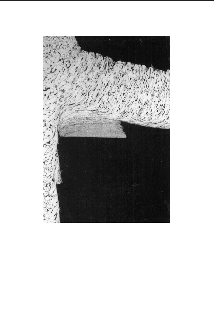
FIGURE 3.21 Section through quick-stop showing built-up edge after cutting 0.15% C steel at low speed
in air
The new work surface initiates at O´ (Figure 3.22) and the under surfaces of the chip at B are
formed by fracture through the work-hardened material. Some severely strained material
remains on the two newly formed surfaces. At the top of the built-up edge (between O
´ and B in
Figure 3.22) intense strain-hardening is accompanied by piling up of dislocations at inclusions
and other structural discontinuities. In the center of this region, formation of micro-cracks is
inhibited by high compressive stress, but as the strain-hardened material flows towards O
´ or B,
compressive stress is reduced and micro-cracks develop and join together to initiate fracture.
The new surfaces follow the general direction of the flow-lines in the deforming structure, often
along elongated plastic inclusions, but frequently moving from one line of micro-cracks to
another to produce a typically rough surface.
15
THE BUILT-UP EDGE 45
FIGURE 3.22 Form of built-up edge
7
FIGURE 3.23 TEM from built-up edge of 0.1% C steel (After Wallbank
11
)
Tool
′
B
46 THE ESSENTIAL FEATURES OF METAL CUTTING
This mode of fracture leads to an increase in size and change of shape of the built-up edge.
This continues until the growing built-up edge becomes unstable in the stress field when frag-
ments are broken away by a different fracture mechanism. Fracture across, rather than along, the
flow direction is initiated, probably as a thermoplastic instability, in a very thin shear zone form-
ing a much smoother fracture surface. Such a fracture can be seen on the cut surface in Figure
3.21. (The important role of thermoplastic shear bands in metal cutting is further treated in
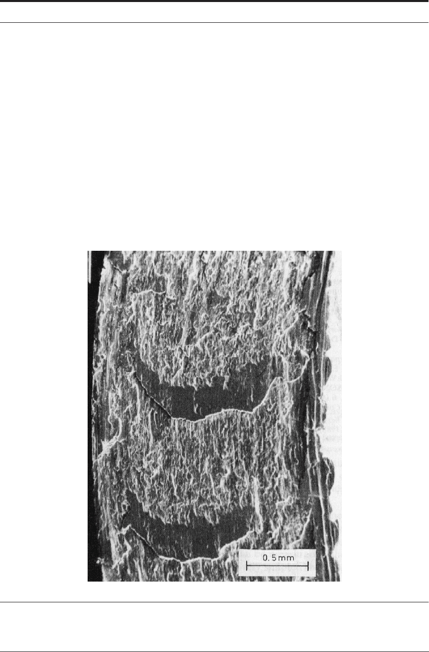
Chapter 5.) This leads to a typical feature of machined surfaces and the under surface of chips
when a built-up edge is present. There are smooth, shiny patches on a rough surface as shown on
the under side of a chip in Figure 3.24.
16
There is no hard and fast line between a built-up edge (Figure 3.21) and a flow-zone (Figure
3.18). Seizure between tool and work material is a feature of both situations and every shade of
transitional form between the two can be observed. The built-up edge occurs in many shapes and
sizes and it is not always possible to be certain whether or not it is present. In the transitional
region, when the built-up edge becomes very thin, some writers refer to it as a built-up layer.
FIGURE 3.24 Scanning electron micrograph of under surface of steel chip, after cutting with a built-up
edge. Rough and smooth areas result from fracture along and across lines of flow, respectively (Courtesy
of S. Barnes
16
)

MACHINED SURFACES 47
3.9 MACHINED SURFACES
In conventional language, surfaces formed by cutting are spoken of as different in character
from those formed by fracture. Figures 3.18 and 3.21 demonstrate that in metal cutting the
machined surfaces are, in fact, formed by fracture under shearing stress. The new surface rarely
originates precisely at the cutting edge of the tool. Figure 3.21 shows that, in the presence of a
built-up edge, the fracture forming the new surface may have its origin above the tool edge.
Wallbank
11
has shown that, when a flow-zone is present, the work material wraps itself around a
sharp cutting edge and the new surface is formed where the work material breaks contact with
the tool flank, a short distance below the edge. With ductile metals and alloys, both sides of a
shear fracture are plastically strained, so that some degree of plastic strain is a guaranteed fea-
ture of machined surfaces. The amount of strain and the depth below the machined surface to
which it extends, can vary greatly, depending on the material being cut, the tool geometry, and
the cutting conditions, including the presence or absence of a lubricant.
12
The deformed layer on the machined surface can be thought of as that part of the flow-pattern
around the cutting edge which passes off with the work material, so that an understanding of the
flow-pattern, and the factors which control it, is important in relation to the character of the
machined surface. The presence or absence of seizure on those parts of the tool surface where
the new work surface is generated can have a most important influence, as can the presence or
absence of a built-up edge and the use of sharp or worn tools. These factors influence not only
the plastic deformation, hardness and properties of the machined surface, but also its roughness,
its precise configuration and its appearance.
3.10 SUMMARY AND CONCLUSION
The main objective of machining is the shaping of the new work surface. It may seem, there-
fore, that too much attention is paid in this book to the formation of the chip, which is a waste
product. But the consumption of energy occurs mainly in the formation and movement of the
chip, and for this reason, the main economic and practical problems concerned with rate of metal
removal and tool performance can be understood only by studying the behavior of the work
material as it is formed into the chip and moves over the tool.
Detailed knowledge of the chip formation process is also required for the understanding of the
accuracy and condition of the machined surface of the desired component. Machined surfaces
are inevitably damaged to some degree, since the chip is formed by the shear fracture at high
strain (as described in the previous section).
During the “normal machining” of routine consumer products (shown at the top-right of Fig-
ure 1.1.), the sub-surface damage may not be of great concern. Probably, the in-service perfor-
mance of such consumer products will not suffer much from some minor amounts of sub-surface
strain of the kind that can be seen in the quick-stop sections.
However, in the machining of more critical items - certain aircraft components for example -
the sub-surface strain damage might negatively impact on fatigue life. In this regard, it is advis-
able to approach the final part dimensions with a sequence of carefully planned roughing and

48 THE ESSENTIAL FEATURES OF METAL CUTTING
finishing cuts. It is important to consider that the finishing cuts might “inherit” damage (Figure
3.25) from the previous roughing cuts.
17-18
To arrive at an acceptable accuracy/tolerance with minimal damage, it may, in certain circum-
stances, be advisable to use a modest roughing cut followed by two lighter finishing cuts, rather
than one more aggressive roughing cut which causes such sub-surface damage to the extent that
only one finishing cut cannot correct the surface. A small sacrifice in overall machining time
may, in such a case, be a better strategy for minimizing sub-surface damage. Further research is
desirable to investigate such strategies for different commercial alloys.
The issues related to sub-surface damage become even more critical in the “precision” and
“ultra-precision” ranges in Figure 1.1. In such operations, the value of the undeformed chip
thickness (t
1
) during finishing cuts is very small. It is useful to refer to Figures 2.1 and 3.1 and
relate the value of t
1
, the feed rate, to any possible tool wear, blemishes, nicks, or general round-
ing of the tool’s edge during use (at position O in Figure 3.1). During roughing cuts, with a large
value of t
1
, such blemishes or rounding will not be a major influence on the general smoothness
of the chip flow process. By contrast, thinking about relative proportions, when t
1
is very small,
as in precision finishing, any blemishes or tool-edge rounding by wear will have a more dra-
matic interference on the general smoothness of chip flow and consequently on the quality of the
surface finish of the part being machined.
Thus, when considering the condition of the machined surface, especially for precision
machining, the sharpness and integrity of the cutting edge is probably the most important issue
to focus on.
During a particular cut as the edge wears and becomes slightly blunt or rounded, the strain
imposed on the machined surface increases. Intuitively, it can be imagined that a rounded tool
edge is, at high magnification, like a blunt wedge being dragged across the surface. The more
blunt and rounded the edge becomes, the more the action resembles a blunt hardness-tester being
dragged on the surface causing the familiar strain fields seen in standard plasticity textbooks.
19
As the tool wears even more, the effect can cause shear lamellae to spall-off, visibly creating
rough “ears” on the machined surface and on the underside of the chip.
Figures 3.26 to 3.30 have been drawn to summarize the development of such effects over time.
Experience has shown that by the time the tool exhibits 0.75mm (0.03 inches) of flank wear, the
tool is essentially worn-out because its blunted state causes considerable damage on the
machined surface.
Also, at the end of the tool’s life the “indenting rather than cutting” effect of its worn edges
and clearance face can push-up a “collar formation”. This occurs at the outer shoulder of the bar
in Figure 2.1 and is shown schematically for face-milling in Figure 3.29.
Clearly this effect is unacceptable for high accuracy machining and the tool should be changed
well before the usual 0.75mm (0.03 inches) flank wear limit. However, even at lesser amounts of
flank wear, some damage occurs, building up on a gradual basis. Figures 3.26 to 3.28 have been
drawn to show the gradual transition that occurs. A highly skilled machinist can track these
events, and also correlate them with aural and visual cues as summarized in Figure 3.30.
In conclusion, the characteristics of machined surfaces, especially those of high-quality form-
ing dies and components that demand high-precision, are greatly dependent on the flow patterns,
stresses and temperatures at this all-important tool edge, O, and these are the subjects of the next
chapters.
SUMMARY AND CONCLUSION 49
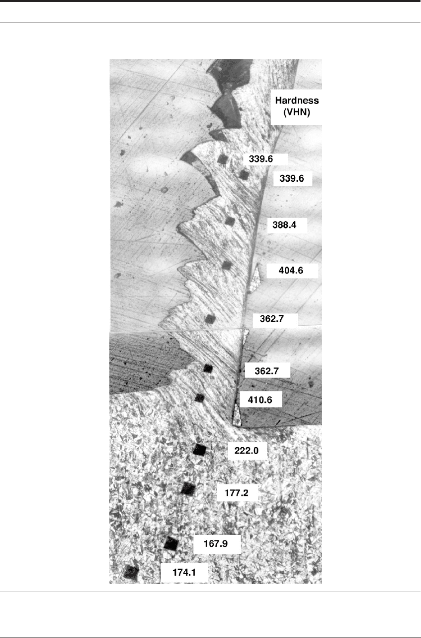
FIGURE 3.25 Microhardness results show damage by work hardening of tool surface. Machining
austenitic stainless steel at 100 m min
-1
50 THE ESSENTIAL FEATURES OF METAL CUTTING
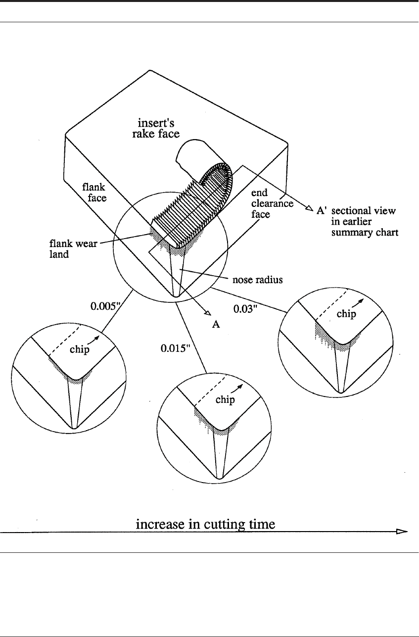
FIGURE 3.26 Expanded detail of insert from Figure 2.1 showing the development of flank wear from
0.005 inches (~0.15mm) to 0.03 inches (~0.75mm).

SUMMARY AND CONCLUSION 51
FIGURE 3.27 Corresponding changes in surface finish of the part as tool wear progresses
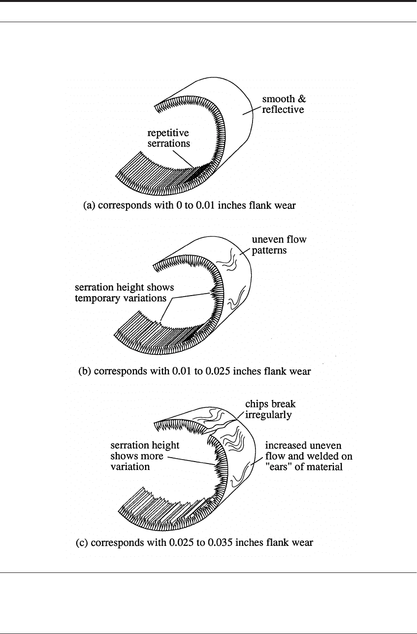
52 THE ESSENTIAL FEATURES OF METAL CUTTING
FIGURE 3.28 Corresponding changes in the undersurface of the chip as tool wear progresses