Trent E.M., Wright P.K. Metal Cutting
Подождите немного. Документ загружается.

THE CHIP 23
3.2 THE CHIP
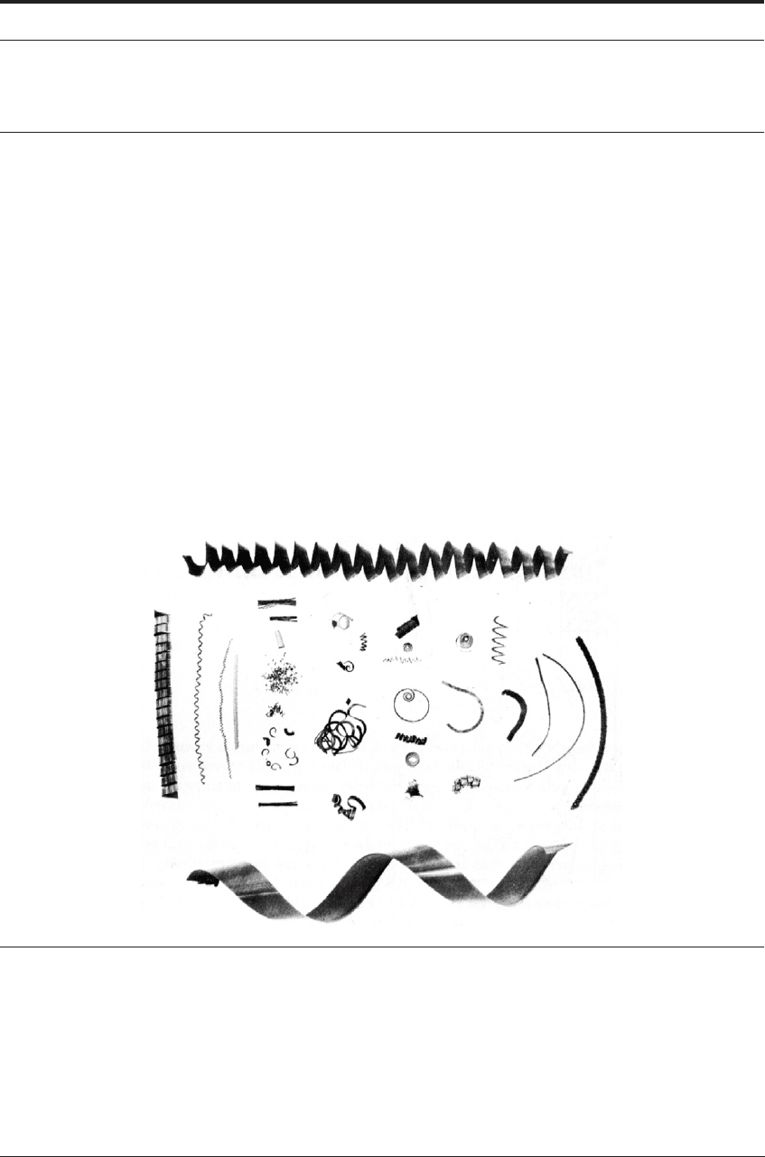
The chip is enormously variable in shape and size in industrial machining operations; Figure
3.2 shows some of the forms. The formation of all types of chips involves a shearing of the work
material in the region of a plane extending from the tool edge to the position where the upper
surface of the chip leaves the work surface (OD in Figure 3.1). A very large amount of strain
takes place in this region in a very short interval of time, and not all metals and alloys can with-
stand this strain without fracture. Gray cast iron chips, for example, are always fragmented, and
the chips of more ductile materials may be produced as segments, particularly at very low cut-
ting speed. This discontinuous chip is one of the principal classes of chip form, and has the prac-
tical advantage that it is easily cleared from the cutting area. Under a majority of cutting
conditions, however, ductile metals and alloys do not fracture on the shear plane and a continu-
ous chip is produced (Figure 3.3). Continuous chips may adopt many shapes - straight, tangled
or with different types of helix. Often they have considerable strength, and control of chip shape
is one of the problems confronting machinists and tool designers. Continuous and discontinuous
chips are not two sharply defined categories; every shade of gradation between the two types can
be observed.
FIGURE 3.2 Chip shapes
The longitudinal shape of continuous chips can be modified by mechanical means, for exam-
ple by grooves in the tool rake face, which curl the chip into a helix. The cross section of the
chips and their thickness are of great importance in the analysis of metal cutting, and are consid-
ered later in some detail. For the purpose of studying chip formation in relation to the basic prin-
ciples of metal cutting, it is useful to start with the simplest possible cutting conditions,
consistent with maintaining the essential features common to these operations.
24 THE ESSENTIAL FEATURES OF METAL CUTTING
3.3 TECHNIQUES FOR STUDY OF CHIP FORMATION
Before discussing chip shape, the experimental methods used for gathering the information are
described. The simplified conditions used in the first stages of laboratory investigations are
known as orthogonal cutting. In orthogonal cutting the tool edge is straight, it is normal to the
direction of cutting, and normal also to the feed direction. On a lathe, these conditions are
secured by using a tool with the cutting edge horizontal, on the center line, and at right angles to
the axis of rotation of the workpiece. If the workpiece is in the form of a tube whose wall thick-
ness is the depth of cut, only the straight edge of the tool is used. In this method the cutting speed
is not quite constant along the cutting edge, being highest at the outside of the tube, but if the
tube diameter is reasonably large this is of minor importance. In many cases the work material is
not available in tube form, and what is sometimes called semi-orthogonal cutting conditions are
used, in which the tool cuts a solid bar with a constant depth of cut. In this case, conditions at the
nose of the tool are different from those at the outer surface of the bar. If a sharp-nosed tool is
used this may result in premature failure, so that it is more usual to have a small nose radius. To
avoid too great a departure from orthogonal conditions, the major part of the edge engaged in
cutting should be straight. Strictly orthogonal cutting can be carried out on a planing or shaping
machine, in which the work material is in the form of a plate, the edge of which is machined.
The cutting action on a shaper is, however, intermittent, the time of continuous machining is
very short, and speeds are limited. For most test purposes the lathe method is more convenient.
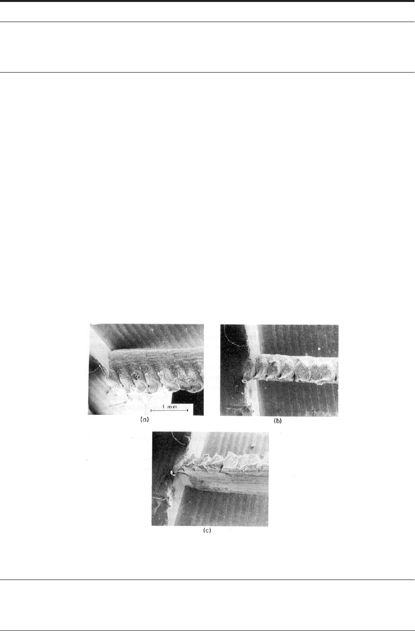
FIGURE 3.3 SEM photographs from three directions of a forming chip of steel cut at 48 m min
-1
(150 ft/
min) and 0.25 mm (0.01 in) per rev feed; image (a) from above, image (b) is a side view that can be
compared with Figure 3.1 and image (c) from below the cutting zone (Courtesy of B.W. Dines)

CHIP SHAPE 25
The study of the formation of chips is difficult, because of the high speed at which it takes
place under industrial machining conditions, and the small scale of the phenomena which are to
be observed. High speed cine-photography at relatively low magnification has been used. Early
employment of this method was confined to study of changes in external shape during chip for-
mation. These observations may mislead if interpreted as demonstrating the cutting action at the
center of the chip. This limitation has been partly overcome by a method demonstrated by Tön-
shoff and his colleagues.
1
A polished and etched work material surface is held against a transpar-
ent silica plate and machined in such a way that the role of different phases in the work material
(e.g. graphite flakes in cast iron) can be observed during the cutting process. With this method,
the constraint of the silica plate provides conditions more like those at the center of the chip.
There are still limitations on the magnification at which observations can be made and on the
range of cutting speeds. Tabor and colleagues
2,3
have studied the movement of the chip across
the rake face of transparent sapphire tools during cutting by observing the interface through the
tool. High speed cine-photography was again used. This method is confined to the use of trans-
parent tool materials and it cannot be assumed that the action at the interface is the same as when
machining with metallic tools.
3
No useful information about chip formation can be gained by studying the end of the cutting
path after cutting has been stopped in the normal way by disengaging the feed and the drive to
the work. By stopping the cutting action suddenly, however, it is possible to retain many of the
important details - to “freeze” the action of cutting. Several “quick-stop” mechanisms have been
devised for this purpose. One of the most successful involves the use of a humane killer gun to
propel a lathe tool away from the cutting position at very high speed in the direction in which the
work material is moving.
4
Sometimes the chip adheres to the tool and separates from the bar, but
more usually the tool comes away more or less cleanly, leaving the chip attached to the bar. A
segment of the bar, with chip attached, can be cut out with a hacksaw and examined in detail at
any required magnification. For external examination and photography, the scanning electron
microscope (SEM) is particularly valuable because of its great depth of focus. Figure 3.3 shows
an example of chip formation recorded in this way.
Much of the information in this book has been obtained by preparing metallographic sections
through “quick-stop” specimens to reveal the internal action of cutting. Because any one speci-
men illustrates the cutting action at one instant of time, several specimens must be prepared to
distinguish those features which have general significance from others which are peculiar to the
instant at which cutting stopped.
3.4 CHIP SHAPE
Even with orthogonal cutting, the cross section of the chip is not strictly rectangular. Since it is
constrained only by the rake face of the tool, the metal is free to move in all other directions as it
is formed into the chip. The chip tends to spread sideways, so that the maximum width is some-
what greater than the original depth of cut. In cutting a tube it can spread in both directions, but
in turning a bar it can spread only outward. The chip spread is small with harder alloys, but when
cutting soft metals with a small rake angle tool, a chip width more than one and one half times

26 THE ESSENTIAL FEATURES OF METAL CUTTING
the depth of cut has been observed. Usually the chip thickness is greatest near the middle, taper-
ing off somewhat towards the sides.
The upper surface of the chip is always rough, usually with minute corrugations or steps, Fig-
ure 3.3a. Even with a strong, continuous chip, periodic cracks are often observed, breaking up
the outer edge into a series of segments. A complete description of chip form would be very
complex, but, for the purposes of analysis of stress and strain in cutting, many details must be
ignored and a much simplified model must be assumed, even to deal with such an uncomplicated
operation as lathe turning. The making of these simplifications is justified in order to build up a
valuable framework of theory, provided it is born in mind that real-life behavior can be com-
pletely accounted for only if the complexities, which were ignored first, are reintroduced.
An important simplification is to ignore both the irregular cross section of real chips and the
chip spread, and to assume a rectangular cross section, whose width is the original depth of cut,
and whose height is the measured mean thickness of the chip. With these assumptions, the for-
mation of chips is considered in terms of the simplified diagram, Figure 3.1, an idealized section
normal to the cutting edge of a tool used in orthogonal cutting.
3.5 CHIP FORMATION
In practical tests, the mean chip thickness can be obtained by measuring the length, l, and
weight, W, of a piece of chip. The mean thickness, t
2
, is then
(3.1)
where ρ = density of work material (assumed unchanged during chip formation) and w = width
of chip (depth of cut).
The mean chip thickness is a most important parameter. In practice the chip is never thinner
than the feed, which in orthogonal cutting, is equal to the undeformed chip thickness, t
1
(Figure
3.1). In most textbooks and papers, it is usual to formally define a term (r), called “the chip
thickness ratio”. The value of r is the ratio of the undeformed chip thickness to the deformed
chip thickness, namely, r = t
1
/t
2
, with r<<1.
Chip thickness is not constrained by the tooling, and, with many ductile metals, the chip may
be five times as thick as the feed, or even more. Thus, it is important to re-emphasize that r will
always be less than unity and often in the range 0.2 to 0.5. The chip thickness is related to the
tool rake angle, α, and the shear plane angle φ (Figure 3.1).
The latter is the angle formed between the direction of movement of the workpiece OA (Figure
3.1) and the shear plane represented by the line OD, from the tool edge to the position where the
chip leaves the work surface.
For purposes of simple analysis the chip is assumed to form by shear along the shear plane. In
fact the shearing action takes place in a zone close to this plane.
It is assumed that the work material is incompressible and no side spread occurs. From the
geometry of the cut (see Figure 3.1), it can be shown that,
t
2
W
ρwl
---------=
CHIP FORMATION 27
or
Hence
(3.2)
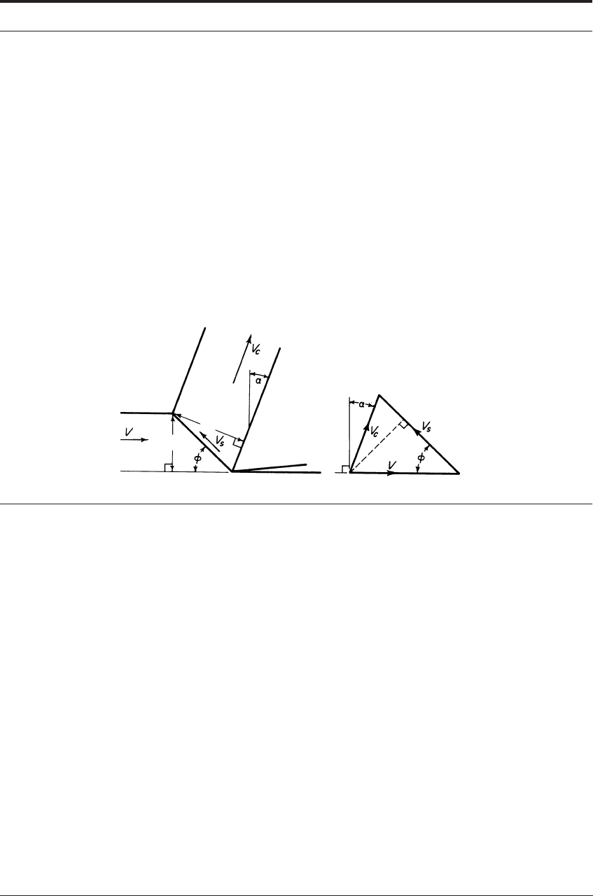
FIGURE 3.4 The relationship between shear angle, chip thickness and velocities. This orientation is the
same as Figures 2.1 and 3.1 but rotated ninety degrees clockwise to show orthogonal planing/shaping.
If the chip thickness ratio is low, the shear plane angle is small and the chip moves away
slowly (e.g. for copper), while a large shear plane angle means a thin, high-velocity chip (e.g. for
aluminum alloys). As any volume of metal, e.g. klmn (Figure 3.1) passes through the shear zone,
it is plastically deformed to a new shape - pqrs. The amount of plastic deformation (shear strain,
γ) is related to the shear plane angle φ and the rake angle α by the following equations
5
From the velocity-vector diagram above,
and
To derive an expression for the shear strain, the deformation can be idealized as a process of
block slip or preferred slip planes, as shown in Figure 3.5. The shear strain
OD
t
1
φsin
-----------
t
2
φα–()cos
--------------------------==
t
1
φsin
-----------
t
2
φα φαsinsin+coscos
------------------------------------------------------=
φtan
r αcos
1 r αsin–
-----------------------=
t
2
t
1
O
D
V
c
φsin
φα–()cos
--------------------------
V=
V
s
αcos
φα–()cos
--------------------------
V=

28 THE ESSENTIAL FEATURES OF METAL CUTTING
i.e.,
or
(3.3)
FIGURE 3.5 The shear-strain model. (after Piispanen
5
)
The strain may also be expressed in terms of the shearing velocity
The strain rate in cutting is given by
(3.4)
where is the thickness of the deformation zone, and is the time to achieve the final value
of strain.
The meaning of ‘shear strain’, and of the units in which it is measured, is shown in the inset
diagram in Figure 3.6. A unit displacement of one face of a unit cube is a shear strain of (γ = 1).
γ
ΔS
Δy
-------
OA
CD
--------
OD
CD
---------
D
A
CD
--------+== =
γφα–()φcot+tan=
γ
αcos
φφα–()cossin
--------------------------------------=
Ο
Ο
γ
V
s
V φsin
---------------=
γ
·
ΔS
ΔyΔt
------------
V
s
Δy
------
αcos
φα–()cos
--------------------------
V
Δy
------
⋅===
Δy Δt

THE CHIP/TOOL INTERFACE 29
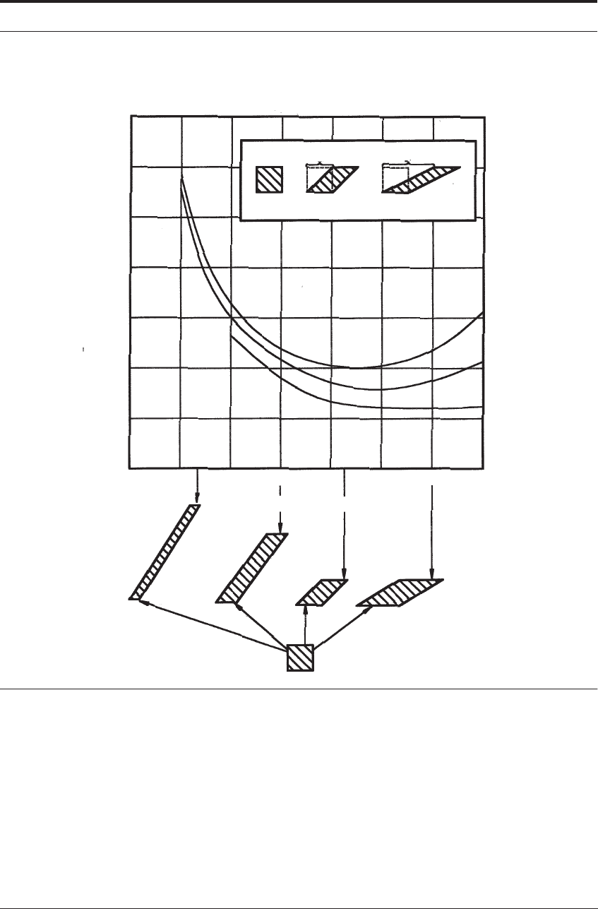
Figure 3.6 is a graph showing the relationship between the shear strain in cutting and the shear
plane angle for three values of the rake angle.
For any rake angle there is a minimum strain when the mean chip thickness is equal to the feed
(t
2
= t
1
). For zero rake angle, this occurs at φ = 45
o
. The change of shape of a unit cube after
passing through the shear plane for different values of the shear plane angle is shown in the
lower diagram of Figure 3.6 for a tool with a zero rake angle. The minimum strain at φ = 45
o
is
apparent from the shape change.
At zero rake angle the minimum shear strain is 2. The minimum strain becomes less as the
rake angle is increased, and if the rake angle could be made very large, the strain in chip forma-
tion could become very small.
In practice the optimum rake angle is determined by experience; too large an angle weakens
the tool and leads to fracture. Rake angles higher than 30
o
are seldom used and, in recent years,
the tendency has been to decrease the rake angle to make the tools more robust, to enable harder
but less tough tool materials to be used (Chapters 7 and 8).
Thus, even under the best cutting conditions, chip formation involves very severe plastic
deformation, resulting in considerable work-hardening and structural change. It is not surprising
that metals and alloys lacking in ductility are periodically fractured on the shear plane.
3.6 THE CHIP/TOOL INTERFACE
The formation of the chip by shearing action at the shear plane is the aspect of metal cutting
which has attracted most attention from those who have attempted analyses of machining. Of at
least equal importance for the understanding of machinability and the performance of cutting
tools is the movement of the chip and of the work material across the faces and around the edge
of the tool.
In most analyses this has been treated as a classical friction situation, in which ‘frictional
forces’ tend to restrain movement across the tool surface, and the forces have been considered in
terms of a coefficient of friction (μ) between the tool and work materials. However, detailed
studies of the tool/work interface have shown that this approach is inappropriate to most metal
cutting conditions. It is necessary, at this stage, to explain why classical friction concepts do not
apply and to suggest a more suitable model for analyzing this situation.
The concept of coefficient of friction derives from the work of Amontons and Coulomb who
demonstrated that, in many common examples of the sliding of one solid surface over another,
the force (F) required to initiate or continue sliding is proportional to the force (N) normal to the
interface at which sliding is taking place
(3.5)
This coefficient of friction μ is dependent only on these forces and is independent of the slid-
ing area of the two surfaces. The work of Bowden and Tabor,
6
Archard, and many others has
demonstrated that this proportionality results from the fact that real solid surfaces are never com-
pletely flat on a molecular scale, and therefore make contact only at the tops of the hills, while
the valleys are separated by a gap.
F μN=
30 THE ESSENTIAL FEATURES OF METAL CUTTING
FIGURE 3.6 Strain on shear plane (γ) vs shear plane angle (φ) for three values of rake angle (α)
Under loading conditions used in engineering sliding mechanisms, the real contact area is very
small, often less than one hundredth of the apparent area of the sliding surfaces. The mean stress
acting on the real contact area supporting the load is equal to the yield stress of the material. If
the compressive force normal to the interface is doubled, the real contacts supporting the load
are plastically deformed until they double in area, so that the mean stress on them remains con-
stant. In the areas of real contact, the atoms of the two surfaces are brought within range of their
very strong attractive forces, i.e. they are atomically bonded. The frictional force is that force
required to shear these areas of real contact. This friction force is proportional to the real contact
area and therefore also proportional to the normal force. In engineering sliding mechanisms, the
Shear plane angle ∅
6
5
4
3
2
1
0 10203040506070
Shear Strain
α=0°
α=10°
α=25°
γ=1 γ=2

THE CHIP/TOOL INTERFACE 31
coefficient of friction, F/N, is therefore a useful concept - i.e. under conditions where the normal
stress on the apparent contact area is very small compared with the yield stress of the materials.
When the normal force is increased to such an extent that the real area of contact is a large pro-
portion of the apparent contact area, it is no longer possible for the real contact area to increase
proportionately to the load. In the extreme case, where the two surfaces are completely in con-
tact, the real area of contact becomes independent of the normal force, and the frictional force
becomes that required to shear the material across the whole interface. When two materials of
different strengths are in contact, as in metal cutting, the force required to move one body over
the other becomes that required to shear the weaker of the two materials across the whole area.
This force is almost independent of the normal force, but is directly proportional to apparent area
of contact - a relationship directly opposed to that of classical friction concepts!
It is, therefore, important to know what conditions exist at the interface between tool and work
material during cutting. This is a very difficult region to investigate. Few significant observa-
tions can be made while cutting is in progress, thus the conditions existing must be inferred from
studies of the interface after cutting has stopped, and from measurements of stress and tempera-
ture. The conclusions presented here are deduced from studies, mainly by optical and electron
microscopy, of the interface between work-material and tool after use in a wide variety of cutting
conditions. Evidence comes from worn tools, from quick-stop sections and from chips.
The most important conclusion from the observations is that contact between tool and work
surfaces is so nearly complete over a large part of the total area of the interface that sliding at
the interface is impossible under most cutting conditions.
7
The evidence for this statement is
now reviewed.
When cutting is stopped by disengaging the feed and withdrawing the tool, layers of the work
material are commonly, but not always, observed on the worn tool surfaces, and micro-sections
through these surfaces can preserve details of the interface. Special metallographic techniques
are essential to prevent rounding of the edge where the tool is in contact with a much softer, thin
layer of work-material.
Figure 3.7 is a photomicrograph (x 1,500) of a section through the cutting edge of a cemented
carbide tool used to cut steel. The white area is the residual steel layer, which is attached to the
cutting edge (slightly rounded), the tool rake face (horizontal) and down the worn flank. The two
surfaces remained firmly attached during the grinding and polishing of the metallographic sec-
tion. Any gap larger than 0.1 μm (4 micro-inches) would be visible at the magnification in this
photomicrograph, but no such gap can be seen. It is unlikely that a gap exists since none of the
lubricant used in polishing oozed out afterwards.
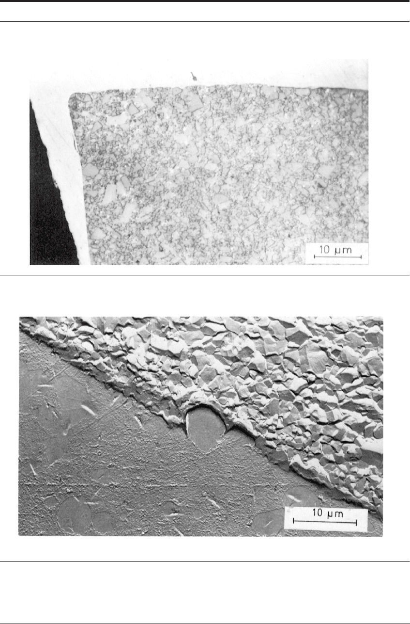
Figure 3.8 is an electron micrograph of a replica of a section through a high speed steel tool at
the rake surface, where the work material (top) was adherent to the tool. The tool had been used
for cutting a very low carbon steel at high cutting speed (200 m min
-1
; 1,600 ft/min). The steel
adhering to the tool had recrystallized and contact between the two surfaces is continuous, in
spite of the uneven surface of the tool, which would make sliding impossible. Many investiga-
tions have shown the two surfaces to be interlocked, the adhering metal penetrating both major
and minor irregularities in the tool surface.
32 THE ESSENTIAL FEATURES OF METAL CUTTING
FIGURE 3.7 Section through cutting edge of cemented carbide tool after cutting steel at 84 m min
-1
(275
ft/min)
7
FIGURE 3.8 Section through rake face of steel tool and adhering metal after cutting iron at high speed.
Etched in Nital; electron micrograph of replica.