Trent E.M., Wright P.K. Metal Cutting
Подождите немного. Документ загружается.

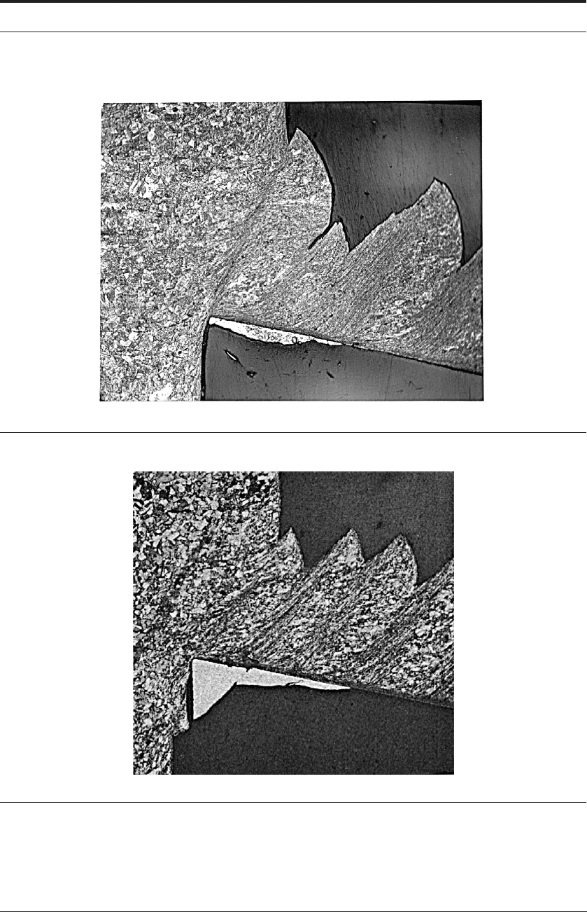
STAINLESS STEEL 353
FIGURE 11.7 Chip formation showing shear initiating at 18
o
on the long shear plane AB
FIGURE 11.8 Chip formation showing shear continuing from the long shear plane AB
B
D
C
A
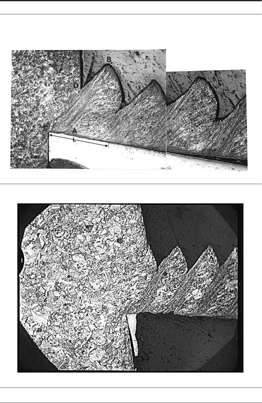
354 HIGH SPEED MACHINING
FIGURE 11.9 Chip formation showing shear finishing up at 30
o
on the short shear plane CD
FIGURE 11.10 Chip formation showing shear temporarily arrested and a compressive bulge
STAINLESS STEEL 355
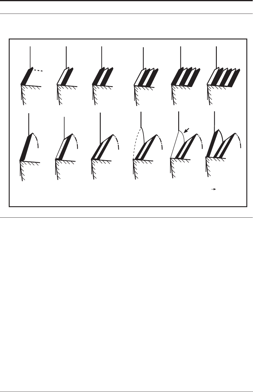
FIGURE 11.11 Schematic diagram of continuous chip formation occurring below 35 m min
-1
and
serrated chip formation occurring above 35 m min
-1
. Lengths CD in the two chip forms are approximately
equal. Also,
cd
approx = 30°, whereas
ab
approx = 18°.
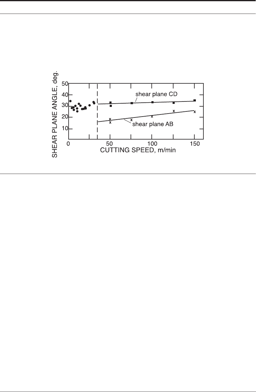
The variation in shear-plane angle has been calculated - both using the equation in chapter 3,
and using the mean minimum and mean maximum chip thickness measured from the serration
dimensions in the photomicographs. These values are shown in Figure 11.12 and are incorpo-
rated with the results from the measurement of in the continuous chip range up to 35 m min
-
1
. The latter have been obtained using the standard weighing and measuring technique that
determines chip thickness and shear-plane angle. The results are of particular interest because it
is the “high shear angle-thin chip-lower energy” situation that does not vary markedly with
increasing speed. Speaking colloquially, it is as if “this is where the chip formation prefers to
operate”.
By contrast, it is the situation which is not initially favored at low speeds but which is trig-
gered at 35 m min
-1
. The observation that the shear plane is intermittently longer (and hence
is smaller) at speeds above 35 m min
-1
is a significant result. Figure 11.12 is thus very relevant
to the mechanism of segmented chip formation. It should be noted that Figure 11.11 has been
drawn to comply with this result, with the length CD of the segmented chip being of equal
length to the shear plane in the continuous chip.
Once the selected shear part of the cycle has reached the shorter plane of length CD, the shear
process is arrested temporarily. The evidence indicates that compressive stresses build up
ahead of the sheared region (ABDC, Figure 11.10) to give a region of uniform low strain at E in
CONTINUOUS
SEGMENTED
A
B
(a)
(b)
E
F
G
(e)
B
(f a)
D
C
D
(c)
C
(d)
E
φφ
φ
φ
356 HIGH SPEED MACHINING
Figure 11.11. There is also prepile-up of the uncut material at F and the continuation of the sec-
ondary shear flow lines at G. The temporary arresting of shear and the compressive stresses are
finally relieved by shear on the long plane AB again, so that Figures 11.11e and f mark the begin-
ning of a new cycle.
FIGURE 11.12 Shear plane angle measurements showing the “high shear angle-thin chip-lower energy”
situation before the “threshold speed” and the “low shear angle-thick chip-higher energy” making its
segmented contribution above 35 m min
-1
.
11.6.3 Conditions in the secondary shear zone when machining stainless steel
In an analysis of the segmented chip formation in austenitic stainless steel, the observations to
be explained are:
(i) the intermittent lengthening of the primary shear plane at speeds above 35 m min
-1
which
continued up to the highest speed that was practically possible. This was 300 m min
-1
and was a
short duration test with a carbide tool.
(ii) the fact that shear does not continue on this plane, so that AB reduces to CD in Figure 11.7
through 11.10. This process precedes the temporary arresting of shear and the build-up of com-
pressive stresses ahead of the tool.
The above observations indicate that for the shear plane to become intermittently lower at
higher cutting speeds, a sticking phenomenon of a periodic nature must be re-introduced in the
secondary shear region. It is proposed, therefore, that a type of stick-slip mechanism develops at
the rake face at high cutting speeds. This means that during the “arrested shear/compression”
part of the cycle, the chip speed is significantly lower than the velocity during the “selected slip”
part of the cycle.
The primary zone was discounted as the source of the large-scale heterogeneity because there
appeared to be no reason for a sudden and intermittent change in the high strain-rate, warm-
working conditions that were established in the continuous chip range up to 35 m min
-1
, at
which speed the temperature in the primary zone was calculated (using the equations in Chapter
5) to be 520°C. The possibility of a large-scale adiabatic shear instability emanating from the
small-scale ones already occurring in the continuous chip type was eliminated by the sudden
increase in length of the shear band at 35 m min
-1
. Futhermore, since the chips remained non-
magnetic, the possibility of a stress-induced transformation affecting the austenitic material in

STAINLESS STEEL 357
the primary zone was discounted. Indeed, a stress-induced transformation would be more likely
in the high strain/low temperature conditions that would occur at speeds much lower than 35 m
min
-1
.
11.6.4 Proposed mechanism for segmented chips in stainless steel
In the secondary shear region the material properties vary dramatically along the contact
length. Material is severely strain hardened in the first part of the contact length but, owing to
the heat generated, temperatures at the very end of the zone can be in excess of 1000°C.
As already discussed, above a strain rate of the shear stress is found to increase sig-
nificantly with strain rate because of the dislocation damping mechanisms which arise; this is
usually termed “Region IV” behavior.
18-21
The approximate secondary shear zone strain rates
have been calculated from the chip speed and zone thickness to give:
= 1.5 x 10
4
s
-1
at 30 m min
-1
and 3.4 x 10
4
s
-1
at 50 m min
-1
.
These values correspond to the beginning and then well into “Region IV” behavior for mild
steel. The authors are not aware of any mechanical test data for austenitic stainless steel at such
high strain rates; but it seems reasonable to assume dislocation damping will be occurring in a
material stronger than mild steel and that the above values are in “Region IV” behavior for
stainless steel.
11.6.4.1 Initiating a “stick” at the threshold speed because “Region IV” dislocation damping
begins
As cutting speed is increased, the value of k
s
jumps substantially, at some critical threshold
speed, as this strain-rate effect “kicks-in”. In the schematic cycle shown in Figure 11.11, the
secondary-zone strain rate is highest when the chip speed is greatest (Figure 11.11c). A conse-
quently high value of k
s
“triggers” the “sticking” part of the cycle (Figure 11.11d).
11.6.4.2 Resuming the “slip” motion after the chip slows down, the strain rate is lessened, and
there is some heat softening in the secondary shear zone
From the above, the material is both strain hardened and strain rate hardened in the initial part
of the contact length, and the associated high value of k
s
“triggers” the sticking part of the
cycle. However, this hardened material is then softened over a short period of time by the heat
retained in the tool and the bulk of the chip. Also, with the slowing down of the chip (Figure
11.11e),
s
and k
s
reduce again to allow the primary zone selected shear to restart at AB. The
reduction in k
s
allows the chip to “slip” away more easily, thus allowing the primary shear to
proceed on a plane of decreasing length (i.e. increasing shear plane angle).
11.6.5 Summary of all the above effects
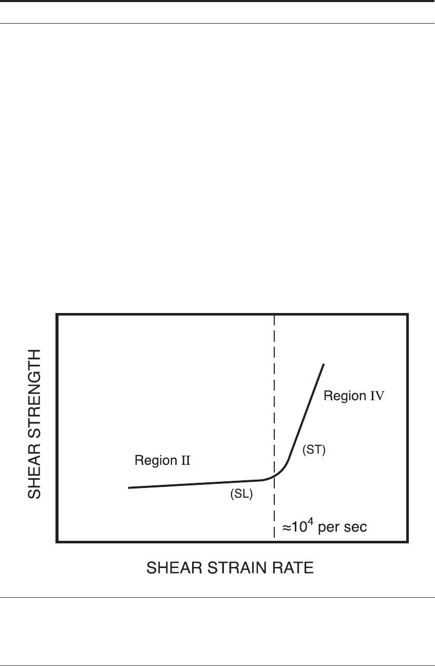
Figure 11.13 is a schematic of the Campbell et al and the Rosenfield and Hahn data on high
strain rate properties.
18-21
Over “Region II” the variation of shear strength with strain rate is
only modest. However, at “Region IV”, dislocation damping triggers a rapid rise in shear stress
with strain rate. Figure 11.2 emphasizes that the primary shear zone of the metal cutting opera-
tion is certainly in “Region IV”. The essential steps are:
γ
·
10
4
s
1–
≈
γ
·
s
γ
·
358 HIGH SPEED MACHINING
Step 1: At some “threshold speed” the material at the front part of the secondary shear zone also
enters “Region IV” behavior. This triggers more sticking friction on the rake face as k
s
suddenly
jumps to position (ST) in Figure 11.13.
Step 2: Chip flow is thus temporarily arrested and a “pile up” or “bulge” forms on the free sur-
face.
Step 3: However, almost instantaneously, because of local heating and since the chip has slowed
down, the conditions are about to return to slipping friction (SL) in Figure 11.13.
Step 4: When something “gives” in the system, the accumulated energy during pile-up means
that the “shear plane has now been pushed down” to only 18
o
for stainless steel.
Step 5: The shear plane “can then return to where it wanted to be”, quickly change in value, and
resume at 30
o
with much less energy.
Step 6: However, this situation is only temporary: the increased chip speed takes the secondary
shear zone material back to (ST) in Figure 11.13 and the cycle keeps repeating on this basis.
This strain-rate dependent mechanism explains why the continuous chips obtained when
machining medium-carbon steel at conventional speeds, also become segmented at ultra-high
speeds. In fact, all materials are expected to enter “Region IV” at some deformation speed,
implying that all materials will eventually machine with segmented chips if the speed is raised
sufficiently high.
FIGURE 11.13 Schematic of strain rate data in “Region II” and “Region IV”.
18-21
At the threshold cutting
speed, the secondary shear zone material enters “Region IV” at (ST). The higher material shear strength
causes “sticking” on the rake face. This impedes chip flow and causes the shear plane angle to segment to
18
o
. An instant later, the secondary shear zone material is weakened by thermal effects and the lower
strain rate. It returns to (SL) and the chip accelerates on the rake face, allowing shear on a shorter plane at
30
o
.

AISI 4340 359
11.7 AISI 4340
11.7.1 Overview
From the 1980’s U.S. Air Force program, Komanduri and colleagues point out that seg-
mented chips are more likely to form in the machining of materials with a limited slip system
(e.g. hcp crystalline structure), poor thermal properties, and high hardness, such as alloy steels,
titanium alloys, and nickel-based super-alloys. In contrast, continuous chips more are likely to
form in the machining of materials with extensive slip system (e.g. fcc/bcc crystalline struc-
ture), good thermal properties, and low hardness, such as conventional aluminum alloys (e.g.
A1 6061-T6) and low carbon steels (e.g. AISI 1018 steel).
11.7.2 Conditions in the primary zone when machining AISI 4340 steel
More recently, Hou and Komanduri
27
modeled the segmented chip forms that they observed
from metallurgical sections to be triggered at 61 m min
-1
in hardened AISI 4340 steel. They
base their analysis on thermomechanical shear instabilities in the primary shear zone. Hou and
Komanduri’s model for how the segments are triggered at a threshold speed is therefore some-
what different from the Sullivan, Wright and Smith model more focussed on the “stick-slip”
effects in the secondary zone. The two models are compared and contrasted in the last section
11.9 of this chapter along with the ideas of other investigators.
Hou and Komanduri note that there are several localized heat sources during chip formation.
And when they are combined, they serve to preheat a large area ahead of the tool. Therefore,
Hou and Komanduri first calculated this temperature in the whole of this “primary shear zone
preheated area”. Second, they calculated the temperature in a “specific shear band between the
segments”. They also calculated the strain in each area. They then applied the following equa-
tion to the two data sets in the two regions.
(11.4)
This equation is a best fit from data in the 1954 ASM Metals Handbook.
28
Note that it does
not, unfortunately contain a strain rate term. Nevertheless, it allows an interesting strategy to be
applied. First, a value of is calculated for the bulk of the preheated material in the overall
general region of the primary shear zone. Second, a value of is calculated for the strength in
a discrete localized shear band.
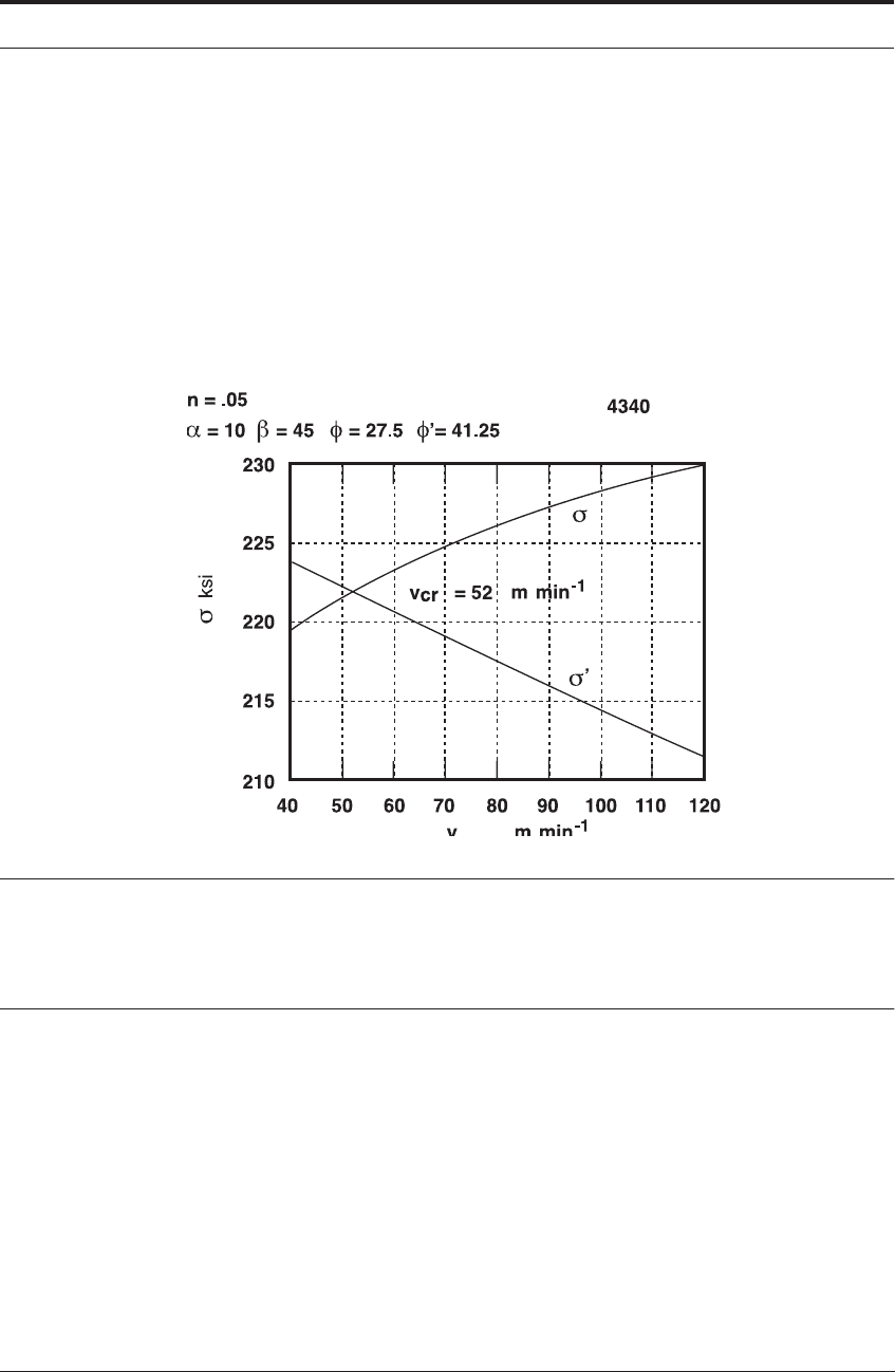
Figure 11.14 shows Hou and Komanduri’s
27
results for the variation of shear stress in the
shear band, , at the shear band temperature and shear strength of the bulk material, , at the
preheating temperature, with increasing cutting speed. The propositions from the theoretical
analysis are as follows:
• When is greater than or equal to , no shear localization takes place, since strain harden-
ing predominates in the shear band. This is the case up to a predicted cutting speed of 52 m
min
-1
.
• Above this speed, thermal softening in the shear band predominates over strain hardening,
i.e. . Hence, shear localization is imminent and segments soon form. This is the case
for predicted values of cutting speed higher than 52 m min
-1
.
σ 432.6572 0.3533T–()ε
0.1213 6.4435
5–
×10 T+()
=
σ
σ'
σ' σ
σ' σ
σ' σ<
360 HIGH SPEED MACHINING
• The intersection of these two curves gives the cutting speed for the onset of shear localiza-
tion.
Experimental results of Komanduri et al.
11-14
showed the onset of shear instability in AISI
4340 at 60 m min
-1
, being complete at 122 m min
-1
- this compares reasonably well with the the-
oretical result that segmentation will be triggered at 52 m min
-1
. Also, in Figure 11.14, the
curves continue monotonically up to high speeds. In Hou and Komanduri’s
27
analysis, this
means that once the transition from a continuous to a shear-localized chip has occurred, no fur-
ther change in chip type is then predicted for any increases of speed up to 1000 m min
-1
. In this
regard, the analytical results well support the experimental observations.
FIGURE 11.14 Hou and Komanduri’s
27
analysis of onset of segmented chips 52 m min
-1
when the
strength of an individual shear band is less than the bulk
11.8 AEROSPACE ALUMINUM AND TITANIUM
11.8.1 Overview
Sandstrom and Hodowany
29
have used the finite element analysis (FEA) computer modeling
techniques described in the next chapter to demonstrate the segmented chips in the high speed
machining of 7050-T7451 aluminum and Ti-6A1-4V mill-annealed ELI titanium. In both cases
their modeling speed was 3, 060 m min
-1
(10, 000 ft./min).
Segmented chips were predicted by their modeling work and were observed in the metallurgi-
cal chip sections from high speed “gas-gun” machining - an experiment similar to Arndt’s
9
and
Recht’s.
6
The “Mach2d” FEA code of Third Waves Systems, Inc., was used. This is a Lagrangian code
that employs dynamic effects, coupled transient heat transfer analysis, and adaptive FEA mesh-
refinement and re-meshing. The code uses a conventional power strain-hardening law (similar to

AEROSPACE ALUMINUM AND TITANIUM 361
the equation in chapter 5) and a power series expansion in temperature for thermal softening.
Very importantly, the code also includes a power viscosity law for strain rate sensitivity. Note
that this viscosity term for strain rate has already been introduced in equation 11.1 as a funda-
mental material constant at high strain rates in “Region IV”.
The importance of including the strain rate effects cannot be emphasized enough. For the alu-
minum alloy, Sandstrom and Hodowany did not obtain satisfactory agreement with experiment
when “standard handbook” data were used. Disagreement was observed both in cutting force
trends vs. cutting speed, and in observed chip morphology. However, these issues were resolved
when they employed experimental shock physics techniques to derive material properties at
high strain rates and elevated temperatures.
11.8.2 Chip morphology of 7050-T7451 aluminum and Ti-6A1-4V titanium
11.8.2.1 7050-T7451 aluminum
The computed effective plastic strain field for high-speed machining of the aluminum alloy
is shown in Figure 11.15. It compares well with an image of an actual machining chip obtained
under corresponding conditions. Once Sandstrom and Hodowany used the high strain rate data
for the aluminum alloy, good agreement was observed both in absolute magnitude of cutting
forces, and in cutting force trends vs. cutting speed.
From the primary zone, the average temperature rise in the bulk of the chip was found to be
about 105
o
C. Similar temperature fluctuations have been experimentally measured during Kol-
sky bar tests of similar materials.
30
Individual values between 120 and 190
o
C were isolated in
the shear localized thinner bands between the segments.
By contrast, in the secondary shear zone, the temperature and effective plastic strain rose
dramatically. At the rear of secondary shear, temperatures approached 660
o
C, approximately to
the melting point, and effective plastic strain exceeded 2,000 percent. The gradient of strain
across the chip is greater than that of temperature because there has been time for heat to diffuse
across the chip and into the tool. In contrast, shear is effectively localized in the secondary
shear zone, resulting in a sharp strain profile.
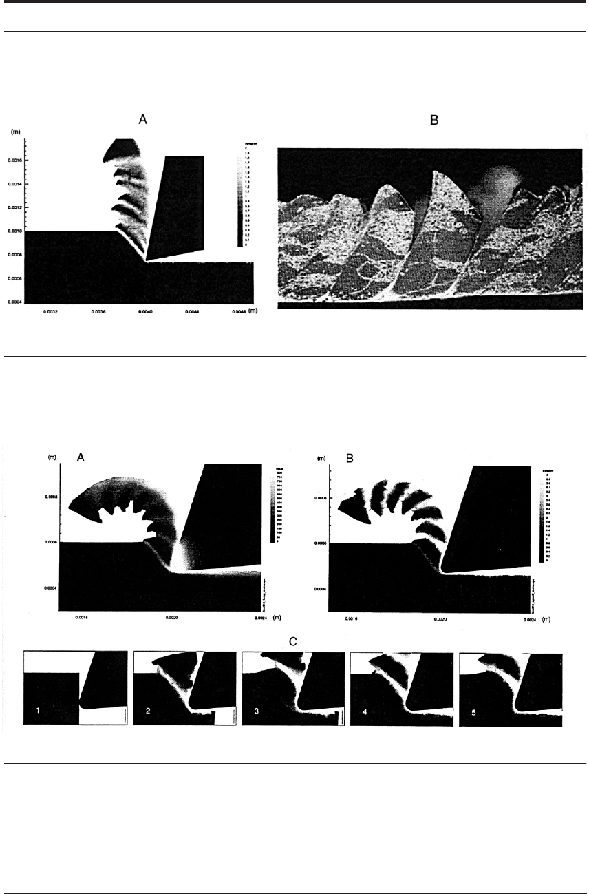
11.8.2.2 Ti-6A1-4V mill-annealed ELI titanium
A similar result for titanium is shown in Figure 11.16. Frame C-1 shows the configuration
before cutting begins. In frame C-2, a shear band is well developed and is being forced up the
tool rake face; the tangential cutting force measured by Sandstrom and Hodowany was on its
way to its peak value. At frame C-3, the material has just begun a new shear instability in the
primary shear zone, relieving stress there; tangential force fell to nearly its minimum value. In
frame C-4 the shear plane of C-3 has become localized and has begun to be forced up along the
rake face; tangential force was again rising.
At frame C-5 shear is arrested but just about to begin again in the primary shear zone. The
system has not yet relieved stresses there - thus tangential force was still at its maximum and
was about to reduce as this shear plane developed. Note that, at an instant after C5, this will be
a “long shear plane of low angle” similar to the Sullivan, Wright and Smith model. Once this
shear band has been initiated, the shear plane gets shorter and the angle is greater. It is as if the
system “prefers” this higher-shear-angle solution but cannot remain there because of the stick-
slip phenomenon.
362 HIGH SPEED MACHINING
FIGURE 11.15 (A) Computed effective plastic strain field for 7050-T7451 aluminum alloy. Cutting speed:
3,060 m min
-1
(10,000 SFM); carbide cutter-rake and relief angles: 11 degrees; uncut chip thickness: 254
m (0.010 inch): orthogonal machining geometry. (B) Metallographic image of machining chip. Machining
conditions same as A
FIGURE 11.16 Modeling results for machining of Ti-6Al-4V mill-annealed ELI. Cutting speed; 10.16 m-
sec
-1
(2,000 SFM); undeformed chip thickness; 127 m (0.005 inch). Cutting tool rake angle: 15 degrees;
relief angle: 5 degrees; tip radius: 25.4 m (0.001 inch). Orthogonal cutting geometry. (A) Field plot of
temperature at end point of model run, corresponding to a cutting time 61.8 sec. Temperature scale in
degrees Celsius. (B) Field plot of effective plastic strain-same time as A. (C) Field plots of effective plastic
strain at successive cutting times: (1) 0.0 sec; (2) 3.6 sec; (3) 7.7 sec; (4) 11.6 sec; and (5) 15.3
sec
μ
μ
μ
μ
μμμ μ
μ