Trent E.M., Wright P.K. Metal Cutting
Подождите немного. Документ загружается.

FINITE ELEMENT ANALYSIS BASED MODELS 383
triangles, rectangles and similar shapes - called subregions or elements - give a piecewise
approximation to the continuum equations. Finite element analysis reduces a continuum prob-
lem with infinite variations to a discretized problem with very large number but a finite number
of unknowns. The roots of the FEA method are often traced to the Courant Institute in New
York.
28
The solution region is first divided into elements. Then the unknown field variable (in this par-
ticular case T) is expressed in terms of an assumed approximating function within each element.
The approximating function - called an interpolation function - is defined in terms of the values
of the field variable at specified corners of the mesh elements - these are called the nodes or
nodal points. The nodal values of the field variable, and the interpolation functions for the ele-
ments, completely define the behavior of the field variable within the elements. For the finite
element representation of any problem, the nodal values of the field variable become the new
unknowns. Once these unknowns are found, the interpolation function defines the field variable
throughout the assembly of elements.
FIGURE 12.8 Continuum approach on the left vs. discretized FEA approach on the right

384 MODELING OF METAL CUTTING
12.5.2 Developing the analysis
(a) Discretize the continuum
: As reviewed by Black
29
the first step is to divide the solution
region into the elements shown on the right of Figure 12.8. A variety of element shapes are used
in the same solution region. The number and type of elements to be used in any given problem
are matters of judgement, experience and trial and error. For example, the authors and colleagues
have studied other metal-processing problems that involve high friction at a tool/work interface.
It was critical to use a very fine mesh at that interface to obtain results in which theory and
experiment matched each other.
(b) Select the interpolation function(s): The next step is to assign the corner nodes to each ele-
ment and then choose the type of interpolation function that represent the variations of the field
variable over the elements. Often, although not always, polynomials are selected as interpola-
tion functions for the field variable because they are easy to integrate and differentiate. The
degree of the polynomial chosen, depends on the number of nodes assigned to the element, the
nature and number of unknowns at each node, and certain continuity requirements.
(c) Express the element properties: The next step is to determine the matrix equations that
express the properties of the individual elements. Four possible schemes are reviewed below: i)
the direct approach, ii) the variational approach, iii) the weighted residual approach, iv) the
energy balance approach.
(d) Assemble the element properties to obtain the system equations: To find the properties of the
overall system, the matrix equation for each element must be integrated with all other matrix
equations in order to finally express the behavior of the solution region or system. The assembly
procedure relies on the fact that, at any node where elements are interconnected, the value of the
field variable must be the same for each element sharing that node. Finally, before the system
equations are ready for solution on the computer, they must incorporate the physics of the
boundary conditions of the problem. For metal cutting they will include friction at the interface
and the temperature conditions at the boundaries of the workpiece, toolholder and free edge of
the chip.
(e) Solve the system equations: The assembly process of the preceding step gives a very large
set of simultaneous equations that can be solved on a computer to obtain the unknown nodal val-
ues of the field variable - in this discussion the temperature T.
12.5.3 Approaches to the finite element analysis (FEA)
The four different approaches to formulating and calculating the properties of individual ele-
ments include:
(a) Direct approach: Structural analysis in civil engineering is the origin of the direct approach
(equation 12.20). This direct approach is based on a direct stiffness method of the structure.
(b) Variational approach: Element properties can also be determined by the more versatile vari-
ational approach. The variational approach relies on the calculus of variations and involves
extremizing the functions. In solid mechanics, the functional turns out to be potential energy, the
complementary potential energy, or a derivative of these.
(c) Weighted residuals approach: A more versatile approach to deriving element properties is
the weighted residuals approach. It begins with the governing equations of the problem and pro-
ceeds without relying on a functional or a variational statement. This allows a finite element
analysis to be used on problems where no functional is available.
FINITE ELEMENT ANALYSIS BASED MODELS 385
(d) Energy balance approach: This approach relies on the balance of thermal and/or mechani-
cal energy of a system. The energy balance approach requires no variational statement and
hence further broadens the possible applications.
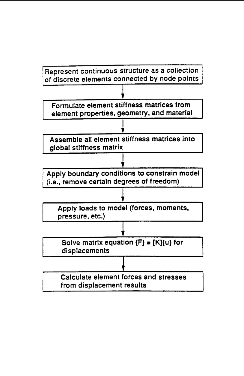
FIGURE 12.9 Overview of finite element solution procedure (Courtesy J.T. Black)
12.5.4 Application of FEA to the specific problem of machining
How do the matrix equations shown near the bottom of Figure 12.9 get solved in a situation
where the tool and work material are in relative motion? As summarized by Athavale and Stren-
kowski,
30
the two basic approaches are the Lagrangian and the Eulerian formulations, together
with an arbitrary Lagrangian-Eulerian formulation.
31

386 MODELING OF METAL CUTTING
12.5.4.1 Lagrangian formulation
In a Lagrangian formulation, the mesh is “attached to the workpiece”. In a virtual sense it
resembles the experiments in which researchers etch a photogrid onto the workpiece and then
study its deformation during cutting. The tool or workpiece is advanced through predefined dis-
placement increments, and the finite element solution is obtained. The displacement increment is
a function of the time step in explicit solution methods.
32,33
This can be related to the material
removal rate during cutting. By contrast, in an implicit solution,
34-37
the time step has no physi-
cal significance. In the various papers in the literature, different material models are used: they
include i) elastic-plastic, ii) only plastic, iii) viscoplastic, and iv) additive
33
as well as
multiplicative
32
decomposition of elastic and plastic strains.
From a civil engineering (structural) viewpoint, the application of finite element analysis for
stress analysis leads to a system equation for the nodal displacement vector
{u} of the system as
follows:
(12. 20)
where
[K] = the global stiffness matrix and
{R} = the load vector which include all its applied loads.
The solution of the system of the equation yields the nodal displacement vector {u} from
which the element strains and hence stresses can be calculated.
By contrast from a metal cutting viewpoint, the assumptions used in the above equation 12.20,
namely small displacement linear analysis and constant material properties, are no longer valid.
In the updated Lagrangian formulation, because the elements move with the workpiece, they
experience both large plastic deformation and rigid body motion. Under such circumstances, the
larger deformations, and the changing material properties due to stress and strain in the material,
need to be considered. The global stiffness matrix [K] is no longer constant. The stiffness matrix
is dependent on the current geometry and the stress history imposed by the loading sequence.
Since the governing equations are now nonlinear, the system must be solved iteratively on the
computer.
The advantage of the updated Lagrangian formulation is that the tool can be simulated from
the start of cutting to a steady-state. One of the disadvantages, however, is that the model
requires large computational times to reach steady-state conditions. In addition, a material fail-
ure and “parting-line or separation” mechanism has to be provided to allow the chip to sepa-
rate from the workpiece.
In the Lagrangian formulation, this “parting-line” or “separation” mechanism of the chip from
the parent workpiece material ahead of the tool tip remains a significant and controversial issue
for researchers. Nodes on this line are separated, and the line “unzipped”, when the tool tip is
sufficiently close, or when a certain level of plastic strain is attained. Various schemes have been
employed as criteria to part the chip: they include effective strain,
34
geometric distortion,
38
and
crack generation and propagation.
39
To implement the chip parting line, several algorithms have
been used: the slide-line,
34
node/element birth and death,
40
and remeshing.
32
K[]u{} R{}=

FINITE ELEMENT ANALYSIS BASED MODELS 387
Obviously, this “unzipping” approach makes assumptions both on the location and stress level
of the “failure”, namely the cutting of the material. Sekhon and Chenot
41
and Marusich and
Ortiz,
32
by contrast, have investigated mesh adaptivity and remeshing to allow for an arbitrary
surface of separation. This approach is much more desirable because it more accurately models
the cutting process. However, it is a time-consuming task to numerically perform the remeshing
and mesh adaptivity and it is still dependent on the material model to correctly describe the
“parting-line failure” in the workpiece just ahead of, or at the very tool tip.
A related problem in a Lagrangian formulation is the computational instability due to the large
distortion of some elements. This problem may eventually cause unrealistic results or premature
termination of the analysis. Severe element distortion also results in a degradation of the accu-
racy. To address this issue it is useful to redefine the mesh system periodically - a process called
rezoning. The rezoning involves the assignment of a new mesh through interpolation. The capa-
bility of rezoning has been included in many finite element codes for large displacement, large
strain, plastic deformations.
42
12.5.4.2 Eulerian formulation
In the Eulerian formulation, the workpiece material is assumed to flow through a meshed con-
trol volume - the cutting zone. This Eulerian viewpoint focuses attention on a particular point in
space and then examines the phenomena occurring there.
The cutting process is treated as a large deformation process involving a viscoplastic material.
It is assumed that elastic effects are negligible. Therefore, the constitutive law becomes a vis-
cous flow equation relating flow stress to the instantaneous strain rates.
(12. 21)
where
= the viscosity which is dependent on the strain rate
The global matrix for all elements in the chip and workpiece is found by summing the contri-
bution for each element. This results in the following equation:
(12. 22)
where
[K] = the global stiffness matrix
{U} = the nodal velocities
{P} = the vector of all applied nodal loads
There are three iterative cycles that are performed during this simulation:
(1) The first involves solving the viscoplastic equation for velocity and strain-rate distribution
in the chip and workpiece. An estimate of the strain-rate is initially used to calculate the viscos-
ity at ambient temperature conditions. After each iteration, the strain-rate is compared to the ini-
tial value. The iterations are continued until the initial and calculated strain-rate converge.
σ{} C μ(){}]ε
·
{}[=
μ
K[]U{} P{}=

388 MODELING OF METAL CUTTING
(2) Once the velocities have been determined, the temperature is calculated. Because, in gen-
eral, the thermal properties of both the workpiece and tool will depend on the temperature, an
iterative solution is again required until the temperatures converge.
(3) The final step consists of updating the chip geometry to ensure that the computed velocities
on the chip surfaces are parallel to the free surfaces. As Athavale and Strenkowski
30
point out,
one disadvantage of the Eulerian formulation is that the boundaries of the chip free surface i)
need to be known in advance and ii) also need to be adjusted iteratively during the simulation.
This issue can be addressed in an updated Eulerian approach as follows. At the end of each
iteration step the calculated velocity field is integrated. Then, the displacement obtained can be
used to create a new geometry, which defines the next Eulerian step. During such calculations,
the free surface of the chip, and the chip shape, must be determined explicitly. Also, the work-
piece velocities must be determined explicitly. The incoming bulk workpiece velocity must
obviously be tangential to the element sides that represent the external physical boundaries of
the free surface of the workpiece and newly forming chip. Similarly, the two boundaries of the
formed chip - one along the rake face and the other opposite on the chip’s free surface - must be
repositioned iteratively. The repositioning of these two chip boundaries may be independent
43
or
dependent.
37
Also note that for the Eulerian formulation, the strains have to be computed from
the strain-rates by integrating along stream lines. Thus the basic method is not applicable to a
discontinuous workpiece that the tool would cut in an interrupted fashion. Space-time Eulerian
formulations
44
are being developed for discontinuous workpieces, discontinuous chips and seg-
mented chips and these will see further uses in the future.
12.5.4.3 Summary
Despite these challenges, the main advantage of the Eulerian formation is that it eliminates the
need for an explicit material failure or separation criterion. For Eulerian models, the chip parting
criteria occurs at the stagnation point at the tool tip. And this is obtained from the velocity distri-
bution. Further, physical separation of the chip and workpiece nodes are not required, since the
mesh is not attached to the workpiece surface.
12.5.5 Brief historical perspective of FEA use in metal cutting research
The reader is first referred to a comprehensive review by Chen and Black.
45
This contains most
of the significant citations up to the early 1990s. Second, the collection of papers edited by Jawa-
hir, Balaji and Stevenson
46
contains contributions from many of today’s investigators in the FEA
area.
The earliest papers appeared in 1973. Klamecki
47
analyzed the stress state transition from
plane stress at the workpiece surface to plane strain in the central region of the shear zone, and
Tay et al
27, 48-50
presented a two-dimensional model of the temperature distribution generated
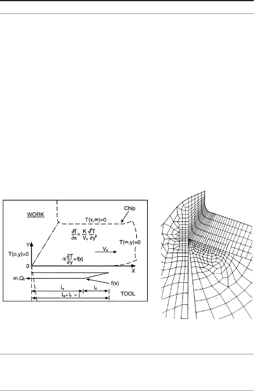
during orthogonal machining. It used the following two-dimensional energy equation,
27
for the
heat conduction and convection:
(12. 23)k
t
∂
2
T
∂x
2
---------
∂
2
T
∂y
2
---------+
⎝⎠
⎜⎟
⎛⎞
ρC
p
U
x
∂T
∂x
------
U
y
∂T
∂y
------
+
⎝⎠
⎛⎞
– q
·
+0=

FINITE ELEMENT ANALYSIS BASED MODELS 389
where k
t
is the thermal conductivity, is the density, is the specific heat, T is the tempera-
ture and is the volumetric heat generation rate.
The following boundary conditions apply:
T = T
s
on a surface S
T
where T is defined,
on a surface S
q
where q is defined.
(T - T ) on a surface S
h
where is h is defined.
By the late 1970s, Tay, Stevenson, de Vahl Davis and Oxley
49,50
had successfully adapted the
analysis to avoid the need for a flow field as input, partly based on Stevenson and Oxley’s ear-
lier work.
49
Also, a basic mesh for a given tool geometry was automatically adjusted for shear
angle and contact length over wide range.
Stevenson, Wright and Chow
51
also used the tool etching method described in Chapter 5 to
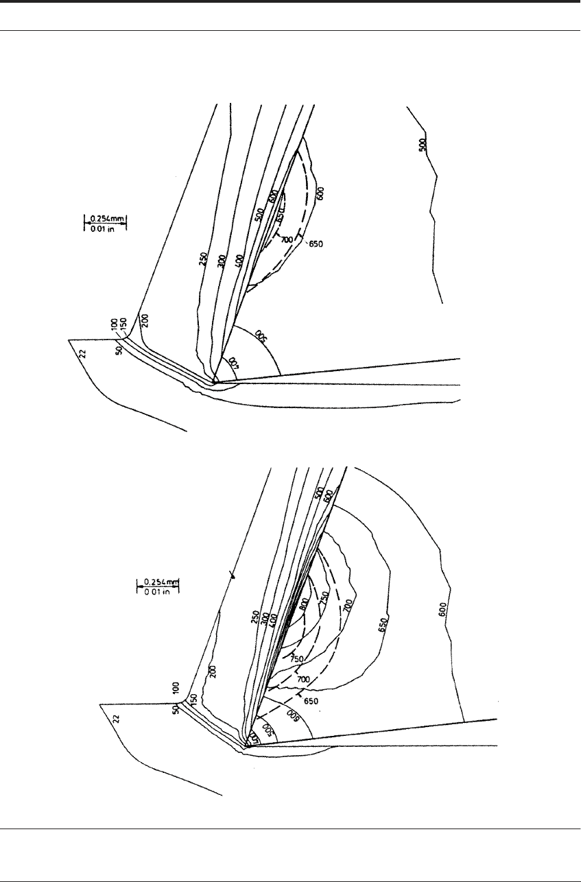
verify the FEA predictions. Figure 12.10 shows very good agreement, with a discrepancy
between experiment and calculation of only about 50°C, although in this case the calculation
gives the higher temperatures. Also, the isothermals of the calculation in the second case are dis-
placed along the rake face from those of the experiment, suggesting an error in the measurement
of the contact length used as input to the calculation.
Such an error could also have arisen from the formation of the crater. The contact length scar
which was measured on the tool may have resulted from the early period of the cut before the
crater formed. Formation of the crater would promote chip curl and gradually reduce contact
length as the cut continued.
Also in the late 1970s, Muraka, Barrow and Hindjuka
52
published a finite element analysis for
calculating the temperature distributions in orthogonal machining. They used the same govern-
ing equation and boundary conditions as Tay et al., and obtained the solution by using the Galer-
kin method.
The effects of coolant on temperature distribution in metal cutting were then studied both
experimentally and theoretically by Childs, Maekawa and Maulik,
53
using an analysis similar to
that of Tay et al. An interesting conclusion reached, compatible with the findings in Chapter 10,
was that the effect of coolant was least on the rake face, greater on the flank face and greatest on
the tool and tool holder.
In related work, Maekawa, Nakano and Kitagawa
54
found that the use of a high-thermal-con-
ductivity tool such as diamond, was more effective in reducing the rake temperature than the use
of a coolant. This tendency became more obvious when a low-thermal-conductivity material
such as a titanium alloy was machined.
ρ C
p
q
·
k
t
∂T
∂n
------
– q=
k
t
∂T
∂n
------
h=
∞
390 MODELING OF METAL CUTTING
FIGURE 12.10 Experimental results from the tool etching method (dashed lines) in Chapter 5 and the
corresponding FEA predictions Cutting speeds:61 m min
-1
and 106 m min
-1
FINITE ELEMENT ANALYSIS BASED MODELS 391
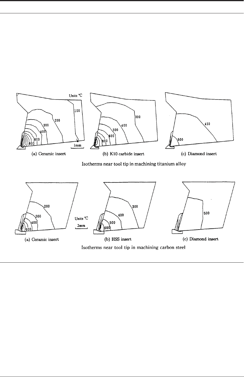
For example, Figure 12.11a shows the steady cutting temperature when machining the tita-
nium alloy in air using a) ceramic, b) carbide and c) diamond tools. Figure 12.11b shows a sim-
ilar result for machining medium-carbon steel. The intervals of isotherms in both figures are
100°C. The cutting temperature for the titanium alloy is higher for every tool type, even though
a low cutting speed and feed was set as compared to the steel machining. An interesting result is
that the edge temperature for the ceramic tool, whose thermal conductivity is the lowest, mark-
edly increases to as high as 1300°C.
FIGURE 12.11 Maekawa et al.’s calculated isotherms near tool tip a) above: when machining titanium
alloy b) below when machining medium-carbon steel
12.5.5.1 Lagrangian examples
Following the early FEA-machining papers of the 1970s, both Lagrangian and Eulerian
approaches have been developed over the last twenty years.
In 1991, for example, Komvopoulos and Erpenbeck
55
used the general purpose code
ABAQUS and an updated Lagrangian formulation. A distance criterion was used as the chip
separation criterion. They investigated two possible constitutive deformation laws: i) elastic-
perfectly plastic (EPP) and ii) elastic-plastic with isotropic strain hardening and strain rate sensi-
tivity (EPSHR). Unworn and worn (cratered) tools with strongly adherent built-up edges were
used for comparison. A total of five finite element simulations with different material models,
different friction coefficient values and different tool geometries were studied to find their
effects on the cutting process. Coulomb’s law was used for the modeling of the tool-chip inter-

392 MODELING OF METAL CUTTING
face friction - the reviews of the seizure conditions in Chapters 4 through 9 indicate that their
results could still be re-run with different boundary conditions and some new insights will
emerge.
Lin and Lin
56
also developed a thermo-elastic-plastic finite element model based on the
updated Lagrangian formation and the Prandtl-Reuss flow rule. A strain energy density was used
as the chip separation criterion. This is a material constant representing the energy absorption
capability, and was determined from a uniaxial tensile test.
12.5.5.2 Eulerian examples
In 1990, Strenkowski and Moon
57
employed an improved Eulerian model. In this modified
version, a separate procedure was used to predict the chip geometry and chip/tool contact length.
The chip geometry was predicted by requiring that material velocity normal to a free surface be
zero. This method was originally proposed by Zienkiewicz et al.
58
Once the chip geometry was
determined, the contact length was predicted by checking the normal stress at every node along
the tool-chip interface. A positive normal stress at any node along the interface meant that this
particular node had been released from the tool/chip interface. The predicted contact length was
then determined and used to modify the thermal conduction path between the chip and the tool.
Also, Strenkowski and Hiatt
59
coupled the stresses resulting from the improved Eulerian
model with a fracture mechanics model proposed by Broek.
60
It allowed the prediction of the
ductile regime in a single point diamond turning operation on a brittle material. In further work,
Strenkowski, Larson and Chern
61
coupled the temperatures resulting from the improved Eule-
rian model with a tool-wear by diffusion model. In this work, thermal infinite elements were
used for the flow zone in secondary shear. The infinite element
62
differs from the standard finite
element because one of its edges is made to extend to infinity - such an element geometry is use-
ful for unbounded field problems. Given the nature of the flow zone (e.g. a thin zone where
shear strains are between 20 and 50 - see Chapters 4 and 5) the use of an element which is very
long and thin has great intuitive appeal. Once Strenkowski et al. had calculated the temperature
distributions in such a way, the depth of the diffusion wear along the tool rake face was then
determined from the diffusion coefficients.
12.5.6 Case study I: modeling chip-breaker grooves
Jawahir and colleagues developed an Eulerian formulation that followed the Hu-Washizu vari-
ational principle.
63
The global stiffness matrix was based on equation 12.22 in the earlier sec-
tion, and similarly the constitutive equation was:
(12. 24)
where is the effective stress, is the strain-rate and temperature dependent viscosity
and is the strain-rate. The thermal effects were developed from the same 2-D
equation as Tay et al’s.
The model also included the chip-groove on the tool rakeface. The boundary conditions used
for the deformation analysis and the thermal analysis are shown in Figure 12.12.
First, the normal component of the velocity at the tool-chip interface is set to be zero.
Second, a frictional, tangential stress is prescribed at the tool-chip interface and the groove back-
wall. In the “controlled contact” or land region - see Figure 4.11 - it is assumed that the chip is
σμε
·
=
σμ
μμσε
·
T ε,,,()=
ε
·
U
x
()