Trent E.M., Wright P.K. Metal Cutting
Подождите немного. Документ загружается.

FINITE ELEMENT ANALYSIS BASED MODELS 393
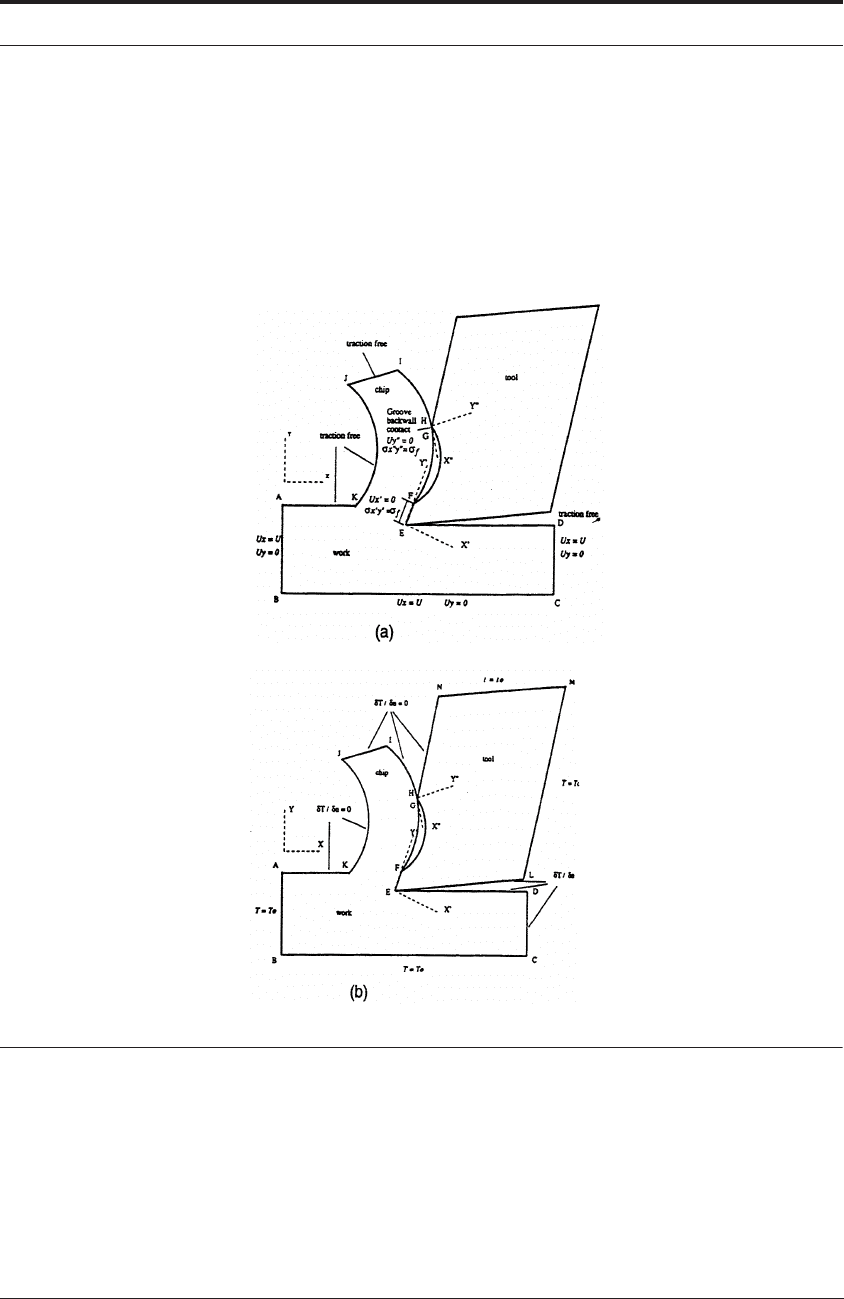
initially in entire contact. The normal stress at the nodes is calculated and it is assumed that the
tool and the chip are in contact as long as the normal stress is compressive - similar to Stren-
kowski and Moon’s work. A similar procedure is followed for the groove backwall. Thus, the
tool-chip contact length is determined after the computational iterations. The friction on the
“controlled-contact” land is divided into regions of sticking and sliding friction. Coulomb fric-
tion is assumed at the groove backwall.
FIGURE 12.12 Boundary conditions for (a) deformation analysis; and (b) thermal analysis
63
12.5.7 Case study II: finite element analysis of stresses in the tool
Kistler and colleagues carried out an investigation to calculate the stresses in a cutting tool
and then compared the results with the experiments of Bagchi and Wright described at the end
of Chapter 4.
The problem was essentially two dimensional, with nodes being restrained in the “depth”
direction. The geometry and mesh for the figure below were created using MSC/PATRAN
64,65

394 MODELING OF METAL CUTTING
before an ABAQUS version 5.4 input file was created. The mesh was oriented in the direction of
the movement between tool and workpiece. The analysis deck created by MSC/PATRAN for
ABAQUS was edited to modify material parameters for use with a “damage/plasticity model
65
and to set the problem up to use a conjugate gradient analysis technique. Post-processing was
performed by ABAQUS.
The “damage/plasticity model”
65
was a material model which accounted for the deviatoric
deformation resulting from the presence of dislocations and dilatational deformation and ensu-
ing failure from the growth of voids. This model allowed the calculation of accumulated damage
in a finite element. The capability of the ABAQUS finite element code was used to turn finite
elements “off” when a user-defined parameter level was reached in each element. This elimi-
nated elements which otherwise would have had large distortions (causing convergence prob-
lems in the analysis) but which physically had failed or had lost their load carrying capability.
This adequately represented the cutting/failure/chip formation mechanisms without requiring
remeshing or mesh adapting. As in all the experiments reported in Chapter 4, the highest normal
stresses were localized at the cutting tip. The analytical stresses in the cutting direction com-
pared well with the corresponding experimental stresses Figure 12.13. The most notable differ-
ence between two stress profiles was that the spatial gradient of the stress magnitude decreased
more quickly with distance in the finite element analysis. Kistler attributed this difference to the
effects in the chip tool contact area. The FEA assumed frictionless conditions for convenience,
and calculated a contact length of 0.58mm. In the experiments, the contact length was 0.85mm.
These different values of contact length almost certainly account for the differences in the nor-
mal stress profile.
12.5.8 Case study III: cutting temperature of ceramic tools
El-Wardany, Mohammed and Elbestawi carried out investigations into the different factors
which influence the temperature distribution in A1
2
0
3
-TiC ceramic tool rake face during
machining of difficult-to-cut materials, such as case hardened AISI 1552 steel (60-65 Rc) and
nickel-based superalloys (e.g. Inconel 718). A commercially available finite element program
(ALGOR) was used to calculate the temperature distributions.
66
Temperature measurements on
the tool rake face were performed using a thermocouple based technique and the results com-
pared with the finite element analysis. Experiments were then performed to study the effect of
cutting parameters, different tool geometries, tool conditions, and workpiece materials on the
cutting edge temperatures.
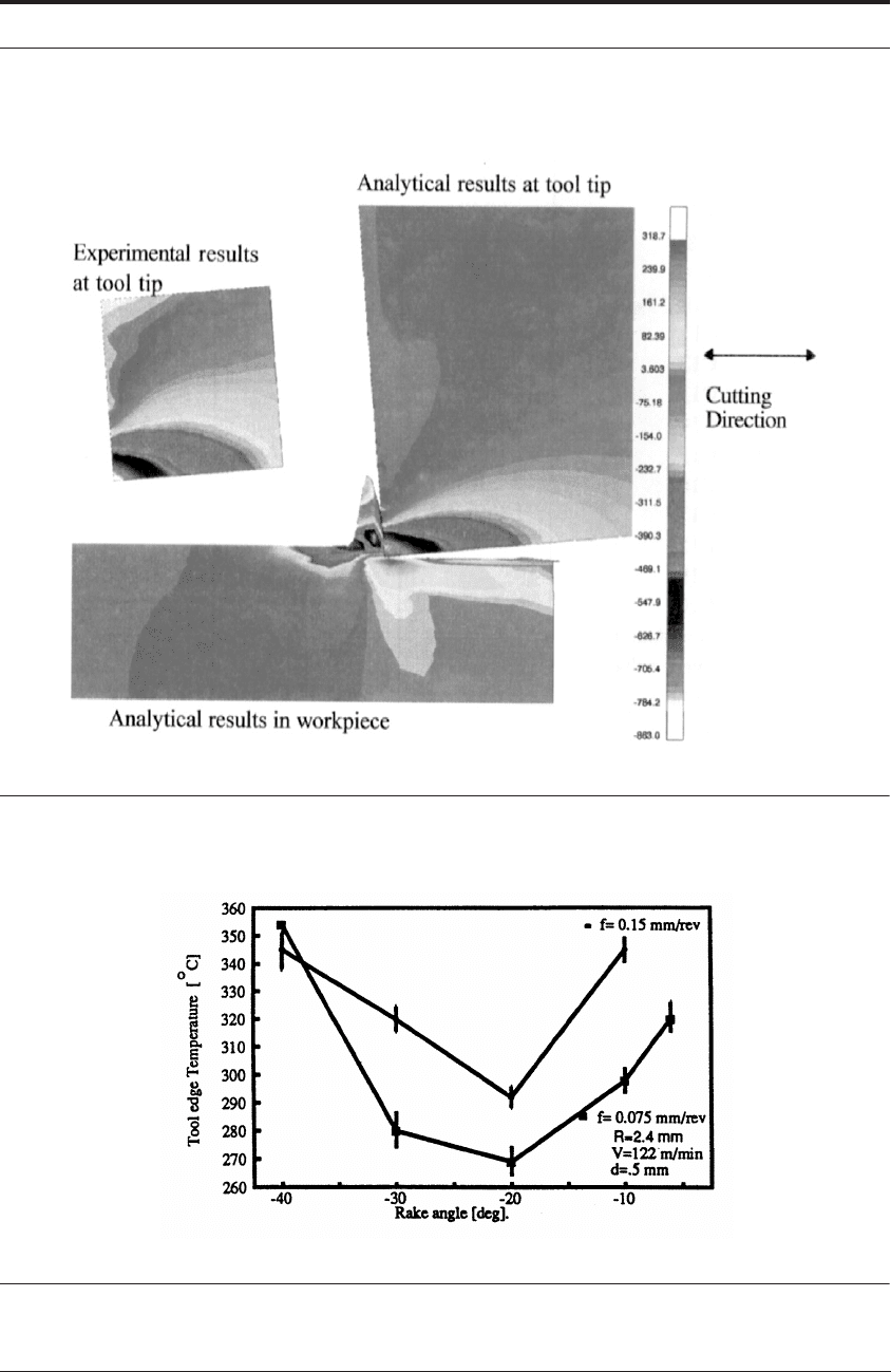
Of particular interest, it was found that there is an optimum value of rake angle where the cut-
ting edge temperature was minimum. Details are given in Figure 12.14. Initially the edge tem-
perature reduced with a “more negative rake angle” from -6° to -20°; but beyond -20°, to even
more negative values, the temperatures increased again. The same trend was obtained even for a
higher feed of 0.15 mm/rev. El-Wardany et al provide the following explanation: At -6° rake
angle the “air-gap” between the tool’s clearance face and the cut surface is relatively small.
Moving from -6° to -20° rake angle, the tool gets “rotated/lifted up” away from the surface and
there is a greater chance of cooling by convection. But eventually, the shearing of the material in
the secondary shear zone gets to be so intense with more aggressively negative rake angles, that
the overall heat generated is larger and temperatures rise again.
FINITE ELEMENT ANALYSIS BASED MODELS 395
FIGURE 12.13 Comparison of cutting direction stress (MPa) with Bagchi and Wright’s experiment
FIGURE 12.14 The effect of (negative) rake angles on cutting edge temperatures during turning of
hardened steel at V = 122 m min
-1
, d = 0.5 mm, R = 3.2 mm and f = 0.075 mm/rev.

396 MODELING OF METAL CUTTING
12.5.9 Case study IV: finite element analysis of burr formation in 2-D orthogonal cutting
Park and Dornfeld
67
developed a finite element model of burr formation in 2-D orthogonal
cutting using plane strain assumptions and investigated the influences of various process param-
eters. A general purpose FEM software package, ABAQUS, was used to simulate the chip and
burr formation processes, especially the transition from steady-state cutting to burr formation on
tool exit. An adiabatic heating model was adopted to simulate the heat generation effects due to
plastic work of the workpiece and chip. Also, based on a ductile failure model in ABAQUS, the
metal cutting simulation procedure was developed to separate the chip from the workpiece and
to give a final burr/breakout configuration. The burr formation mechanism is divided into four
stages: initiation, initial development, pivoting point, and final development, Figure 12.15. The
initiation stage represents the point where the plastically deformed region appears on the edge of
the workpiece. In the initial development stage, significant deflection of the workpiece edge
occurs, and a bending mechanism initiates burr formation. In the pivoting point stage, material
instability occurs at the edge of the workpiece. A burr is further developed under the influence of
a negative deformation zone ahead of the tool. Hence, plastic bending and shearing are the dom-
inant mechanisms in this stage. However, if the material cannot sustain highly localized strain in
front of the tool edge, then fracture is initiated and leads to the edge breakout phenomenon.
The influence of exit angles of the workpiece, tool rake angles, and back-up materials on burr
formation processes in 304L stainless steel were investigated. The burr formation mechanisms
with respect to five different exit angles were found, and the duration of the burr formation pro-
cess increases with an increase of exit angle, resulting in different burr/breakout configurations.
Also, with fixed cutting conditions and workpiece exit geometry, the influence of the rake angle
was found to be closely related to the rate of plastic work in steady-state cutting because the
larger the rate of plastic work in steady-state cutting, the earlier the burr initiation commences.
In order to effectively minimize the burr size, three cases of back-up material influence on burr
formation processes were also examined. It was found that the burr size could be effectively
minimized when back-up material supports the workpiece to just below the pre-defined
machined surface.
FIGURE 12.15 Comparison between finite element simulation (top) and SEM (bottom) pictures of burr
formation mechanism in 2-D orthogonal cutting

ARTIFICIAL INTELLIGENCE BASED MODELING 397
12.5.10 Summary
The first Case Study based on Jawahir et al.’s FEA work shows that it will be possible to
model different styles of chip-breaker and hopefully optimize their geometry for minimum tem-
perature and prolonged tool life.
Similarly, Kistler and colleagues confirm that the FEA methods allow a detailed study of the
normal stresses on the tool. A promising area for future work, is to re-run the analyses on geom-
etries such as those shown in Figure 8.2 for ceramic tools. The FEA methods allow a wide vari-
ety of such cases to be investigated once they have been checked against experiment - such as
the transparent tool work for stress and the tool etching method for temperature.
The third Case Study indicates that there may well exist an “optimum” negative rake angle for
minimum temperature when turning hardened steel.
The fourth case study allows burr height and depth to be related to cutting conditions.
12.6 ARTIFICIAL INTELLIGENCE BASED MODELING
12.6.1 Overview of basic concepts in artificial intelligence
The last two main sections highlight the mathematical sophistication of the mechanistic mod-
els and the FEA-based models. Furthermore, the case studies show their great potential for the
future design of cutting tool geometries. Nevertheless it is clear that they still rely on empirical
testing for frictional boundary inputs and material properties at high strain rates. Also, the mod-
els are complex in nature and the best of the FEA models - the Eulerian models with remeshing
- are very time consuming to run on today’s computers.
It is therefore not surprising that many other modeling approaches have been attempted. These
include neural network approaches, genetic algorithm approaches and artificial intelligence (AI)
based approaches. The last of these, AI-based modeling is considered in this section.
Artificial Intelligence is an area of computer science that attempts to re-create human intelli-
gence “inside the computer”. Thus for metal cutting, an AI-based model attempts to re-create
the skills and expertise of a manufacturing craftsperson. The desired outcome is that a computer
controlled CNC machine tool can be set up and then operate itself without human intervention.
In essence, the goal is to create an “intelligent, self-monitoring and self-diagnosing” CNC
machine tool.
Knowledge Engineering is a sub-field of AI in which computer scientists interview skilled
craftspeople and codify rules that express the craft-oriented knowledge. At the highest level, the
goals are to capture the general procedures, methods, and generic skills of the field. At the low-
est level, highly detailed “If...then” rules are captured and encoded in a computer base.
Expert Systems contain the rules that are gathered during knowledge engineering. They con-
tain many hundreds of rules, many of which can be highly quantitative. By contrast, some
important rules can only be expressed in qualitative terms. For example, a machinist might say
to a knowledge engineer, “I will keep increasing the cutting speed in 10% increments if the
chips are silver colored and watch them until they are light-to-dark-blue”. In this case there is no
quantitative data on the specific temperatures involved. But this “rule of thumb”, formally
called a heuristic, contains very valuable information on the trade-off between productivity and

398 MODELING OF METAL CUTTING
tool life. Namely, if the chips are silver in color, the cutting speed is probably “too safe” and the
machine is not making parts profitably. But if the chips are beyond dark-blue and then purple,
the speed is probably “too high”, tool life will be short, and again profitability will suffer. Vague
as these color labels are, if the expert system contains an “If...then” table that captures this infor-
mation it can be used to run the machine tool within “safe but productive” limits. One criticism
might be that different machinists, based on their personal experiences, will give slightly differ-
ent information in the above scenario. This generally means that careful knowledge engineering
garners many different people’s view, tries to average them as best possible, and then compares
the predictions from the expert system with the predictions from the best craftspeople available.
The research of Bourne, Hayes and the authors is mentioned here for further citations in the
application of artificial intelligence to manufacturing.
5,68
12.6.2 The role of the expert machinist
Given this brief introduction, the AI-based modeling approach asks this simple question: How
does a skilled craftsperson set up a machine tool, choose the cutting conditions, and then moni-
tor the operation for a successful outcome? Once the question has been answered and the
detailed steps codified the model can be put to use. The approach is so deceptively simple, that it
is often criticized as “just being a great deal of common sense” based on simple observations of
what people do on a day-to-day basis in a factory. But given the complexity of all the other mod-
eling methods in this chapter, it is an interesting and thought-provoking procedure to review.
In today’s factory situation the general way of setting the cutting conditions is as follows:
12.6.2.1 Step 1: carry out general planning
Consult the CAD/CAM files to identify the following main considerations: i) the precise mate-
rial specifications (including hardness and heat-treatment), ii) the desired part tolerances and
surface finishes, iii), any “unusual features” on the part that might require special fixturing and
iv) the batch size.
12.6.2.2 Step 2: select tooling type in relation to batch size
Select the cutting tools that will be used based on batch size. Recall from the summary in
Chapter 8, that in a “job-shop” setting, high speed steels are likely to be the most convenient
choice. By contrast, in a high volume automobile manufacturing situation, carbide and ceramics
are the desirable choice.
12.6.2.3 Step 3: select specific process and the tools that go with them
Identify the specific cutting processes that will be used to obtain the specific part features
needed. Ideally, the part can be made with straight-forward milling, turning and drilling opera-
tions so that unusual fixturing, tooling and set-ups will not be needed. But in some cases, deep
features will make end-mills vibrate and require a much reduced cutting speed. Or a slot in a part
will require the stock to be “hanging-out” of a vise, again prompting a reduced cutting speed.

ARTIFICIAL INTELLIGENCE BASED MODELING 399
12.6.2.4 Step 4: pick the first round of speeds and feeds in the “Machinability Data Handbook”
Consult Metcut’s Machinability Data Handbook, for the recommended cutting speeds and
feeds for this particular material’s composition and heat-treatment. The Handbook, specializes
in tables for the different cutting tool types and the different cutting processes (e.g. end milling
vs. face milling vs. turning) described in Steps 2 and 3 above.
12.6.2.5 Step 5: modify the chosen speeds and feeds based on part tolerances
Review the recommended conditions based on the tolerances needed. In today’s economically
competitive environments, focusing on high quality, it is quite likely that tight tolerances and
very good surface finish are being specified. This means that both “roughing” and “finishing”
passes will be selected. Each of these will demand different speeds and feeds.
12.6.2.6 Step 6: modify the chosen speeds and feeds based on surface finish
The surface finish is a direct function of the tool’s nose-radius and the feedrate. It is thus likely
that for the finishing pass the feed rate will be reduced to obtain the desired surface finish and
then the speed will be increased to maintain productivity.
12.6.2.7 Step 7: begin the roughing and finishing passes on the machine tool
Cutting can begin once the fixturing and tools have been assembled into the machine tool. It is
clear from all the steps above that many iterations have already been made but that the condi-
tions may still be too conservative. As mentioned earlier in the chapter, the Machinability Data
Handbook usually sets conservative bounds on the problem so that “no surprises” will arise
when cutting actually begins. Thus the CNC programmers or the machinist will watch the first
few parts coming off the machine and make adjustments where desirable. Recall at the end of
Chapter 3, Figure 3.30, the machinist will be watching and listening for many trends and signals
from the machining operation. During roughing, the desire is to remove material fast - chip
color is often the best guide. During finishing, the desire is to obtain a smooth finish - the visual
condition of the surface is monitored in real-time and then checked with a profileometer.
12.6.3 Information in the AI-based model and expert system
Clearly, a big part of this approach relies on the quantitative information in the Machinability
Data Handbook. For the other information, the AI-based model simply documents the above
steps and as much as possible “fills-out” a supplementary expert system with “If...then” rules.
Some rules might still be quite quantitative. Boothroyd,
69
and others, have derived expressions
relating the feed per tooth (f), and the tool radius (R), to the center-line average roughness, R
a
.
From purely geometric considerations, the ideal surface roughness is given by:
(12. 25)
Here, a “look-up-table” can be created containing this information with some supplementary
heuristics that might relate, say, to coated vs. uncoated tool materials where the former might
give a further improvement on smoothness. Other information on what percentage the speed
R
a
0.0321 f
2
R⁄()=

400 MODELING OF METAL CUTTING
should be reduced for a “part/fixture overhang” or a “deep-pocket/long-tool situation” will be
much more heuristically based.
12.6.4 Case Study: AI-based modeling of “best speed and feed”
When a skilled machinist begins the first roughing pass, the hope is that the Machinability
Data Handbook values of speed and feed are “safe but productive”. Analogically, the machinist
is searching for the “cruising speed” for the cut where there is a nice balance between high rate
part output but not too much tool changing and re-setup.
At first, the machinist will make sure that the correct grade of cutting tool has been chosen.
There are always situations where the chosen tool is too brittle and a catastrophic failure occurs
when the first part is cut. There is no choice but to substitute a new tool grade from the charts in
Chapter 7, Tables 7.3.
Eventually the machining will “settle down” and then the machinist will carry out fine-tuning
adjustments. The goal is to “push the chosen tool into the safe but productive region” as
described in the following AI-based model. A machinist knows that the rate of metal removal for
any of the particular tooling types is set by the “collapse of the cutting edge”. This is an instanta-
neous version of the wear by plastic deformation of the tool edge shown in Figure 6.24, diagram
#2. It occurs if the local stress and temperature in this region exceed the hot compressive yield
strength of the tool material in the vulnerable cutting edge region. A skilled machinist tries to
judge this by chip color and vague intuitions about the stress on the edge from vibrations and
tooling deflections. However, these are understandably very intuitive and not based on measured
temperatures or stresses. The analysis below focuses on these measurements and their correla-
tions with the tool condition.
12.6.5 A “fail-safe” diagram
To illustrate the AI-based model, the plastic deformation of the cutting edge is now analyzed in
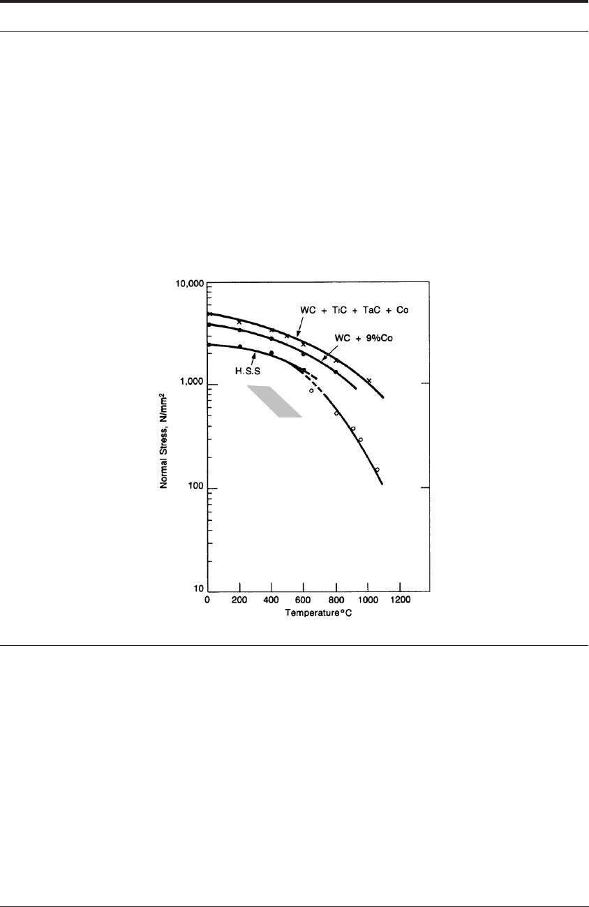
more detail. Figure 12.16 presents laboratory compression tests on different tool materials.
These plots show the relationship between the yield strength and temperature. However, Figure
12.16 should be viewed as more than just the physical properties of the tool materials presented
in a way commonly found in Handbooks. It also represents a “fail-safe” diagram for the edge of
a cutting tool made from one of the materials. A point in the lower left space, below the curves,
represents a safe condition where the tool edge will not yield and plastically deform. Conversely,
a point in the top right area, above the curves, represents a condition where the materials will
yield and deform. Ideally, the cutting speed and feed rate need to be adjusted so that the temper-
ature and stress values of the tool’s cutting edge are in the safe region. However, operating con-
ditions cannot be “too safe.” To machine and produce parts quickly, the speed and feed rate, and
consequently temperature and stress, must be pushed into the “safe but productive” shaded
region, just under the curves in Figure 12.16.
Whether or not the tool is operating in this “safe but productive” region is controlled by the
cutting conditions that the machinist or manufacturing engineer selects. For a constant depth of
cut d, the functional relationships between the control input variables speed V and feed rate f,
and the physical state variables temperature T and stress may be summarized as:
σ
ARTIFICIAL INTELLIGENCE BASED MODELING 401
(12. 26)
(12. 27)
Where K represents the thermal properties of the tool material; is the shear plane angle;
is the tool rake angle; V and f are speed and feed; is the shear strength of the workmaterial
being cut; and A, B, and C are constants.
FIGURE 12.16 Elevated temperature yield strength of tool materials. The shaded area is the “safe-but-
productive” region for temperature and stress, when machining with high-speed steel. The top two curves
are for cemented carbide tools made from tungsten carbide (WC), titanium carbide (TiC), and tantalum
carbide (TaC), cemented together with cobalt (Co). The lower curve is for high-speed steel (HSS.). From
Wright and Bourne
5
The AI-based modeling approach, requires a knowledge of the particular stress and par-
ticular temperature in this region. The preceding equations were written to begin with
these terms.
12.6.6 Real-time monitoring of temperature and stress
To implement the AI-based model, i) a remote thermocouple is needed to monitor mean tem-
perature and ii) a dynamometer or a strain gaged toolholder is needed to monitor mean cutting
stress. These are well-established, relatively inexpensive sensors. For the turning operation in
T
edge
function KφαVfk
p
()AT
mean
BT
max
===
σ
edge
σ
max
Cf 1.75σ
mean
===
φα
k
p
σ
edge
T
edge

402 MODELING OF METAL CUTTING
Figure 2.1, the remote thermocouple is placed between the cutting tool insert and the supporting
shim, directly below the chip-tool contact area. The readings from this remote thermocouple can
be correlated with the mean temperature of the rake face surface. The dynamometer can be used
to support the tool-holder and to directly measure the principal cutting force F
c
. This can be
divided by the chip-tool contact area (a=Lw) to give the mean stress on the tool.
These two sensors provide the raw data shown as the first step in Table 12.1. The second step
is to convert this data, in real time, to the mean temperature and stress values. Third, these mean
values can be converted, again in real time, to the localized temperature and stress values at the
very cutting edge of the tool.
12.6.7 Temperature monitoring
In Figure 2.1, the remote, chrome/alumel thermocouple is 6 mm away from the chip-tool con-
tact area. This dimension reflects the typical thickness of a cemented carbide, cutting tool insert.
The mean temperature on the top of the tool in the center of the contact area can be found
by solving the three-dimensional heat diffusion equations for the complete cutting tool and its
holder. This analysis treats the contact area a as a frictional, planar, heat source lying at the cen-
ter of an ellipse. Heat diffuses from this source to the remote thermocouple.
A reverse solution allows to be calculated from the remote thermocouple reading.
70,71
When machining steels, at cutting speeds typical of commercial practice, the remote thermocou-
ple readings are in the range 100 - 150°C. The thermal analysis shows that these thermocouple
readings should be multiplied by 6.25 to obtain on the chip/tool contact area. This gives an
estimate of mean temperatures in the range 625 -950°C, depending on the chosen cutting speed.
This agrees well with the temperatures obtained by Tay et al. using FEA and the experiments
from the tool etching method.
TABLE 12.1 Strategy for estimating tool edge temperature and stresses in real-time
STEP Temperature Monitoring Stress Monitoring
1. Obtain raw data as shown in
the next two columns >>
Measure temperature at
remote thermocouple on bot-
tom of tool insert.
Measure principal cutting
force (F
c
) with dynamometer.
2. Calculate mean stress and
mean temperature, based on
reverse solution and using con-
trolled contact tools >>
Solve heat-diffusion equations
to render on top, rake
face in center of contact area.
Use a tool with controlled con-
tact area (a) and calculate mean
stress = F
c
/a.
3. Estimate localized stress and
temperature of tool edge using
heuristics. Also estimate the
maximum temperature toward
the rear of the contact area
Use generic-temperature pro-
file to determine both the tem-
perature of the tool edge
and the maximum temperature
.
Use generic-stress profile to
determine (which is also
).
T
mean
σ
mean
T
edge
T
max
σ
edge
σ
max
T
mean
T
mean
T
mean