Trent E.M., Wright P.K. Metal Cutting
Подождите немного. Документ загружается.

COPPER, BRASS AND OTHER COPPER ALLOYS 263
When machining leaded brass, thin chips are produced, not much thicker than the feed. These
are fragmented into very short lengths which are readily disposable. Leaded brass also reduces
the tool wear rate in comparison with other types of brass. Free-machining brass can be cut for
long periods on automatic machines without requiring shut-down to replace tools or to clear
chips. Many small parts are economically made from free-machining brass because of the low
machining cost, in spite of the high price of copper.
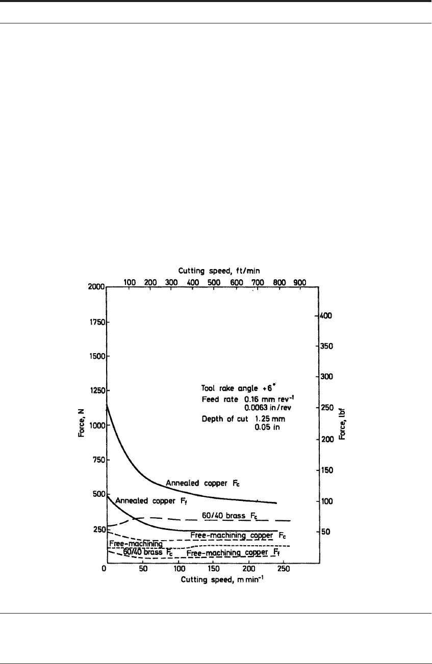
The addition of lead greatly reduces tool forces (Figure 9.8), which become almost indepen-
dent of cutting speed. No definite flow-zone is formed on the rake face of the tool. The absence
of a flow-zone, the greatly reduced strain in chip formation, and the segmented chips which
result from the addition of lead, can be seen by comparing Figures 9.7a and 9.7b. With the seg-
mented chips the contact area on the tool rake face is reduced. Lower ductility of the brass, as a
result of lead addition, may be partly responsible for the segmentation of the chips in the primary
zone. However, the main reason for the reduction in tool forces is the action of lead at the tool/
work interface.
FIGURE 9.8 Tool forces vs cutting speed - free cutting copper and brass (From data of Williams, Smart
and Milner
1
)

264 MACHINABILITY
Seizure between the brass and the tool seems largely to be eliminated by the lead which is con-
centrated at the interface. Figure 9.9a shows the contact area on the rake face of a high speed
steel tool after a quick-stop during cutting a leaded brass at 180 m min
-1
(600 ft/min). A concen-
tration of lead can be seen, which had been molten during cutting and had wetted the steel tool.
Confirmation of this action comes from observations of monatomic layers of lead on the under
surface of leaded brass chips. In addition, there are thicker layers, in striations, in the cutting
direction.
5
Figure 9.9 also shows the results of Wolfenden and Wright
6
using the equations in Chapter 5.
These calculations confirm that the lead is molten at the end of the chip tool contact area. This
concentration of lead at the interface reduces the tool forces. It also facilitates chip fracture by
reducing the compressive stress acting on the shear plane. Molten lead accumulates at the inter-
face because it wets the steel tool, as shown by the small contact angle of the lead droplets on the
tool. This also demonstrates that the tool surface at the interface is freed from oxide and other
surface films by the action of the work material. Lead does not wet oxidized steel surfaces.
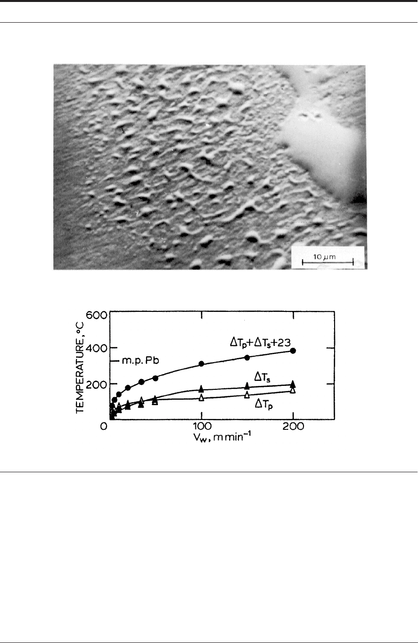
Another result of the action of lead is a large reduction in the energy of cutting both on the
shear plane and at the tool/work interface. This results in a considerable reduction of tool tem-
perature, Figure 9.6. The effect of lead addition to 60/40 brass is to reduce the tool temperatures
below those for high conductivity copper. The lower temperatures reduce tool wear. The main
advantages are the elimination of chip control problems and the reduction in tool forces.
9.4.4 Environmental concerns
Unfortunately for “machinability” alone, lead has become recognized as a serious health haz-
ard. Possible dangers arise both in melting and machining of leaded brass and also in the use of
leaded brass as fittings for water supply. With the possibility of regulations restricting the use of
leaded brass, producers now have to consider the machining of unleaded 60/40 brass on auto-
matic machines. Continuous brass chips can be broken into short lengths by forming grooves
parallel with the cutting edge on the rake face of tools. It has been shown that certain shapes of
groove are successful in breaking chips of unleaded 60/40 brass.
7
Additions are made also to high conductivity copper to improve its machinability. Additives
have to be confined to those which do not appreciably reduce electrical conductivity, or cause
fracture during hot working. About 0.3% sulfur is usually added. This forms plastic non-metallic
inclusions of Cu
2
S. The effect is to reduce greatly the tool forces, particularly at low speeds,
Figure 9.8. Also it produces thin chips which curl and fracture readily. The surface finish is
greatly improved. The action of Cu
2
S can probably be attributed to the reduction of seizure
between copper and the rake face. The sulfide particles are plastically deformed in chip forma-
tion, and very thin layers of sulfide are observed on the contact area after quick-stops. The flow-
zone, normally present after cutting high conductivity copper, is eliminated. The essential fea-
tures of Cu
2
S as a free-machining phase are: i) its plasticity during deformation in cutting, and
ii) its strong adhesion to the tool surface, which prevents it from being swept away. One result of
the sulfur addition is a large reduction in tool temperature up to very high cutting speed (Figure
9.6). The temperatures are even lower than those when cutting leaded brass.
COPPER, BRASS AND OTHER COPPER ALLOYS 265
FIGURE 9.9 a) Lead on rake contact area of high speed steel;
5
quick-stop after cutting leaded brass at
180 m min
-1
(b) calculations confirming melting of lead at end of contact zone
6
9.4.5 Gun metal
Wise and Samandi have investigated machining behavior of other copper-based alloys and
some of their findings are summarized next.
7,8
Gun metals are similar to zinc brasses but contain
a solution - for example, 5% Zn, 5% Sn, 1-5% Pb with the balance copper. They are normally
used as castings with lead added to improve machinability. Almost all criteria of machinability
are improved by lead. Cutting forces are low and are nearly constant over the whole cutting
speed range, particularly the feed force. Lead is concentrated at the interface and semi-continu-
ous chips are formed with periodic cracks through the chips. There is some continuity on the
under side but no flow-zone. Tool interface temperatures are low, e.g. 350°C at a speed of 140 m
266 MACHINABILITY
min
-1
(460 ft/min). At high cutting speeds, where the interfacial lead is melted during cutting,
the rate of wear is increased compared with that at lower speeds where the interfacial lead is
solid.
9.4.6 Aluminum bronze
Two aluminum bronzes have also been studied.
7,8
The first contained 10% Al, 5% Fe and 5%
Ni. The second, of improved machinability, contained 6% Al, 2% Si and 0.5% Fe. In both alloys,
the balance was copper. Both alloys are basically solid solutions of Al and Cu, but also contain
numerous fine precipitated particles containing Fe, Si and Al dispersed in the matrix. The two
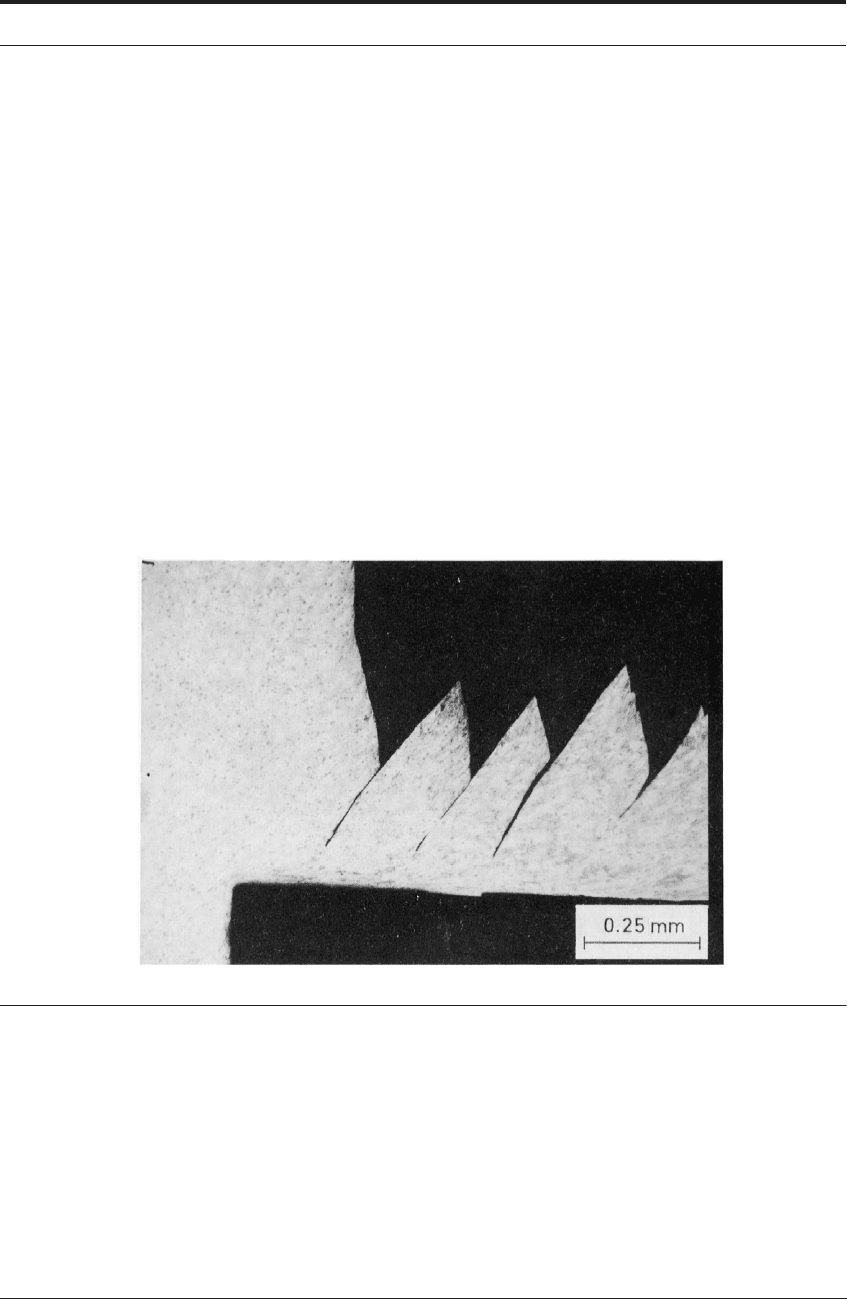
alloys showed similar machining behavior, very different from that of brasses. At low speeds, the
chips are completely segmented and discontinuous while at high speed they are segmented, but
the segments are joined together by a continuous flow-zone at the tool/work interface (Figure
9.10). Only slight plastic deformation takes place in the body of the chip before sudden fracture
occurs along the line of the shear plane. This leads to large fluctuations of cutting force. These
were synchronized with the periodic fracture, and a characteristic high noise level during cutting.
FIGURE 9.10 Quick-stop of aluminum bronze (10% Al); speed 75 m min
-1
(Courtesy of M. Samandi
8
)
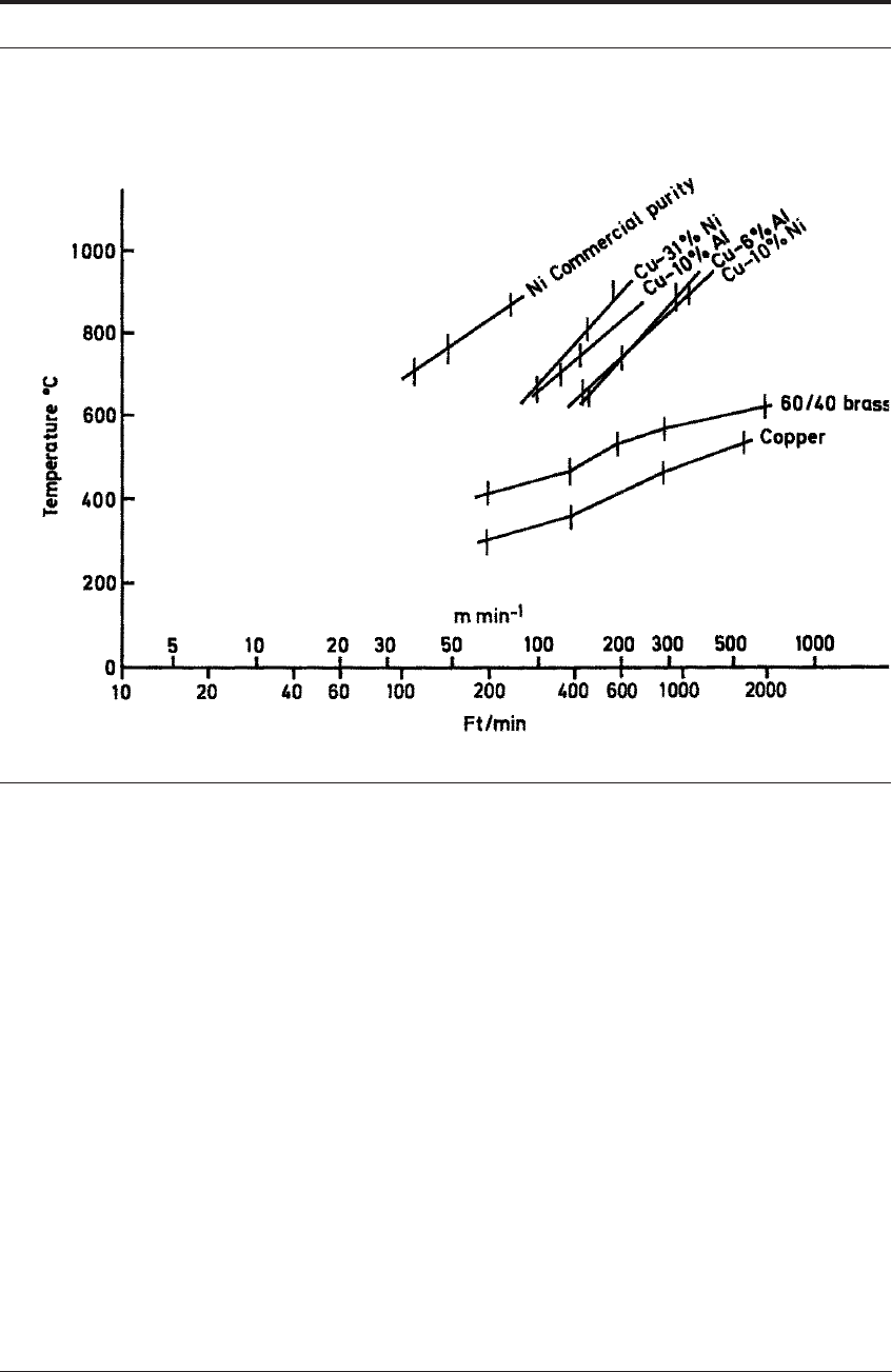
The cutting force and the feed force are both lower when cutting the 6% Al alloy. Because the
chip is segmented, the contact length on the tool rake face is very short and the maximum tem-
perature occurs less than 0.5 mm from the tool edge. The maximum temperature as a function of
cutting speed is shown in Figure 9.11. The 10% Al alloy generates much higher temperatures,
and the 6% Al alloy can be cut at much higher speeds for this reason. Aluminum bronze can be
machined with high speed steel tools, but cemented carbide (WC-Co alloys) can be used with
much longer tool life and at higher cutting speed.
COPPER, BRASS AND OTHER COPPER ALLOYS 267
FIGURE 9.11 Maximum interface temperature vs cutting speed
9.4.7 Cupro-nickel alloys
Cupro-nickels are highly ductile, single-phase alloys forming a continuous series of solid
solutions from copper (m.pt. 1,083°C.) to nickel (m.pt. 1,453°C.). The machining investigations
were carried out on two alloys with 10% and 31% nickel.
7,8
The behavior in machining is, in
many ways, the direct opposite to that of aluminum bronzes. Continuous chips are formed with
no segmentation over the whole cutting speed range. The work material is strongly bonded to
high speed steel or carbide tools over the whole contact area.
At low cutting speed, the cutting and feed forces were very high and the chips very thick with
a very small shear plane angle. As the cutting speed was raised chips became thinner and cutting
and feed forces dropped rapidly, as when cutting pure iron, nickel and copper. No built-up edge
was formed at low speed. At speeds of 25 m min
-1
and higher, a clearly defined flow-zone was
formed, where the maximum temperature was 500°C.
At higher speeds the temperature gradients were of a similar pattern as for iron and steel with
a maximum about 1.2 mm from the cutting edge (Figure 9.12). The maximum temperatures as a
function of cutting speed are shown in Figure 9.11 for the two cupro-nickel. These are higher
than for any other copper-based alloy. Temperatures for the 31% Ni alloy were much higher than
for the 10% Ni alloy at all speeds.
268 MACHINABILITY
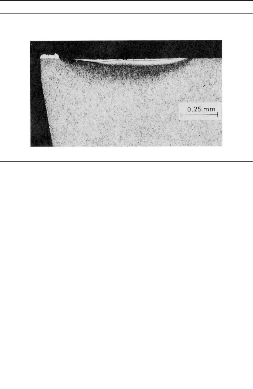
FIGURE 9.12 Section through high speed steel tool used to cut cupro-nickel (31% Ni) at 350 m min
-1
.
Etched to show temperature distribution
Flank wear occurred on high speed steel tools, and also cratering in the high temperature
region on the rake face. Rapid cratering occurred at a speed of 200 m min
-1
with the 31% Ni
alloy. It occurred at 350 m min
-1
with the 10% Ni alloy, when the interface temperature
exceeded about 900°C.
9.4.8 Summary on copper, brass and copper based alloys
The copper-based alloys considered here, demonstrate some of the ways in which alloying of a
ductile metal influences its machinability. When an alloying metal goes into solid solution in the
base metal - e.g. Zn or Ni in Cu - a strong continuous chip is formed. The most important factor
influencing machinability is that the temperature generated in the flow-zone is raised at any cut-
ting speed. This is because the alloying elements increase the energy expended in the work mate-
rial in the thermo-plastic shear zone at the tool/work interface. This increases the rate of tool
wear and limits cutting speed.
Lead is insoluble in solid copper and is present as dispersed particles. This influences the
behavior of alloys in metal cutting, because the lead becomes concentrated at the tool/work
interface. Also, it becomes strongly bonded to the steel tools. It provides a layer of very low
shear strength and greatly reduces energy expenditure. This further reduces tool temperatures,
permitting higher cutting speeds. It also causes segmentation of the chips, solving many chip
control problems. This action is seen both with free machining brass and with gun metal.
The machining behavior of the aluminum bronze alloys studied was very different from that of
the other copper alloys. Discontinuous chips were formed with very short contact length on the
tool surface. Thus, high temperatures were generated close to the cutting edge. Further research
is required to determine whether this behavior is caused by aluminum in solid solution, or
whether the dispersed particles of hard phases in these alloys caused the periodic fracture on the
shear plane.

COMMERCIALLY PURE IRON 269
9.5 COMMERCIALLY PURE IRON
Commercially pure iron, like commercially pure copper and aluminum, is in general a material
of poor machinability. At room temperature the structure is body-centred cubic (α iron), trans-
forming to face-centered cubic (γ iron) a just over 900°C. In both conditions, it has relatively low
shear strength but high ductility. The tool forces are much higher than for copper (Figure 4.12),
particularly at low cutting speed. However, the forces decrease rapidly as the speed is raised.
The high tool forces are associated with a large contact area on the rake face of the tool, and
thick chips. No built-up edge is observed at any speed, and quick-stops show a flow-zone about
25-50 μm (0.001-0.002 in) thick seized to the rake surface of the tool (Figures 3.14 and 5.4).
This is the main heat source raising the temperature of the tool.
Temperature distributions in cutting tools are discussed in Chapter 5. The problem is consid-
ered in relation to the cutting of a very low carbon steel, which is in effect a commercially pure
iron. Figures 5.10 to 5.18 demonstrate the temperature pattern characteristic of tools used to cut
this material. This pattern is very important in relation to the machinability of iron and of steel.
The upper limit of the rates of metal removal, using high speed steel and carbide tools, is deter-
mined by tool wear and deformation mechanisms controlled by these temperatures.
In general, this same type of temperature pattern occurs in tools used to cut carbon and alloy
steels, including austenitic stainless steels. A high temperature is generated on the rake face well
back from the cutting edge, leaving a low temperature region near the edge.
†
The temperature
increases as cutting speed and feed are raised.
9.6 STEELS: ALLOY STEELS AND HEAT-TREATMENTS
9.6.1 Overview
It is in the cutting of iron, steel and other high melting-point alloys that the problem of machin-
ability becomes of major importance in the economics of engineering production. With these
higher melting-point metals, the heat generated in cutting becomes a controlling factor. It
imposes constraints on the rate of metal removal and the tool performance, and hence on
machining costs. This main section reviews low-carbon, medium-carbon and general steels of
various heat treatment. “Free cutting steels” and stainless steels warrant main sections of their
own (Sections 9.7 and 9.8).
9.6.2 Influence of alloying elements on the forces and stresses on the tool
Alloying elements in steel (carbon, manganese, chromium, etc.) increase its strength. This
influences both the stresses acting on the tool and the temperatures generated. As with copper
†. It will be seen later that titanium alloys machine in such a way that the maximum temperature is much closer to the
cutting edge. Indeed the delicate cutting edge is, relatively speaking, much hotter than when machining steels. This
difference in temperature pattern is the major difference between iron/steel on the one hand, and titanium/titanium
alloys on the other.

270 MACHINABILITY
and aluminum, the effect of alloying additions to iron is often to reduce the tool forces as com-
pared with pure iron (Figure 4.13). However, the stress required to shear the metal on the shear
plane to form the chip is greater. And when cutting steel, as opposed to iron, the chip is thinner,
the shear plane angle is larger and the area of the shear plane is much smaller.
It is clear that the cutting force is reduced by the addition of alloying elements. However, the
created contact area is much less. Hence, the average compressive stress on the tool is always
higher by adding the alloying elements. How the average stress correlates with the maximum on
the delicate cutting edge has been investigated. The evidence reviewed in Chapter 4 demon-
strates that stress is at a maximum near the edge, generally 1.5 to 2 times the average value that
might be measured by a dynamometer. Numerical values of this stress when cutting steel, and
how it is affected by alloying additions, have been determined for the very limited number of
cases shown in Tables 4.7 and 4.8. More comprehensive testing and analysis are desirable.
The yield stress of steels is influenced by both composition and heat treatment. When steels
are heat treated to high strength and hardness, the compressive stress which they impose on tools
during cutting may become high enough to deform the cutting edge (Figure 6.15) and destroy
the tool. When using high speed tools, the machining of steels with hardness higher than 300 HV
becomes very difficult; even at low speeds where the tool is not greatly weakened by heat.
Cemented carbide tools can be used to cut steels with higher hardness. Even here, tool life
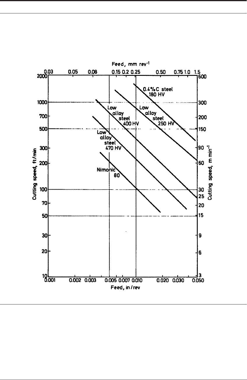
becomes very short and permissible cutting speeds very low when the hardness exceeds 500 HV.
Figure 9.13 shows the speeds and feeds at which carbide tools were found to deform severely
when cutting steels of different hardness.
9
For cutting fully hardened steel, the tool materials must retain their yield strength to higher
temperatures. Ceramic tools can be used to machine steel hardened to 600 to 650 HV. Higher
rates of metal removal and longer tool life can be achieved with cubic boron nitride tools on
fully-hardened tool steel (see Chapter 8). Because they are less tough than cemented carbides,
the range of operations on which they can be used is restricted. Additionally, tool costs are very
high.
9.6.3 Relative machinability of steel
A very high percentage of all cutting operations on steel is carried out using high speed steel
or cemented carbide tools. Guidance for selecting the optimum speed and feed for a particular
cutting operation involves many factors. Nominal cutting speeds and feeds for machining differ-
ent steels are often proposed by tool manufacturers and in books and papers on metal cut-
ting.
10,11
Most commonly, these relate the nominal cutting speed to the hardness of the steel.
Table 9.1 gives typical recommended cutting speeds for single point turning operations. Such
recommendations can be only a starting point for trials in practical machining operations. How-
ever, Table 9.1 is included here to give some idea of the range of speeds used in machining car-
bon and low alloy steels of different strength and hardness.
STEELS: ALLOY STEELS AND HEAT-TREATMENTS 271
FIGURE 9.13 Conditions of deformation of cemented carbide tools when cutting steels of different
hardness
9
9.6.4 Combined influence of alloying, heat treatment, stress and temperature
To permit higher metal removal rates, steel work-materials are often heat treated to reduce the
hardness to a minimum. The heat treatment for medium or high carbon steel often consists of
annealing just below the transformation temperature (about 700°C). This “spheroidizes” the
cementite - the form in which it has least strengthening effect, Figure 9.14. For some operations

272 MACHINABILITY
a coarse pearlite structure is preferred. This structure is obtained by a full annealing treatment in
which the steel is slowly cooled from above the transformation temperature.
In the machining of low carbon steel containing a lot of pro-eutectoid ferrite, slow cooling
from the annealing temperature is essential. This ensures that the carbon is not present in solu-
tion in the ferrite, nor as very finely dispersed particles. The heat treatment is necessary to make
sure that the carbon is not redissolved with the natural heating of the cutting process - thereby
accidentally returning the steel to a more-difficult-to-machine state.
12
When machining low car-
bon steels with high speed steel tools, failure by deformation of the tool edge occurs at a much
lower speed if the heat treatment is incorrect. This is because carbon is available in the steel
workpiece to strengthen the ferrite and increase its rate of strain hardening.
13
Thus, the rate of metal removal when cutting steel alloys is strongly limited by the high stress
imposed on the tool edge. The yield stress of the steel work material, and its rate of strain hard-
ening, are the main factors in its machinability.
Of equal or greater importance however, is the influence of the alloying elements in the steel
work material on the temperatures and temperature gradients generated in the cutting tools.
These cannot at present be predicted from the mechanical properties because of the extreme con-
ditions of strain and strain rate in the flow-zone, which is the heat source. This is discussed in
Chapter 5.
TABLE 9.1 Typical maximum turning speeds for steel
Hardness High speed steel tools Cemented carbide tools
Feed, 0.5 mm/
rev
Feed, 0.25 mm/
rev
Feed, 0.5 mm/
rev
Feed,0.25 mm/
rev
(HV) (Rockwell)
(m min
-1
)
(ft/min) (m min
-1
) (ft/min)
(m min
-1
) (ft/min) (m min
-1
) (ft/min)
90-125 48-69 RB 40 130 55 180 180 600 205 680
125-160 69-82 RB 34 110 46 150 155 510 180 690
160-210 82-93 RB 27 90 35 115 130 420 160 530
210-250 13-22 RC 21 70 30 100 115 380 140 460
250-300 22-30 RC 18 60 24 80 100 330 130 420
300-350 30-35 RC 15 50 18 60 85 280 115 370
350-400 35-41 RC 70 230 85 280
400-450 41-45 RC 45 150 60 200
450-500 45-49 RC 35 120 45 150