Trent E.M., Wright P.K. Metal Cutting
Подождите немного. Документ загружается.

PERFORMANCE OF LAMINATED AND COATED TOOLS 213
layers. The coefficient of thermal expansion of the coatings is generally higher than that of the
substrate. Cooling from the coating temperature therefore introduces tensile stresses into the
layers and polishing of coating surfaces generally reveals a network of very fine cracks. These
penetrate no deeper than the coating, but transverse rupture tests show a drop in strength com-
pared with un-coated carbide.
27
There is no evidence that this influences the performance of
clamped-tip tools, the main type of tooling for which coated tools are used.
7.9.3 Performance of coated tools
A large proportion of indexable inserts for cutting iron and steel is now coated. The success
of coatings is based on their proven ability to extend tool life by a factor of 2 or 3 by reducing
the rate of wear in high speed turning of cast iron and steel. Many users consider that more
important economies are made by increasing cutting speed by 25 to 50% without reduction in
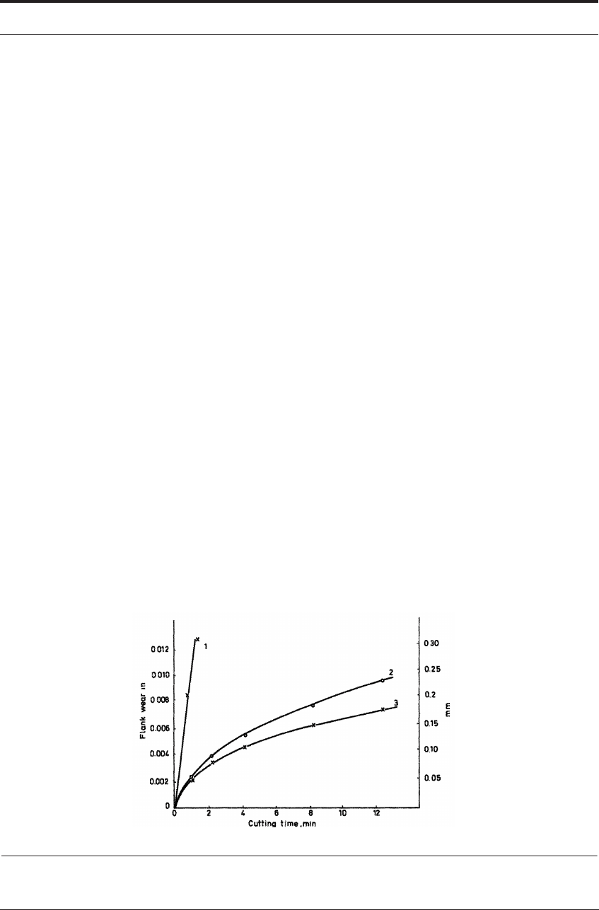
tool life. Figure 7.34 is a typical set of laboratory test results comparing the rate of flank wear
on coated and uncoated carbide tools. Coated tools cannot be universally applied even in turn-
ing; operations involving severe interruptions of cut may fracture and flake away the coatings.
Improvement in the bonding has made them more suitable for milling operations.
27-30
Research has indicated that the wear resistant qualities of TiC, TiN and alumina coatings are
mainly because of their high resistance to diffusion wear on the parts of the tool surface where
seizure occurs.
15
Evidence from quick-stops demonstrates that the coatings do not prevent sei-
zure when cutting steel at high speed
31
(though they may eliminate the built-up edge at low
speed). The heat source raising the tool temperature is still a flow-zone and the temperatures
appear to be only slightly lower with coated than with uncoated tools. For this reason the rate of
metal removal, particularly when cutting high strength materials, is limited by the ability of the
substrate to withstand the stress and temperature at the cutting edge. These very thin coatings on
cemented carbide substrates may be worn-through locally at the positions of most rapid wear,
such as the center of the crater or on the flank just below the edge, but the coating will continue
to be effective in reducing the rate of wear as long as it remains intact at the cutting edge.
15,28
FIGURE 7.34 Tool wear vs time for coated and uncoated cemented carbide tool tips. (1) Uncoated steel
cutting grade; (2) coated WC-Co alloy and (3) coated steel cutting grade

214 CUTTING TOOL MATERIALS II: CEMENTED CARBIDES
7.9.4 Comparisons between different types of coating
There are differences between the different coatings in respect of their resistance to flank and
crater wear. Most reported results on steel cutting suggest that TiN is more resistant than TiC to
crater wear and that TiC is more resistant to flank wear. The crater and flank wear rates of alu-
mina-coated tools appear to be not greatly different from those of carbide and nitride coated
tools. There is evidence that the crater wear of alumina coatings is caused by superficial plastic
deformation, rather than by a diffusion mechanism.
15
The greatest difference in wear rate is
reported to be that in the notch at the outer edge of the chip (Figures 6.23 and 6.24) where slid-
ing rather than seizure occurs. Wear at this position was minimal with alumina coatings. TiN
coatings were nearly as good as alumina, but notch wear on TiC coatings was very much greater
and not greatly different from that on uncoated tools.
7.9.5 Multiple layer and nanolayer coatings: a design goal
It is clear that there is a place for more than one type of coating, and therefore multi-layer
coatings may provide a type of tool which will cope well with a variety of operations. Colloqui-
ally speaking, could research work discover a tooling combination that would “give the best of
all worlds”? It might consist of a tough carbide core - probably one of the WC-Co, “K-grades” -
coated with several layers: one that would bond reliably to the core; another that would buffer
thermal-expansion discrepancies; another that would provide insulation; another that would
buffer diffusion wear; another on the very outside that would have ultra-low friction characteris-
tics.
Will such an “all-purpose”, multi-layer “sandwich” eventually be discovered over the next
few years? This is the new challenge to cutting tool developers. Some progress is reviewed in
the next two sections.
7.9.6 Multiple layer coatings
For such multiple-layer “sandwiches” the first layer is usually TiN or TiCN created by the
PVD process. These can be created on straight WC-Co substrates, or on mixed carbide sub-
strates of varying cobalt content. TiN or TiCN minimize or eliminate the formation of -phase
(Co
x
W
y
C
z
) at the interface with the substrate. It is also common to create the last, or outer, layer
of the “sandwich” with TiN using PVD. This induces beneficial residual compressive stresses on
the complete structure.
In today’s industrial inserts of this type, multiple layers of only TiN may in fact be successful.
Multiple layering allows the final thickness of the “sandwich” to be as much as 10-15 m. This
is greater than can be achieved by trying to create the whole layer in one operation. When used
in turning and milling operations, the successive layers of very thin coats, rather than one heavy
coat, give a more stable structure. In other, triple-layer “sandwiches” the middle layer is often
TiCN as shown earlier in Figure 7.33.
Beyond this, Komanduri
32
reports that many “sandwich” combinations are being investigated
today including the following: {TiN-Al
2
0
3
-TiC-TiCN}, or {TiN-TiCN-TiC}, or {TiN-A1
2
0
3
-
TiCN}, or {A1
2
0
3
-TiC}, or {A1
2
0
3
-TiC-TiCN}, or {TiN-A1
2
0
3
-TiC}, or {TiN-A1
2
0
3
-TiN-
A1
2
0
3
-TiN-A1
2
0
3
-TiCN}. In addition, Komanduri reports that one grade of TiN-A1
2
0
3
on a
η
μ

PRACTICAL TECHNIQUES OF USING CEMENTED CARBIDES FOR CUTTING 215
Si
3
N
4
substrate is also available, but that the technology to coat crystalline A1
2
0
3
by PVD is not
feasible today.
7.9.7 Multiple nanolayer coatings
Nanotechnology also involves sputtering, i.e. deposition, by PVD. It is being used today in a
wide variety of industries. These include CMOS semiconductor wafer manufacturing, and the
manufacture of the wafers that become the read-write heads for computer disc drives. Magne-
tron sputtering with many types of targets can be employed and the wafers are rotated with
respect to the target. The sputtering rate and the rotational speed of the turntable that holds the
wafers, determine the thickness of the coated layer.
Such coating technologies are also being investigated for cutting tools because unusual com-
binations of layers can be built up. The key concept is to deliberately mix alternating hard and
tough layers. Shaw
33
and colleagues report that a crack that might be initiated in a hard, brittle
layer is arrested when it meets the tough layer thereby increasing the overall fracture toughness
of the whole ensemble. Almost any refractory hard material can be used as the hard nanolayer;
almost any compatible metal can be used as the tough nanolayer. An example of the {hard car-
bide + metal} nanolayered system might be {B
4
C + W}. Or perhaps the B
4
C might be replaced
by {HfC, SiC} and the W by {Al, Cr, Ti, Si, Mg, Zr}.Oxidation resistant layers and low-friction
layers of molybdenum disulphide (MoS
2
) can also be mixed in. When using introducing nano-
layers of MoS
2
, the adjacent, non-MoS
2
nanolayers interrupt the formation of columnar grains
of MoS
2
which are ineffective as lubricants. This interruption produces a uniform equiaxed
structure of MoS
2
throughout the coating, which are very effective as lubricants.
Whereas each layer of the multiple-layer “sandwich” may only be a few nanometers thick,
the total thickness can be in the range of 2-5 m. Komanduri
32
reports that while today, nano-
coatings for cutting tool applications are not being used commercially, the number of potential
combinations of material systems that can be used for nanolayer coatings is virtually unlimited.
Thus the technology is expected to grow in the future.
32-34
7.10 PRACTICAL TECHNIQUES OF USING CEMENTED
CARBIDES FOR CUTTING
7.10.1 Early methods using brazed-on carbide tips
High speed steel tools are normally made in one piece, but from their earliest days cemented
carbides were made in the form of tool tips: small inserts which were brazed into a seat formed
in a steel shank. Except for very small tools, it was not economical to make the whole tool of
cemented carbide (which typically costs 20 times as much as high speed steel, weight for
weight) and there was normally no advantage in terms of performance. A brazed carbide was
used until worn and was then reground. Most grinding of carbide tools required the use of
bonded diamond grinding wheels, and more skill was required and the cost was greater than for
grinding high speed steel tools.
μ
216 CUTTING TOOL MATERIALS II: CEMENTED CARBIDES
7.10.2 The transition to throw-away tool tips or indexable inserts
Because cemented carbides are less tough than high speed steel, the tool edge must be more
robust. With steel tools the rake angle may be as high as 30°, so that the tool is a wedge with an
included angle as small as 50° (Figure 2.2). The rake angle of carbide tools is seldom greater
than + 10° and is often negative (Figure 2.2). A tool with an included angle of 90° set at a nega-
tive rake angle of - 5° is particularly useful for conditions of severe interruption of cut, or when
machining castings or forgings with rough surfaces.
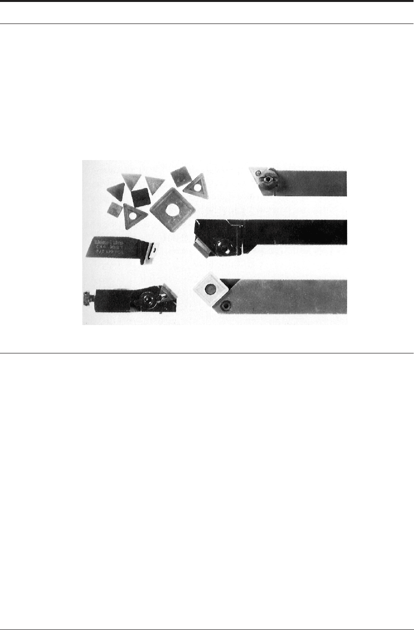
FIGURE 7.35 Indexable insert tool tips of cemented carbide
This common usage of tools with low positive rake, or negative rake angles led to the concept
of throw-away tool tips. These are small ‘tablets’ of carbide, which are usually square or triangu-
lar in plan, though other shapes may be used (Figure 7.36). Each tip has a number of cutting
edges. Positive rake, triangular tips have three cutting edges. Negative rake square tips have
eight cutting edges.
In use, the tips are mechanically clamped to the tool shank using one of a number of different
methods. When a cutting edge is worn, and the tool no longer cuts efficiently, the tip is
unclamped and rotated to an unused corner, and this is repeated until all the cutting edges are
worn. Then, the tip is discarded rather than reground. Used in this way, the tips are called index-
able inserts. Very little of the tool material is worn off when the tool tip is thrown away, but, in
spite of this, in many operations very considerable economies are achieved compared with the
possible use of a brazed tool which would have to be reground. The high cost of regrinding is
eliminated, the time required to change the tool is greatly reduced, and the cost of brazing is
avoided.
The powder metallurgy process is well adapted to mass production of carbide tool tips. These
are made by pressing on automatic presses, followed by a sintering operation, which produces
tips of high dimensional accuracy, so that little grinding is required. The introduction of throw-
away tooling has made possible important new lines of development in tool shapes and materi-
als. The tool edges can be given considerable protection against chipping caused by mechanical
PRACTICAL TECHNIQUES OF USING CEMENTED CARBIDES FOR CUTTING 217
impact, by slightly rounding the sharpened edge. Many manufacturers supply edge-honed tips,
on the cutting edges of which there is a small radius, usually about 25 to 50 μm (0.001-0.002
in). Such tips can give much more consistent performance in many applications, without the rate
of wear being increased.
Tips are also made with grooves formed in the rake face close to the edge which curl the
chips into shapes which can be readily cleared from around the tool. Clearance of chips from the
cutting area is of increasing importance for efficiency of machining operations on automated
CNC machine tools. The ability to cut for long periods without stopping to clear chips can have
a large effect on machining costs. Carbide tool manufacturers have put great effort into design-
ing chip grooves of optimum shape for operation in wide ranges of speed, feed, depth of cut and
work material. A large number of patents cover these edge shapes. The research of Jawahir and
colleagues
35
is also of particular interest in this regard.
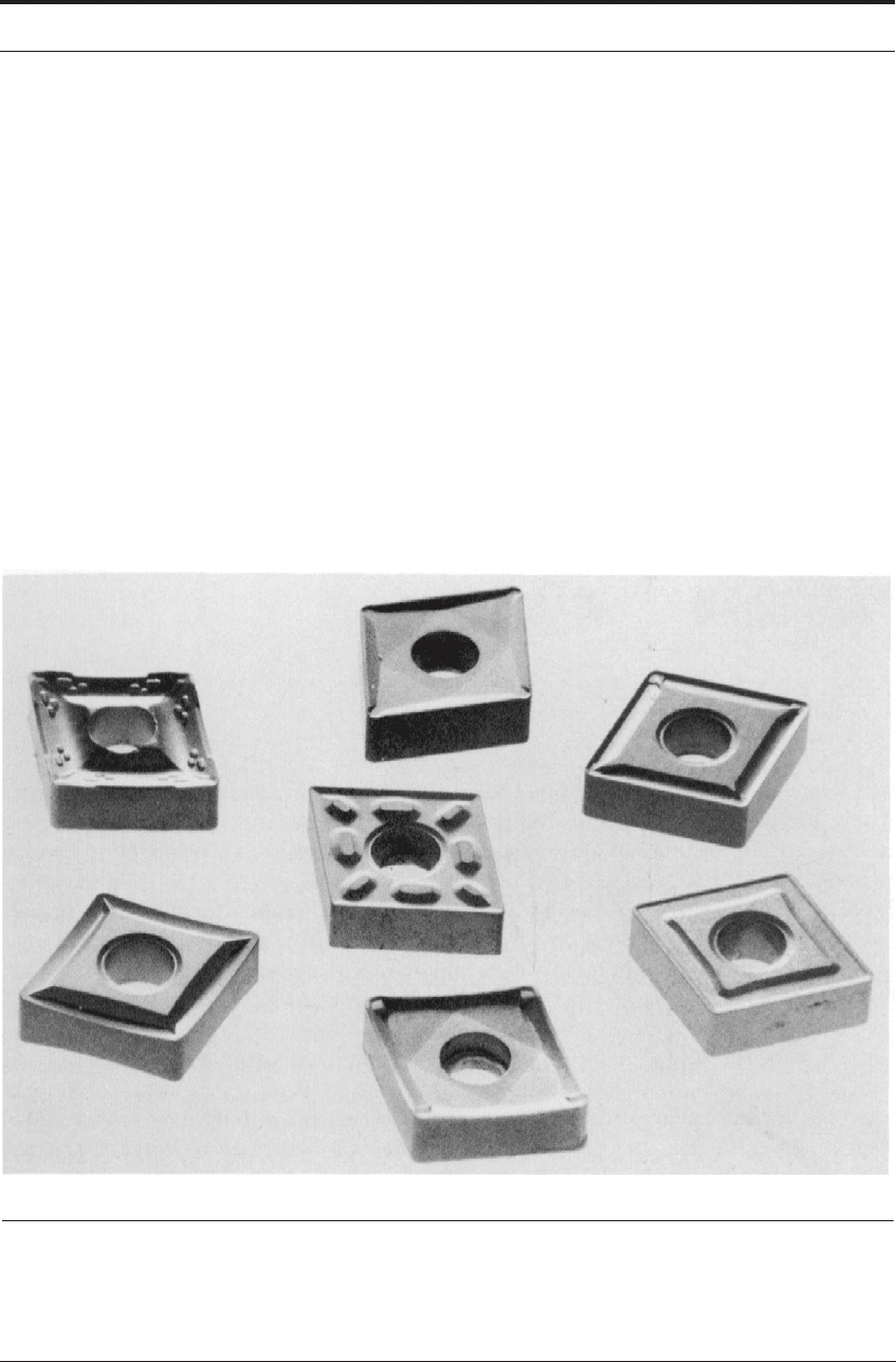
Figure 7.36 shows chip grooves on indexable inserts marketed by one carbide tool producer
to meet requirements for chip control when cutting specific work materials at different speed,
feed and depth of cut.
FIGURE 7.36 Chip groove shapes on indexable inserts produced by one carbide tool manufacturer.
(Courtesy of Kennametal Inc.)
218 CUTTING TOOL MATERIALS II: CEMENTED CARBIDES
Chip-form Classification
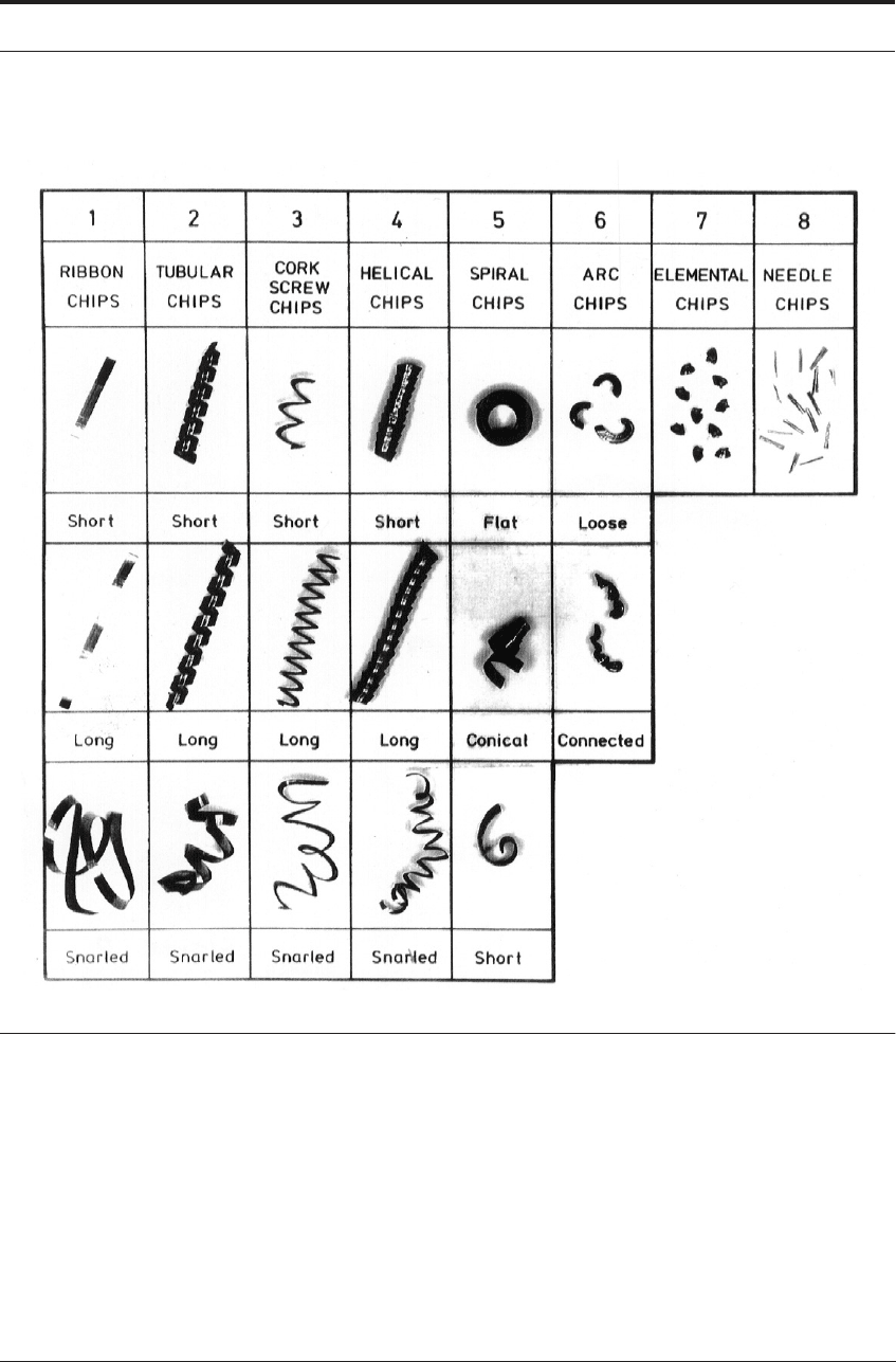
FIGURE 7.37 ISO-based chip-form classification (Figures 7.37 to 7.42 are reproduced with the
permission of Professor I.S. Jawahir)
Figure 7.37 shows the most commonly known ISO-based chip-form classification.
36
Figure
7.38 shows a typical chip chart showing the different regimes of chip formation for various feeds
and depths of cut. The representation of chip-forms as a chip-chart enables immediate visual rec-
ognition of acceptable and unacceptable regimes of chip formation. The chip chart, thus, not
only provides the performance capability of a grooved cutting tool, but also serves as an impor-
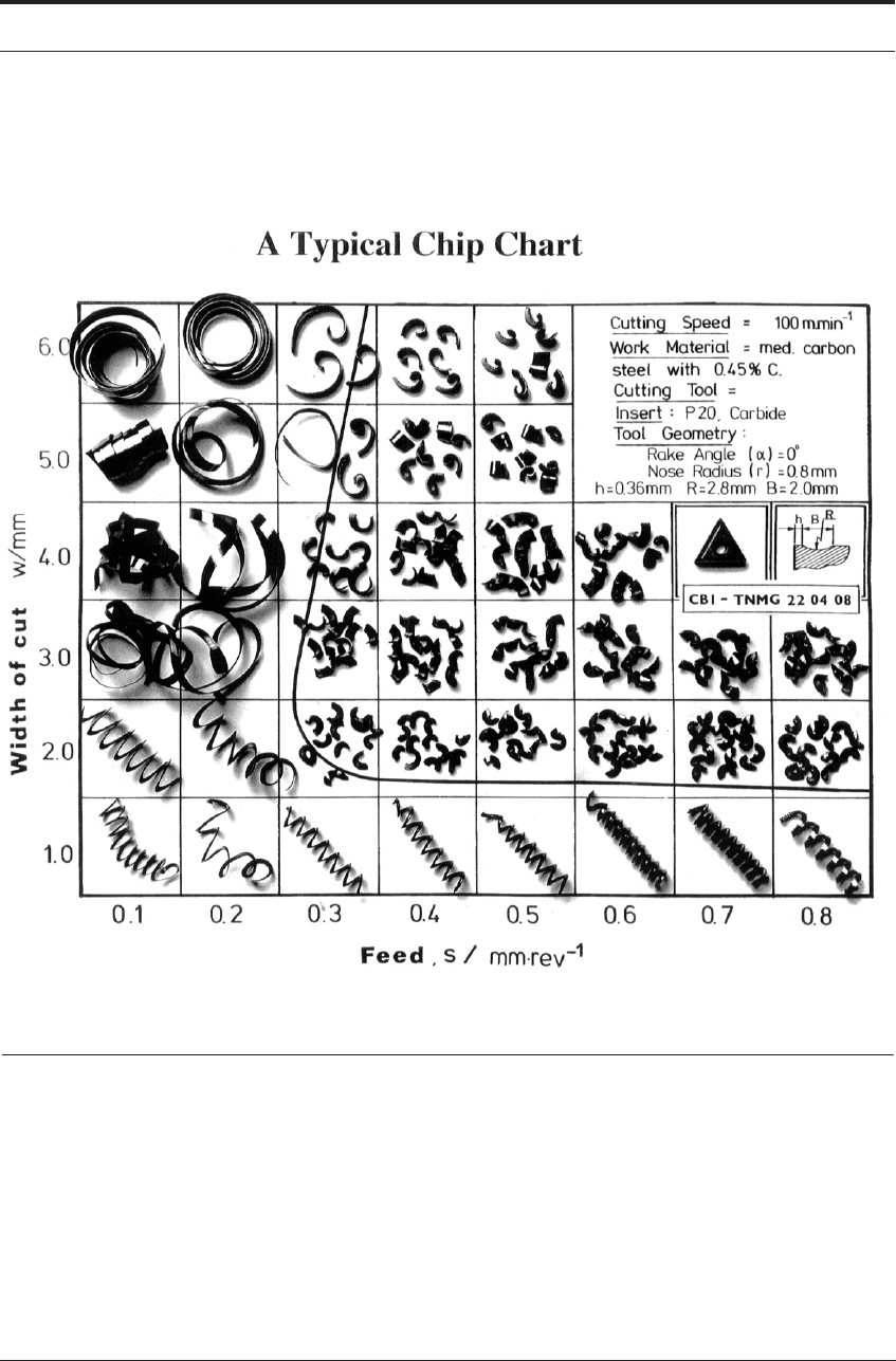
PRACTICAL TECHNIQUES OF USING CEMENTED CARBIDES FOR CUTTING 219
tant tool in selecting cutting parameters (such as feed, depth of cut, cutting speed) for a particu-
lar operation.
FIGURE 7.38 A representative chip chart showing the regimes of chip formation for varying feeds and
depths of cut (Cutting speed = 100 m min
-1
, rake angle = 0 deg., nose radius = 0.8 mm, work material =
1045 steel)
One of the significant results from the research on chip-forms and chip breakability
37,38
has
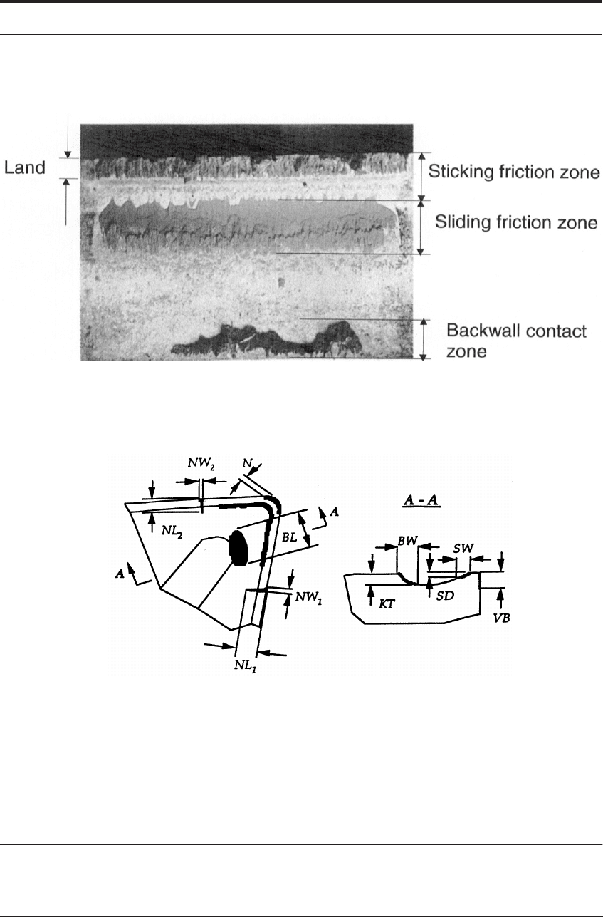
been the establishment of chip breaking as a cyclic process. Recent work has shown the effect of
the cutting tool thermal conductivity on the tool-chip contact length and the chip-form in
orthogonal cutting with a grooved tool. Regions of sticking friction, sliding friction and the con-
tact at the groove backwall have been identified (Figure 7.39).
220 CUTTING TOOL MATERIALS II: CEMENTED CARBIDES
FIGURE 7.39 Tool-chip contact zones in machining with a grooved tool (Cutting speed = 100 m min
-1
,
feed = 0.3 mm/rev., work material = 1045 steel)
VB flank wear N nose wear
BW width of groove backwall wear NL
1
notch wear length on main cutting edge
BL length of groove backwall wear NW
1
notch wear width on main cutting edge
KT depth of groove backwall wear NL
2
notch wear length on secondary cutting edge
SW width of secondary face wear NW
2
notch wear width on secondary cutting edge
SD depth of secondary face wear
FIGURE 7.40 Measurable tool-wear parameters in a grooved tool
PRACTICAL TECHNIQUES OF USING CEMENTED CARBIDES FOR CUTTING 221
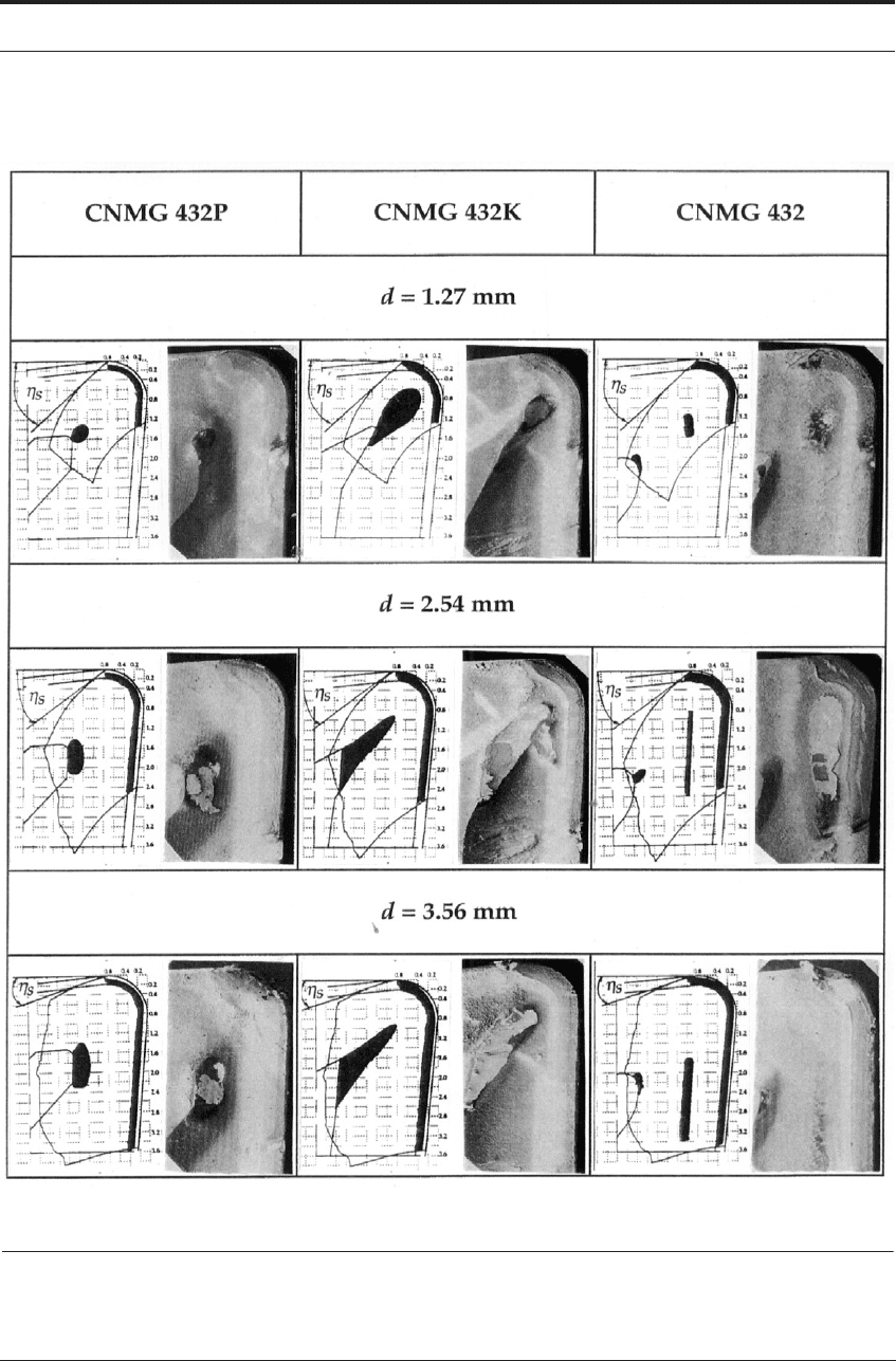
FIGURE 7.41 Variation of tool-wear patterns in three chip-grooves at varying depths of cut (cutting speed
= 274 m min
-1
, feed = 0.25 mm/rev., work material = 1037M steel)

222 CUTTING TOOL MATERIALS II: CEMENTED CARBIDES
The measurable tool-wear parameters
39,40
for a typical grooved tool are shown in Figure
7.40. Section A-A in the figure represents the approximate chip-flow direction for a given set of
cutting conditions. The influence of the chip-groove geometry can be understood from its effect
on the 3-D chip flow on the tool rakeface. The variations in cutting conditions (feed, depth of
cut, cutting speed) and the tool geometry (inclination angle, rake angle, nose radius, side-cutting
edge angle) also significantly affect the 3-D chip flow, and consequently the tool-wear parame-
ters. In many instances, the grooved tool fails due to unfavorable chip flow resulting from either
improper chip-groove design or inappropriate application of cutting conditions. Figure 7.41
shows the variation of the wear regions with depth of cut for three different grooved tool inserts.
Tool-life
41
varies significantly when using different chip-grooves and coatings. A new tool-
life relationship incorporating these two effects has recently been developed. This improved new
tool-life relationship is summarized as follows:
(7.1)
where V = cutting speed; T = tool-life; n = Taylor's tool-life exponent; T
R
= reference tool-life,
V
R
= reference cutting speed, W
c
= coating effect factor and W
g
= chip-groove effect factor.
(7.2)
where n
c
is the actual tool-life slope modified by the coating effect.
(7.3)
where f = feed; d = depth of cut; m = machining operation effect factor; n
1
, n
2
and k = empirical
constants. Figures 7.42a and b show the tool-life variations with feed and depth of cut respec-
tively for four different grooved tool inserts.
TT
R
W
g
V
R
V
------
⎝⎠
⎛⎞
W
C
1
n
---
=
W
C
n
n
c
-----=
W
g
km
f
n
1
a
n
2
-----------------=