Swaminathan N., Bray K.N.C. (eds.) Turbulent Premixed Flames
Подождите немного. Документ загружается.

3.2 Control Strategies for Combustion Instabilities 193
controller
filter
microphone
loudspeaker
flame stabilised
on grid
white noise
+
+
controller
K(s)
Rijke tube
loudspeaker
open-loop system, G(s)
microphone
+ filter
+
−
c
loudspeaker
input to
V
microphone/filter
output from
p
ref
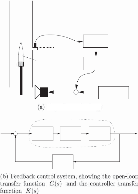
Experimental setup
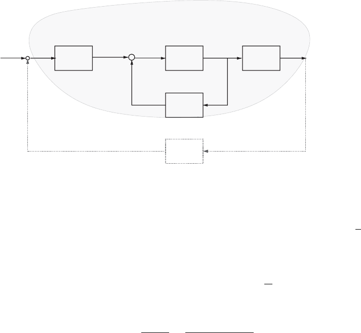
Figure 3.30. The Rijke tube exhibiting
a combustion instability.
MEASURING THE OPEN-LOOP TRANSFER FUNCTION (OLTF). The transfer function ap-
proach to controller design, also known as classical control theory, is used in con-
troller design. For an overview of this refer to [135, 136]
The OLTF needed for control purposes is from the actuator signal to the sensor
signal, in this case from t he loudspeaker voltage V
c
to the filtered microphone reading
p
ref
. This is shown as G(s)inFig.3.30(b), where s denotes the Laplace transform
variable. As with all naturally unstable systems, characterising G(s) is complicated by
the fact that, during instability, nonlinear limit cycle behaviour dominates and masks
the linear relationship that would be observed at low oscillation amplitudes. To
prevent the growth of small perturbations, it is measurement of the linear behaviour
that is required for controller design.
To overcome this problem, a loudspeaker voltage input V
c
is used, which com-
prises two components:
1. a control signal from a trial-and-error controller to eliminate the nonlinear limit
cycle, and
2. a wide bandwidth signal, in this case white-noise signal from a white-noise
generator, for identification of the OLTF.
One may ask this question: If a trial-and-error controller has been found, why do
we need to design another controller? The answer lies in the superior performance
194 Combustion Instabilities
2000 4000 6000 8000 10000
−50
−40
−30
−20
−10
0
Gain in dB
2000 4000 6000 8000 10000
−720
−360
0
−540
−180
Phase in deg
ω in rad/s
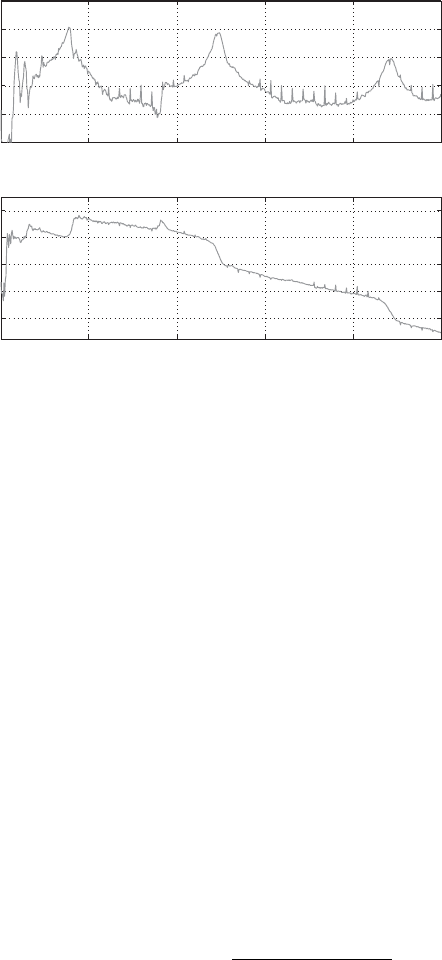
Figure 3.31. The measured Bode diagram of G(s) = p
ref
(s)/V
c
(s) for the Rijke tube.
of a model-based controller: Feedback control is most successful when an accurate
model of the system to be controlled is available.
Measuring the OLTF involves applying the preceding voltage input to the loud-
speaker, recording the r esponse of the filtered microphone signal, and using the
ratio of Fourier transforms to deduce the open-loop frequency response G(iω). Note
that it is important to use the total loudspeaker voltage in deducing this, not just
the white-noise component. Although the controller causes the loudspeaker input
spectrum to have a peak at the unstable frequency, applying sufficiently loud white
noise ensures that this peak does not dominate.
The open-loop frequency response G(iω) is shown as the Bode diagram of G(s)
in Fig. 3.31. The magnitude peaks represent system resonances and correspond to
the various ‘organ-pipe’ modes of the acoustic waves in an open-ended tube. For
example, the fundamental frequency of an open–open tube has a wavelength of
twice the tube length, in this case 1.5 m. The fundamental frequency is then c/(2L),
where
ˆ
c is the speed of sound in the tube. Taking this to be 360 m/s gives a fundamental
frequency of 240 Hz or approximately 1500 rad/s, which is the frequency of the first
modal peak.
By considering each modal peak to be caused by a second-order transfer func-
tion,
A
(s
2
+ 2ζ
n
ω
n
s + ω
2
n
)
,
stability information can be deduced from the phase change across the modal peaks.
A phase increase of 180
◦
indicates an unstable conjugate pair of poles (ζ
n
< 0)
whereas a phase decrease of 180
◦
indicates a stable conjugate pair (ζ
n
> 0). The
measured transfer function shows that the first (fundamental) mode is unstable,
whereas all other modes are stable.
CONTROLLER DESIGN. The system is single-input–single-output, and so Nyquist tech-
niques [135, 136] provide a suitable means of designing robust controllers. The exper-
imentally characterised G(iω) can then be used directly in controller design: Subject
3.2 Control Strategies for Combustion Instabilities 195
−0.4 −0.3 −0.2 −0.1 0 0.1 0.2 0.3
−0.25
−0.2
−0.15
−0.1
−0.05
0
0.05
0.1
0.15
0.2
0.25
Real part
Imaginary part
(a) G (iω)
−2 −1.5 −1 −0.5 0 0.5 1
−1
−0.8
−0.6
−0.4
−0.2
0
0.2
0.4
0.6
0.8
1
Real part
Imaginary part
+
−1
(b) G(iω)K(iω)
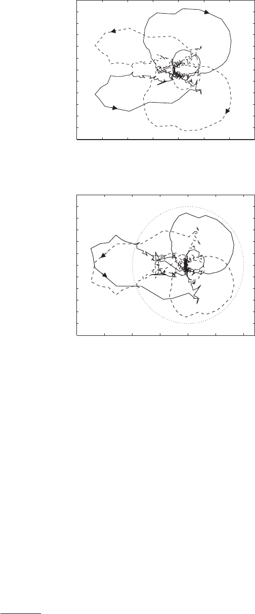
Figure 3.32. Nyquist diagrams: positive ω,---
negative ω.
to the system having low noise, there is no need to model or approximate what has
been measured. The Nyquist diagram for G(s)isshowninFig.3.32(a). According to
the Nyquist criterion, a negative feedback system such as that in Fig. 3.30 is stable if
the number of anticlockwise encirclements of the −1 point shown by the controlled
OLTF, G(s)K(s), is equal to the number of unstable poles in the uncontrolled OLTF,
G(s)[135, 136]. The phase increase across the first mode confirms that this is the
only unstable mode and that it has a pair of unstable poles associated with it. The
Nyquist plot for G(s)K(s) therefore needs to encircle the −1 point in an anticlock-
wise direction twice in order for the closed-loop system to be stable. The Nyquist
plot for G(s) has no encirclements of the −1 point. To achieve two encirclements, it
is clear that the controller should introduce both gain and additional phase lag near
the frequency of the unstable mode.
A good choice of controller structure to achieve this is that of a phase-lag
compensator:
K(s) =
k(s + βa)
(s + a)
, where β ≥ 1. (3.61)

196 Combustion Instabilities
The maximum lag should be close to the location of the unstable mode, which from
the Bode plot in Fig. 3.31 is at a frequency of ω = 1600 rad/s. The maximum lag of
the phase-lag compensator in Eq. (3.61) occurs at an approximate frequency of a
√
β,
and so good choices of values for the controller are a = 980, β = 2.67. These values
give a good compromise between maximising the phase and gain margins. The value
of k is then chosen to be 3.1 to maximise the gain margin (note that the gain–phase
margins must be considered in terms of both reducing and increasing the gain or
phase because two encirclements of the −1 point are required).
The resulting Nyquist plot for G(s)K(s) is shown in Fig. 3.32(b). It can be seen
that there are indeed two anticlockwise encirclements of the −1 point. The gain
margin is 4.5 dB and the phase margin is 21
◦
; thus the closed-loop system should
be stable and reasonably robust to plant uncertainties and changes (if needed, the
stability margins could be increased by use of a higher-order controller).
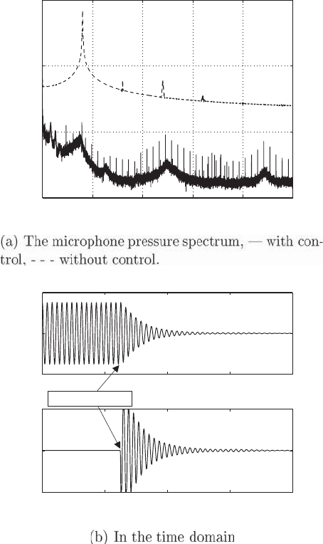
CONTROLLER IMPLEMENTATION. After the preceding controller is implemented on
the Rijke tube, it is seen to eliminate the combustion instability. The effects of
control on both the measured pressure spectrum and the time-domain oscillations are
shown Fig. 3.33. Control gives a reduction of approximately 80 dB in the microphone
pressure spectrum: This represents a reduction of four orders of magnitude. The
controller obtains control rapidly, with oscillation amplitudes down to 10% of their
unstable levels in fewer than 10 oscillations. Although the loudspeaker voltage is
initially large in order to attain control, once control has been achieved very little
actuator effort is needed to maintain it.
CONTROL STRATEGIES – ADAPTIVE CONTROL. The type of model-based controllers
considered so far are robust to small changes, but are essentially designed for a
single operating condition. Their redesign would be necessary should the operating
conditions change significantly. Adaptive controllers, whose parameters are contin-
ually updated to track plant changes, offer an efficient means of achieving control
across a range of operating conditions. Although some adaptive controllers, such
as neural networks, gain information about the plant offline [137, 138], others treat
the combustion system as a ‘black box’ and rely on an online system identifica-
tion. The first adaptive controllers to be applied to combustion oscillations were
least-mean-squares (LMS) controllers [139, 140]. These have the form of infinite-
impulse-response (IIR) filters whose coefficients are updated according to the LMS
algorithm [141]. Despite recent improvements to the online system identification
within the algorithm [142], LMS controllers are unlikely to be sufficiently robust for
use in practical applications as they rely on assumptions such as the primary noise
source being slowly varying and do not offer any guarantees of global stability.
Possibly the most physics-based type of adaptive control is guided directly by
the Rayleigh criterion [105, 143]. Open-loop testing is first used to determine the
time delay between the actuator input signal and the heat release rate as a function
of frequency. When control is activated, a real-time observer, similar to the one
described in Subsection 3.2.3, is used to detect and track the frequencies, amplitudes,
and phases of several combustor modes. This real-time detection combined with the
open-loop information then allows fuel to be added unsteadily such that the heat
release rate is exactly out of phase with the pressure fluctuations. Even though only
3.2 Control Strategies for Combustion Instabilities 197
0 2000 4000 6000 8000 10000
0
50
100
150
Sound pressure level in dB
Frequency in rad/s
4.3 4.35 4.4 4.45 4.5
−500
0
500
time in s
mic pressure in Pa
4.3 4.35 4.4 4.45 4.5
−5
0
5
time in s
loudspeaker voltage in V
control switched on
Figure 3.33. The effect of the model-
based controller on the Rijke tube
instability.
a gain–time-delay controller is used, the observer ensures that any secondary peaks
created are detected so that the control action can adapt to the new frequencies. This
approach has been demonstrated experimentally on a large-amplitude instability in
a small-scale gas rocket motor, in which the observer detected the most dominant
mode, and has since been extended to a full-scale gas turbine combustor [144].
A particularly attractive approach to adaptive control, which avoids the need
for either detailed prior measurements or online system identification, is to use self-
tuning regulators (STRs). The remainder of this subsection discusses the use of STRs
as adaptive controllers.
STR ADAPTIVE CONTROL THEORY. STRs are model-based adaptive controllers [145].
They use some general properties of the open-loop system to infer the controller
structure needed for stability and then update the controller parameters by using
a Lyapunov-based algorithm. A brief outline of STR background theory is now
provided.

198 Combustion Instabilities
For the class of combustion systems whose OLTF has relative degree
3
n
∗
equal
to 1 or 0, it follows from root-locus arguments that a first-order compensator of the
form
K(s) = k
1
s + z
c
s + p
c
(3.62)
can always stabilise the system if its parameters are chosen correctly. The adaptive
control algorithm seeks to find stabilising values for the parameters of this first-order
compensator. Note that real combustion systems have infinite dimension because of
the presence of time delays. In practice, the requirement that n
∗
= 0 or 1 therefore
translates to the requirement that the OLTF is well approximated by a rational
transfer function with n
∗
= 0 or 1 over a sufficiently wide frequency range.
If we define W
∗
cl
(s) as the transfer function of the resulting closed-loop stabilised
system, the derivation of such an adaptive control algorithm relies on W
∗
cl
(s) being
strictly positive real (SPR). If W
∗
cl
(s) is SPR, it is possible to form a positive-definite
Lyapunov function which depends on the s tates (in a state-space sense) of W
∗
cl
(s)
and a control vector k. Because the Lyapunov function is positive-definite, it can
be thought of as an energy function. The time derivative of the Lyapunov function
is guaranteed to be negative if the time derivative of the control vector k obeys a
certain rule: This provides the updating rule for the controller parameters. When this
updating rule is used, the Lyapunov function is guaranteed to decrease monotonically
in time and the control vector k is guaranteed to converge to a stabilising value (which
we call k
∗
). The existence of such a Lyapunov function – which depends on W
∗
cl
(s)
being SPR – is crucial for obtaining an adaptation algorithm that guarantees stability.
W
∗
cl
(s) being SPR requires that
r
W
∗
cl
(s) has no right half-plane (RHP) zeros (i.e., the closed-loop system is mini-
mum phase),
r
the high-frequency gain of W
∗
cl
(s) is positive, and
r
[W
∗
cl
(s)] > 0 for all s, which is equivalent to the phase of W
∗
cl
(s) lying in the
range −π/2toπ/2.
For a more rigorous definition of SPR transfer function, see Narendra and
Annaswamy [145]. We now look at how each of these three requirements relates to
the properties of combustion systems.
Attention is restricted to longitudinal combustion systems governed by 1D
acoustic behaviour. For these, active control is typically achieved by fuel actua-
tion at a single location and pressure sensing at a single location. The OLTF needed
for control purposes is from the actuator signal V
c
to the sensor pressure p
ref
.A
general model describing the constituent physical processes is shown in Fig. 3.34.It
includes the effect of the actuator, the flame, and the acoustics.
Physically, changes in the actuator voltage V
c
result in fuel mass-flow-rate fluctu-
ations m
f
. These and the air mass-flow-rate fluctuations at the combustion zone, m
a
,
combine to change the equivalence ratio according to φ
/φ = m
f
/m
f
− m
a
/m
a
.Itis
generally agreed that fluctuations in the heat release rate respond to both fluctuations
in the equivalence ratio and in the air mass flow rate [146, 147]. Recent experimental
3
The relative degree of a transfer function n
∗
is defined as the degree of the denominator minus the
degree of the numerator.
3.2 Control Strategies for Combustion Instabilities 199
_
_
_
_
m (s)
a
m
a
ref
p (s)
_
_
m
f
f
+
_
acoustics
flame
H(s)
Q(s)
φ(s)
φ
V (s)
c W (s)
ac
actuator acoustics
F(s)
m (s)
heat
release
air flow
at premix
controller
fuel flow rate
valve
voltage
equiv. rato
pressure
measured
K(s)
+_
A(s)
UNSTABLE OPEN-LOOP SYSTEM G(s)
Figure 3.34. Block diagram for a general longitudinal combustion system.
work suggested that, when the flame is compact, heat release fluctuations are domi-
nated by the response to equivalence ratio changes [148]. Assuming a compact flame,
the heat release fluctuation Q
is modelled by the relationship Q(s) = H(s)φ(s)/φ,
where H(s) is the flame model and s = iω is the Laplace transform variable.
The response of the pressure measurement, p
ref
, to the heat release fluctuation,
Q
, is modelled by an acoustic transfer function F (s), and the response of the frac-
tional air mass flow fluctuation at the combustion zone, m
a
/m
a
, to the heat release
fluctuation Q
is modelled by A(s). The overall OLTF G(s) can then be expressed as
G(s) =
p
ref
(s)
V
c
(s)
=
W
ac
(s)H(s)F (s)
1 + A(s)H(s)
. (3.63)
Using this general model, we can interpret the three requirements for W
∗
cl
(s)to
be SPR as follows:
1. W
∗
cl
(s) has no RHP zeros: The zeros of the open-loop plant G(s) become the
zeros of W
∗
cl
(s). G(s) has no RHP zeros if the actuator transfer function W
ac
(s),
the FTF H(s), and the acoustic transfer function F (s) are all free of RHP zeros.
It can be shown that the latter condition requires that the acoustic reflection
coefficients at all combustor boundaries have magnitudes less than unity and
that the temperature fluctuations generated by unsteady combustion are largely
dissipated before reaching the end of the combustor [149].
2. The high-frequency gain of W
∗
cl
(s) is positive: This requires that the sign of the
high-frequency gain g
0
of the open-loop system is also positive, sgn(g
0
) > 0.
As long as the sign of g
0
is known, however, the algorithm can be modified to
guarantee stability.
3. [W
∗
cl
(s)] > 0 for all s: This corresponds to the phase of W
∗
cl
(s) lying between
−π/2 and π/2. Meeting this requirement means that the OLTF must have a
relative degree n
∗
of 0 or 1 [because n
∗
(W
∗
cl
) = n
∗
(G)]. The phase change caused
by any time delay must also be negligible. Furthermore, the zeros and poles must
be ‘close’ in some sense; for example in systems dominated by second-order poles
and zeros, the pole and zero pairs would need to interlace.

200 Combustion Instabilities
For a combustion system whose OLTF obeys the preceding properties, the phase
compensator of Eq. (3.62) is implemented in the form
K(s) = k
1
(t)
s + z
c
s + z
c
+ k
2
(t)
, (3.64)
where z
c
is prescribed and k
1
(t) and k
2
(t) are the adaptive parameters that we seek
to tune to stabilising values. We define a control vector k(t) = [k
1
(t) k
2
(t)]
T
and a
data vector d(t) = [p
ref
(t)
V
c
(t)
(s+z
c
)
]
T
. The control signal sent to the actuator, V
c
(t), can
then be written as the dot product of k(t) and d(t), i.e., V
c
(t) = k(t) · d(t).
It can be shown that if we update the values of the control vector according to
the rule
˙
k(t) = p
ref
(t)d(t), (3.65)
then the elements k
1
(t) and k
2
(t) are guaranteed to converge to stabilising values.
The mathematical details of the control proof are not reproduced here (see [134, 145]
for details). In practice the equation
˙
k(t) = p
ref
(t)d(t) is used, where is a diagonal
matrix with entries γ
1
and γ
2
. These are convergence coefficients, which determine
the speed of the control action. If they are too large, i.e., if control attempts to force
a response too rapidly, numerical problems may occur and the actuator bandwidth
may become limiting. If they are too small, the controller may not be effective from
within the limit cycle. Guidance on choosing suitable values is provided in [150].
EXPERIMENTAL IMPLEMENTATION OF THE STR. The STR algorithm was implemented
experimentally on the same Rijke tube described in Subsection 3.2.4 [134]. To test
whether it was able to adapt to changes in operating condition, the length L of the
tube was varied by use of the ‘trombone-like’ arrangement to vary the unstable
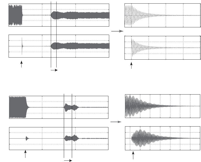
oscillation frequency. The results are compared with those for a fixed-parameter
phase compensator, of the type designed in Subsection 3.2.4,inFig.3.35. It can be
seen that, although the fixed parameter loses control after the length of the tube is
varied, the adaptive controller maintains control.
The same STR was recently applied to a lean premixed prevapourised combus-
tion rig operating at atmospheric conditions, in which modulation of the fuel supply
was used for actuation [151]. The primary instability was reduced by up to 30 dB, and
initial robustness studies confirmed that the controller retained control for a 20%
change in frequency and a 23% change in air mass flow rate.
Because of their applicability to a wide range of combustion systems and the
fact that stability can be guaranteed, STRs hold real promise in terms of future im-
plementation in full-scale combustion systems. Recent work extended their use to
combustors with higher relative degree and significant time delays [134, 152, 153],
combustors exhibiting undesirable reflections from boundaries [149], and combus-
tors with an annular shape exhibiting multiple instability modes [150]. Work on how
to extend the adaptive algorithm to more complex combustion systems is ongoing.
FULL-SCALE IMPLEMENTATION OF ACTIVE CONTROL. Although many sophisticated
feedback controllers have been applied to combustion models and laboratory-scale
rigs, there have been very few reported full-scale demonstrations of feedback control.
All used fuel modulation and very simple (and in many ways restrictive) controller
designs.
3.2 Control Strategies for Combustion Instabilities 201
0 5 10 15
−1000
−500
0
500
1000
Time (s)
0 5 10 15
−4
−2
0
2
4
Time (s)
V
c
(Volts)
2 2.05 2.1 2.15 2.2
−500
0
500
Time (s)
2 2.05 2.1 2.15 2.2
−4
−2
0
2
4
Time (s)
L varied from 75 to 105 cm
control ON
control ON
0
-500
500
0
Zoom in
2.5 2.6 2.7 2.8 2.9 3 3.1 3.2
−500
0
500
Time (s)
2.5 2.6 2.7 2.8 2.9 3 3.1 3.2
−1
−0.5
0
0.5
1
Time (s)
0 5 10 15
−1000
−500
0
500
1000
Time (s)
0 5 10 15
−4
−2
0
2
4
Time (s)
control ON
L varied from 75 to 105 cm
control ON
0
-500
500
Zoom in
(a) Fixed first-order compensator
(a) Adaptive first-order compensator
P
ref
(Pa)
V
c
(Volts) P
ref
(Pa)
V
c
(Volts) P
ref
(Pa)
V
c
(Volts)
P
ref
(Pa)
Figure 3.35. Control of Rijke tube under varying tube length L (from [134]).
The first full-scale demonstration was in 1988 on the afterburner of a Rolls-
Royce RB 199 military turbofan engine [118]. Actuation was achieved by spilling
fuel from the engine, rather than adding it, using high-response electrohydraulic
servovalves. The modulated fuel was approximately 5%–10% of the mean. Using
a simple gain–time-delay controller, a 12-dB reduction in the dominant low- ‘buzz’
frequency was obtained.
A decade later, active control was performed on a Siemens heavy-duty industrial
gas turbine [117, 154]. The combustor was annular, and the unstable modes were
azimuthal. The pressure at several locations around the combustor circumference
was measured, with a separate control system used at each location. Actuation was
performed by modulating the fuel to the pilot flames by use of a high frequency
solenoid value supplied by MOOG. Simple gain–phase-shift controllers were used,
and the dominant frequency was reduced by 17 dB. It was found that the required
controller parameters changed with operating condition.
Researchers at United Technologies Research Center then demonstrated active
control on full-scale liquid-fuelled lean premixed combustors [124, 155]. With a
solenoid valve to modulate the fuel supply, a 16-dB reduction of the dominant
mode in a single combustor and a 6.5-dB reduction in a 67.5
◦
sector cut from a full
combustor annulus were obtained.
202 Combustion Instabilities
The adaptive phase-shift controller discussed in Subsection 3.2.4 [105] was also
applied at full scale to a Siemens-Westinghouse Dry Low NO
x
combustor [144]. The
dominant mode was reduced by 15 dB, and the NO
x
emissions were reduced by
approximately 10%.
3.3 Simulation of Thermoacoustic Instability
By L. Gicquel F. Nicoud and T. Poinsot
As noted in previous sections, thermoacoustic instabilities arise from the coupling
between acoustic waves and flames and can lead to high amplitude instabilities
[29, 74, 75, 156]. In general, these instabilities induce oscillations of all physical quan-
tities (pressure, velocities, temperature, etc.); in the most extreme cases, they can de-
stroy the burner by inducing large-amplitude flame motion ( flashback) or unsteady
pressure (material fatigue). Because the equivalence ratio oscillates when instabil-
ities are present, there is a general trend for combustors to be more unstable when
operating in the lean regime. Also, because of new international constraints, pollu-
tant emissions must be reduced and gas turbine manufacturers need to operate their
systems under leaner and leaner conditions. Consequently there is a need to under-
stand combustion instabilities and to be able to predict them at the design level [157].
The objective in the following subsections is to provide the reader with the rel-
evant information regarding the description, modelling, and computation of thermo
acoustic instabilities. The basic equations are first recalled in Subsection 3.3.1. Among
the possible levels of description, two are discussed in more detail in the subsequent
subsections, the large-eddy simulation (LES) approach in 3.3.2 and a 3D linear
description based on the Helmholtz equation in 3.3.3. Because using appropriate
acoustic boundary conditions is critical when analysing combustion instabilities, this
issue is discussed in Subsection 3.3.4. Finally, the different tools and approaches
discussed are used to study the thermoacoustic behavior of an industrial annular
combustor in Subsection 3.3.5.
3.3.1 Basic Equations and Levels of Description
Three types of numerical or semi-analytical methods have been considered so far to
predict and describe these instabilities:
1. LESs of all relevant scales of the reacting, turbulent, compressible flow where
the instability develops. Many recent studies demonstrated the ability of this
method to represent flame dynamics [158–164], as well as the interaction between
reaction zone and acoustic waves [165–168]. However, even when simulations
confirm that a combustor is unstable, LES calculations do not say why and how to
control the instability. Besides, because of its intrinsic nature (full 3D resolution
of the unsteady Navier–Stokes equations), LES remains very CPU demanding,
even on today’s computers (CPU stands for central processing unit).
2. Low-order methods in which the geometry of the combustor is modelled by a
network of homogeneous (constant-density) 1D or 2D axisymmetric acoustic el-
ements for which the acoustic problem can be solved analytically [102, 119, 169–
172]. Jump relations are used to connect all these elements, enforcing pressure
continuity and mass conservation and accounting for the dilatation induced by
