Swaminathan N., Bray K.N.C. (eds.) Turbulent Premixed Flames
Подождите немного. Документ загружается.

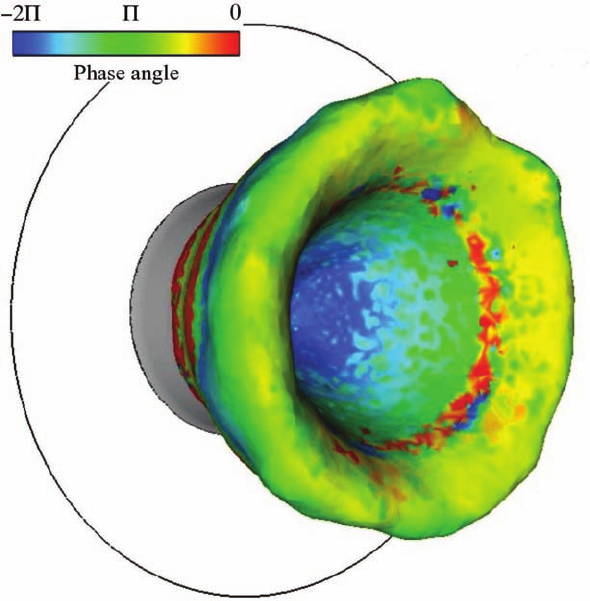
Figure 3.40. Forced turbulent premixed flame in a real gas turbine configuration: isosurface
of heat release coloured by the local value of the delay as an estimate with LES and the
classical n − τ model [198].
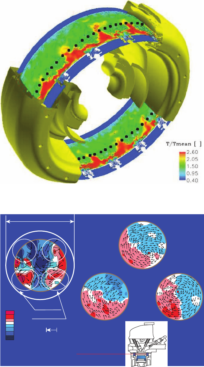
Figure 3.44. 3D view of the computational domain; temperature field on a cylindrical plane
passing through all the swirlers with velocity magnitude isocontours. Black dots denote typical
problem locations for which diagnostics are subsequently provided.
Cylinder Bore
(a) 450° CA
(b) 540° CA
(c) 600° CA
660° CA
exhaust
intake
Primary Valve
Secondary Valve
Vh: 20m/sec
Measurement Plane:
16mm below the spark plug gap
Timing:
ignition timing (BTDC40*)
V axial (m/sec)
20
10
0
10
20
30
Figure 4.16. Three components of phase-averaged velocity at four crank-angle (CA) posi-
tions measured by the particle coded-pulse velocimeter. Note that the diameter of the field of
view through the piston crown is less than the bore of the engine. Firing TDC is at 720
◦
CA
[73].
Exhaust
Spark plug
Intake
(a) Injuction = 0° CA
Measurement Plane:
8mm below the spark plug gap.
Timing:
ignition timing (BTDC40°)
Valve lift and timing for VTEC-E mode
(b) Injuction = 20° CA (b) Injuction = 55° CA
Start of Intake Stroke
Middle of Intake Stroke
10
Exhaust Intake
c
h
a
Primary valve
8
6
4
2
Valve lift (mm)
0
Secondary valve
Chank Angle (deg.)
-180
(BDC)
O
(TDC)
180
(BDC)
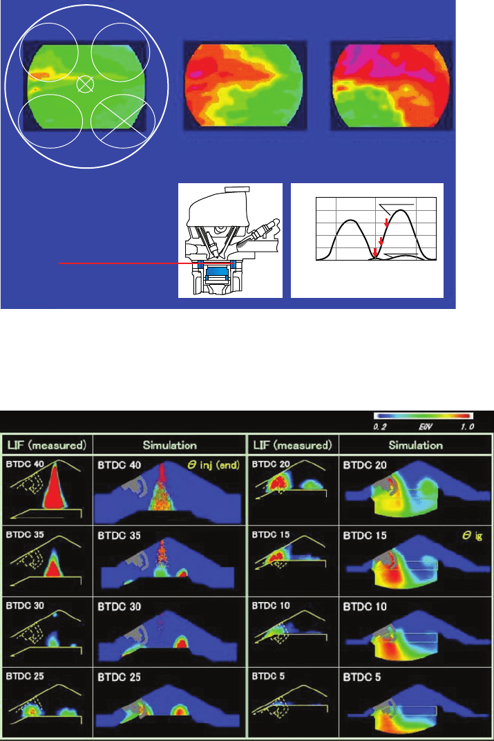
Figure 4.18. Contours of tracer PLIF measurements of fuel concentration near the spark-
plug electrodes as functions of the start of injection timing (
◦
CA afer TDC). Red is relatively
richer, yellow is relatively leaner. Intake TDC is at 0
◦
CA.
Figure 4.24. In-cylinder mixture formation: Comparison between PLIF and CFD as functions
of the CA of the end of injection. Modified from [82]: Scale for equivalence ratio applies to
CFD quantitatively, to experiment qualitatively. PLIF, planar laser-induced fluorescence.
Mixture preparation Flow field
BTDC 40deg.
BTDC 25deg.
BTDC 15deg.
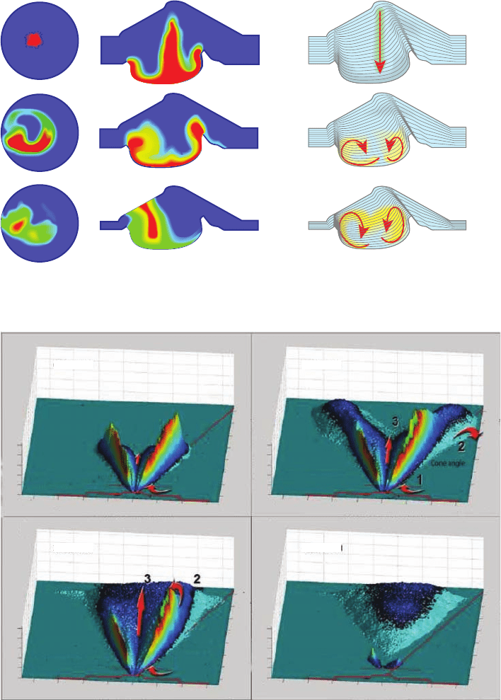
Figure 4.25. CFD predictions of in-cylinder mixture preparation [82].
250
200
150
100
50
0
250
200
150
100
50
0
0
0
5
10
15
20
25
30
35
Distance from nozzle (mm)
Upper laser plane boundary
Upper laser plane boundary
Upper laser plane boundary
Cone angle
Cone angle
Cone angle
Cone angle
Upper laser plane boundary
Distance from nozzle (mm)
0
5
10
15
20
25
30
35
Distance from nozzle (mm)
0
5
10
15
20
25
30
35
Distance from nozzle (mm)
5
−5
10 15
−10−15
−20
0
Distance from nozzle (mm)
5
−5
10
15
−10
−15
−20
250
200
150
100
50
0
250
200
150
100
50
0
0
0
5
10
15
20
25
30
35
Distance from nozzle (mm)
Distance from nozzle (mm)
5
−5
10
15
−10
−15
−20
0
Distance from nozzle (mm)
5
−5
10
15
−10
−15
−20
1.5 ms ASOI0.76 ms ASOI
4.13 ms ASOI3.59 ms ASOI
A B
C D
Figure 4.34. Multihole nozzle: direct imaging results using laser-induced exciplex fluores-
cence from a 50
◦
‘umbrella’ multihole nozzle, showing qualitative time-resolved results from
measurements made in a chamber at 10 bars and 584 K. The results were processed so that the
vapour concentration is shown by the magnitude of the z axis, and the liquid concentration
is represented by the colour, red–high, blue–low in the z axis. ASOI is after start of injection
[95].
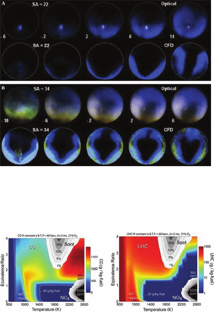
Figure 4.37. Effect of two values of ignition timing (denoted as SA = 22 and SA = 34, in
units of degrees CA BTDC) on the progress of combustion in a spray-guided stratified-charge
DI engine. Top row of each two-row set: visualisation through ensemble-averaged spectrally
resolved imaging: OH* chemiluminescence (blue) and radiative emission from soot (red and
green). Bottom row of each two-row set: CFD calculations of heat release rate (blue) and rich
combustion products (yellow) [87].
Figure 4.47. Left, CO yield at 2.0 ms obtained from a homogeneous reactor simulation of
an n-heptane–air mixture, using the LLNL detailed n-heptane mechanism. The 88-g/kg-fuel
isopleth corresponds to 2% of the fuel energy in CO [154]. Right, UHC yield for the same
conditions as in the figure on the left.
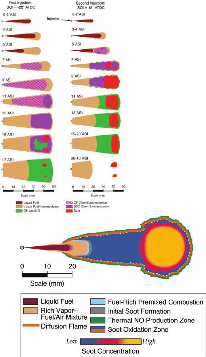
Figure 4.48. Schematic representation of
the spray, combustion and emissions pro-
cesses for the low-temperature, double-
injection (UNIBUS-like) condition (first
injection in left column and second injec-
tion in right column) [159]. SOI is start of
injection, ASI is after start of injection
Figure 4.49. A schematic of the conceptual model of conventional diesal combustion with
additional features (fuel-rich premixed flame, soot formation, soot oxidation, and NO forma-
tion zones) that are indicated by the data but have not yet been verified (J. E. Dec, personal
communication and [161]).
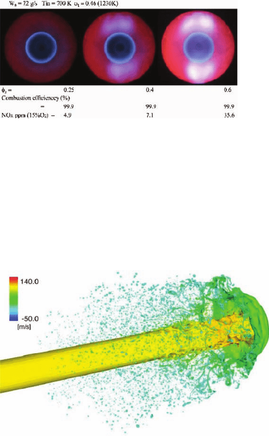
Figure 5.3. Photograph of flames in primary and secondary stages.
Figure 5.13. Detailed simulation of atomization process of liquid jet [23]. The suface colour
shows the axial velocity.
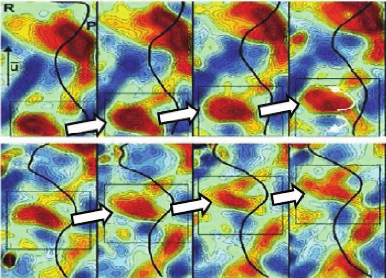
Figure 5.20. High-speed movies of eddy–flamelet interactions in the fully turbulent premixed
Bunsen flame of Steinberg et al. [69]. Time between images is 0.66 ms. Field of view is
4mm× 8 mm. The Black line is the flame surface. Contours of vorticity vary from −1000 s
−1
(blue) to 1000 s
−1
(red). Flow is from bottom to top.
