Smith G.T. Cutting Tool Technology: Industrial Handbook
Подождите немного. Документ загружается.


Figure 252. In-process gauging, used for up-dating the cutting process voiding ‘tool-drifting’ during
a production run. [Courtesy of Mahr/Feinpruf]
.
Machining and Monitoring Strategies 513

as that depicted in Fig. 251b. Aer rough-milling,
any semi-nishing and nishing operations can be
undertaken in the hardened condition,
2. H
ard-part milling – this is mainly where small-di-
mensional parts, or components requiring the pro-
duction of shallow-cut features that can be readily
milled (e.g. threads – Fig. 251a; gears and hobs –
Fig. 251c) – in the hardened state,
3. E
lectrical discharge machining (EDM) – is usually
utilised when the part incorporates thin features,
requiring deep cuts, thus the EDM process may be
the only practical solution to this problem.
Hard-Milling – Tool Selection and Replacement
For most die and mould operations, selecting the ap-
propriate cutter geometry is important, with many op-
e
rators choosing ball-nosed end mills (Fig. 249 – bot-
tom right) for such hard-part milling work. Such
g
eometry is chosen for rouging and nishing oper-
ations, because the tool’s large radius dissipates both
the heat, while ‘spreading’ the cutting forces across its
longer cutting edges. Additionally, the ball-nose end
mill enables the user to cut closer to the net shape of
the part’s geometry at high speeds and feeds. When a
part incorporates wide and at areas across its base
– needing to be milled, a corner-radiused tool should
ideally be utilised aer the surface has been roughed-
out with the ball-nosed tooling. e logic behind em-
ploying the corner-radiused tool for nishing, is that
with its smaller radius it cannot dissipate the heat and
f
orces as readily as the ‘ball-nose’ , this is why it is usu-
ally used for semi-nishing/nishing operations when
hard-part milling. If a square shouldered part feature
is needed, then a ‘square-ended tool’ is only used aer
the ‘ball-nose’ has roughed-out the component’s fea-
ture – leaving the minimum of stock to be removed.
is ‘square-ended’ cutter – due to its sharp corner, has
a tendency to chip/fracture, since it acts as a ‘stress-
raising source’ for the heat and cutting forces.
Tool rigidity is important, with the tool’s shank
being much larger in diameter to that of the cutting
diameter. With ball-nosed cutters, a small dra an-
gle of about ½° is employed for additional strength,
while the tool’s neck is usually slightly-relieved when
HSM milling straight walls. In both of these cases, the
tool’s projection from its holder should be kept to a
minimum – to improve its intrinsic rigidity. Returning
briey to the former case of the cutter having a dra
angle. Another reason for the ½° dra angle when ma-
chining dies and moulds, is that if for example, when
the hardened die has a dra angle of 5°, the cutters
modied relief should be ½° clearance, producing an
included angle of cutter body relief of 4½°.
D
uring machining a die cavity (Figs 246 – bot-
tom right and 249b), the excessive heat that is gener-
ated modies the part’s surface topography, which in
turn, reduces component accuracy. One technique to
m
inimise such heat generation and retention while
milling, is by controlling the radial step-over (i.e. pick-
feed) distance for adjacent tool paths – when taking
‘
parallel cuts’
59
(Fig. 84c). is radial step-over is the
distance between the centrelines of successive paral-
lel cuts ‘a
e (p)
’ – shown in Fig. 247b. erefore, for ball-
nosed roughing-out operations, this radial step-over
should ideally be between 25 to 40% of the cutter’s
diameter. Conversely, for nish-milling – for a given
cusp height on a at surface, the radial step-over can
be calculated, as follows (Fig. 247b):
R
adial step-over (mm) = √4(a
p
× D
e
) – 4 (a
p
2
)
Where: cusp height is the chordal deviation – nish
tolerance, thus, a
p
= cusp height (mm), D
e
= tool diam-
eter @ a set D
OC
(mm).
Cusp height (mm) = D
e/
2 – √ (D
e
2
– a
e (p)
2
)/4
Where: a
e (p)
= radial step-over (mm).
(Sources: adapted from Sandvik Coromant, 1994; Ma-
carthur, 2001)
Since, the radial step-over determines the length of
time each cutting edge spends in the actual cut, in
conjunction with the amount of time it has to cool,
prior to re-entering the following cutting-pass. is
in eect, simplistically determines the quantity of
heat that will accumulate in both the tool and the ma-
chined workpiece. So, when the radial step-over is too
wide, the heat builds-up in the cutter’s edge, due to the
fact that there is insucient time for it to conduct the
heat away, before it re-enters the following cut. While,
smaller step-overs can facilitate ‘almost’ a continuous
cooling action, which limit’s the heat generation and its
59 ‘Parallel cuts’ – when milling, are sometimes referred to as
‘lace cuts’. If they are not parallel – such as when pocket-mill-
ing a triangular feature, where parallel cuts would be ineec-
tive, then the technique here is to utilise variable step-over
cuts, termed: ‘non-lace cuts’.(Source: Smith et al., 1993)
514 Chapter 9

retention, allowing a slightly higher cutter rotational
speed to be programmed. A suitable coating selec-
tion for example, on a cemented carbide cutter, will
also enable higher speeds to be realised. In hard-part
milling operations, coatings, such as: titanium car-
bonitride (TiCN) can withstand temperatures up to
400°C, comparing this to titanium aluminium nitride
(TiAlN), which can withstand cutting temperatures of
up to 800°C, indicates for many hardened alloy steel
dies and moulds, the latter coating makes for a wiser
choice in these production circumstances.
e selection of speeds and feeds will also aid in
controlling heat build-up. With large chip thicknesses
helping to remove heat build-up in the tool and work-
piece. When chip loads are too light, the heat quickly
builds-up – as edges tend to rub the surface being
milled, which in turn, aects tool life and may create
‘white-layering’ in the sub-surface in steel-based prod-
ucts. So using the largest possible chip loads improves
through-put of parts. By way of illustration, if the chip
l
oad per tooth should be 0.2 mm, but instead it is only
0.05 mm, then a workpiece that normally takes around
18 minutes to machine, will now actually take 72 min-
utes. is increased time means the tool’s edge will
now spend 400% longer in-cut.
Flood coolant should not be used when adopting an
HSM milling strategy for hardened metals (>40 HR
C
).
In the USA some industrial trials were conducted into
milling such hardened workpieces and, it was reported
that by not using ood coolant then tool life was in-
creased by 500% – on average. ese trials including
various methods of coolant delivery, via: through-
the-tool coolant holes; coolant grooves; coolant hoses;
and for normal- and high-pressure coolant applica-
tions; in all cases the tool life was reduced. e main
problem with the various forms of coolant delivery
it would seem, is the result of the cemented carbide
tooling suering from ‘thermal-shock’ ,
creating by
the high tool/chip interface temperatures and the im-
mediate ‘quenching-eect’ of the coolant application
– this ‘thermalcycling behaviour’ occurring at very
fast rates. Nonetheless, work-hardened chips in the cut-
ting vicinity must still be evacuated from deep recesses
and pockets to avoid the ‘recutting eect’. By using an
air-and-mist application – close to the tool’s edge, this
will provide a means of swarf removal, while produc-
ing some ‘token’ cutting edge lubrication – assuming
that ‘coolant-eect’ permissible exposure levels (PEL’s)
can be safely dealt, thereby with minimising potential
health hazards.
Any decisions concerning tool replacement will de-
pend on the users machining needs, with the tool fail-
ure generally being apparent by the naked eye, or un-
der low optical magnication – simply observing the
cutting edges to determine the ‘wear-patterns’. In-cut,
a worn tool’s edges will tend to emit a dull ‘red glow’
60
,
this indicates that excessive forces and heat are being
generated in the cutting zone, shortly leading toward a
r
apid and catastrophic tool failure condition. is ‘vis-
ual glowing eect’ is initially usually conned to the
60 ‘Tooling – glowing red’ , this temperature-induced machining condition has been widely reported. Trent, 1984, stated: ‘Under very ex-
ceptional conditions, when cutting fully hardened steel, or certain nickel alloys at high speed, chips have been seen to leave the tool red
hot* – i.e. a temperature of over 650°C’.
*is term ‘red hot’ – relating to temperature is somewhat vague, as shown in the chart, for: Variation of colours with temperatures
– tempering, stress relief and hardening:
Colour: °Fahrenheit: °Celsius: Colour: °Fahrenheit: °Celsius: Colour: °Fahrenheit: °Celsius:
Straw yellow 430 220 Light blue 590 310 Faint red 950 510
Light brown 465 240 Grey 615 325 Dark red 1150 620
Brown 520 270 Grey-purple 660 350 Dark cherry 1175 635
Purple 545 285 Grey-blue 705 375 Cherry red 1300 705
Dark blue 565 295 Dull Grey 750 400 Bright cherry 1470 800
NB Temperatures above are either slightly rounded-up, or -down. Conversion: °Celsius = 5/9 (°F - 32)
(Sources: Avner, 1974; Bofors, 1981)
Machining and Monitoring Strategies 515

cutting edge corners – where high stresses and tem-
peratures are generated, which can be precisely tem-
perature-monitored by thermographic equipment
61
, or
simply rather crudely, by naked eye observation – with
the machine tool’s lights turned out!
So, by applying the correct tooling in a consistent
and repeatable manner, becomes a vital factor for any
form of predictability with all hard-metal machining
applications. is is also particularly true for any form
of hard-part: drilling; reaming; and tapping opera-
tions; where these production processes oer serious
challenges to the cutting edges, as the bulk hardness of
the workpieces increase to >40 HR
C
.
9.10 Ultra-Precision
Machining
Introduction
In the last few years, there has been a momentous drive
toward producing components and indeed assemblies,
signicantly more minute than was previously the case.
e demand might be to locate and align mechanical
parts together in much closer proximity, or perhaps,
oering improved functionality and providing en-
hancement of power-to-weight ratios necessary for
electronic micro-circuitry. In fact, the adjacent circuit
dimensions for nanometric electronic devices can have
a
proximity to each other of: 0.000006 mm (i.e 6 nm ≡
6 × 1
0
–9
m).
61 ‘ermography’ , utilises the infra-red radiation emitted by
a temperature-induced body. ese thermographic cameras,
oer considerable benets to any form of actual temperature-
monitoring applications. ermal gradients, hot-spots and
heat losses can be observed – by ‘line-of-sight’ measurements
– during actual machining operations. ey can also be used
to assess temperatures in electrical cabinets, servo-motors,
ballscrews, etc., for actual condition monitoring of the ma-
chine tools. (Source: Smith et al., 1996)
NB Typical temperature ranges for thermographic cameras
are: –40°C to >2,000°C with a thermal sensitivity of 0.08°C,
making then ideal for some forms of tool temperature moni-
toring – assuming that the chip-stream is away from the cam-
era’s lens. (Source: Flir Systems™)
e challenges for the whole of the ultra-precision
manufacturing industries, are to be able to make and
supply miniscule devices that will meet these latest de-
sign objectives. Before, discussing the tooling require-
ments and machining techniques necessary to pro-
duce these diminutive parts, oen with a high volume
demand. It is worth trying to comprehend the ‘true
dimensional size and scale’ of these miniature compo-
nents and assemblies.
Previously, the term ‘hair’s breadth’ was oen
quoted as a very minute dimensional size, but if
one looks at Fig. 253a, here, the large circle is sup-
posed to represent the diameter of an actual hair
– for comparison. Although even here, a hair is not
of uniform diameter. In some very simple comparison
tests undertaken about 6 years ago (Smith, 2002). He
plucked one of his own hairs from his head – that he
could not really aord to miss!, plus four more from
several other people in the vicinity! en, he located
this group of hairs within an scanning electron mi-
croscope (SEM) chamber and simply measured them.
e surprise was that they varied quite considerably,
ranging from the smallest hair: at φ3
0 µm to that of the
largest hair at: φ1
00 µm. So, the diagram (Fig. 253a) in-
dicating that the hair’s size was ≈φ8
9 µm is somewhat
misleading as a form of measurement criteria, as we
will begin to appreciate, that the dierence of a few
‘microns’ can be excessively out-of-tolerance in some
ultra-precision components and assemblies. Even the
previous high-accuracy value of a ‘micrometre’ – oen
simply termed the ‘micron’ this dimensionally-being
10
–6
m (i.e. illustrated against the hair for comparison
in Fig. 253a), which is not considered and exceptional
dimensional size to ‘hold’ in today’s ultra-precision
machining world. In fact, the technical challenge now
and into the future, is not one of the actual manufac-
ture of these parts (Fig. 253b), but measuring them,
as the old statement, that: ‘We make it, then measure
it, at ten times this accuracy’ , does not hold true any-
more.
We are ‘almost routinely’ of late, making ultra-pre-
cision components at the ‘atomic levels of resolution’ ,
so how can one measure sub-atomic sized components
at the ‘absolute limits’ of today’s metrological instru-
mentation? is form of ‘innitesimal measurement’ ,
is where the term ‘uncertainty of measurement’ really
does become and important factor. ere are so many
variables in the actual manufacturing process that can
inuence the overall dimensional sizes of critical fea-
tures with these miniscule components.
516 Chapter 9
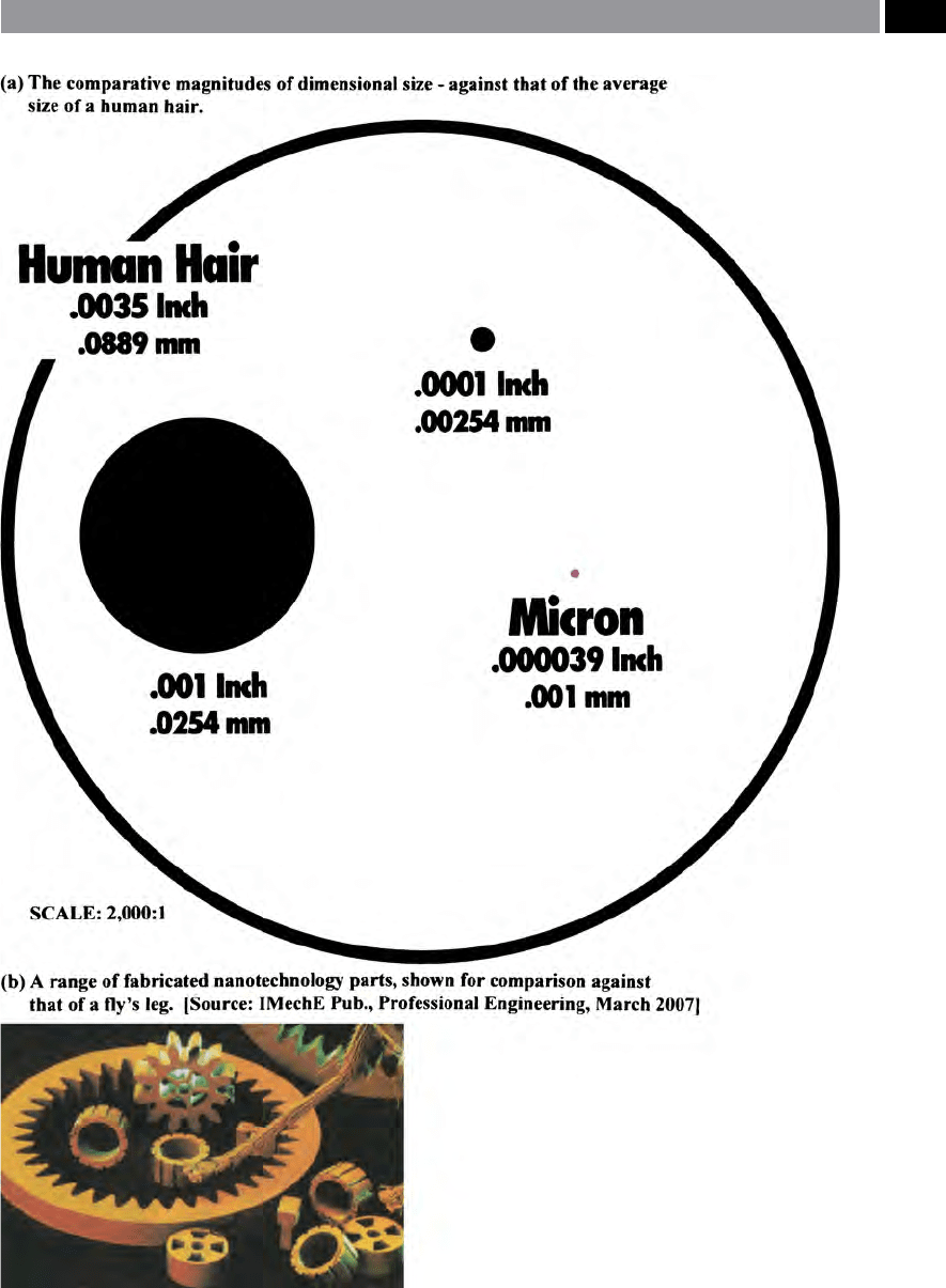
Figure 253. Micro- and nano-machining of parts is a big challenge for both today and tomorrow.
Machining and Monitoring Strategies 517

e term ‘ultra-precision machining’ – that is its
accuracy and precision, really does need to be more
clearly stated
62
. Many people wrongly surmise that ‘ul-
tra-precision manufacture’ only refers to very minute
components, but one can also relate to a large-scale di-
mensional workpiece, that has certain features for ex-
ample, its machined diameter, or face (Fig. 257b), to-
gether with its overall manufactured width, or length
(
Fig. 254 – top), to these ultra-precision dimensions.
In recent years, the distinct challenges with respect
to ‘micro-machining’ manufacture have been reason-
ably successfully overcome, but ‘nano-machining’
(10
–9
m) and indeed, ‘pico-machining’ (i.e. 10
–12
m), is
now distinctly on the horizon (i.e see Fig. 254, for an
indication of the relative ‘sizes and scales’ demanded –
of late. ese latter machining operational strategies,
oering simply massive challenges in terms of the:
•
Production environments – controlling and moni-
toring the temperature, humidity atmospheric pres-
sure, cleanliness and dust ingress, together with any
oor- and air-borne vibrational eects,
62 ‘Accuracy’ , here and to make it more readily understood, will
be stated in distinct two ways, thus:
‘Accuracy’ , can be established by the dierence between the
actual position of the machine’s slide and the position de-
manded by the CNC, or:
‘Accuracy’ , is the conformity of an indicated value to a true
value (i.e. an actual, or accepted standard value – this being
a qualitative term only).So, the accuracy of a control system
can be expressed as the: Deviation, or dierence between the
ultimately controlled variable and its ideal value – usually in
the steady-state, or sampled instants.
‘Precision’ , on the other hand, is: e degree of discrimina-
tion with which a quantity is stated – e.g. a three digit nu-
merical, discriminates among 1000 possibilities.
NB Precision* is oen contrasted with accuracy. For exam-
ple, a quantity expressed with 10 decimal digits of precision,
may only have one digit of accuracy. (Source: Smith, 1993)
*Bell (1999) states that: ‘Precision’ , is a term meaning ‘neness
of discrimination’ , but is oen misused to mean ‘accuracy’ , or
‘uncertainty’. Its use should be avoided if possible – accord-
ing to Bell. So if this latter statement is the actual situation,
then some singular confusion reigns, when we use the word
‘precision’. In eect, we should always say: ‘accuracy and pre-
cision’ , as uniquely and simply metaphorically-depicted in the
well-known Archery: ‘Target analogy’ – for arrows hitting a
target, thus:
Wide arrow scattering, but centred (on average) on the
‘gold’ – accuracy,
Arrows o target centre (i.e. from the ‘gold’), but closely
grouped – precision,
Close arrow grouping on the ‘gold’ – accuracy and precision.
(Source: Oakland, 1986, Smith et al., 1993)
–
–
–
–
–
–
•
Work-holding security, part restraint; manufac-
turing with its potential for component distortion
– perhaps achieved by some form of ‘cryogenic ma-
chining’ , together with monitoring tool wear the
component,
•
Retrieval of parts once manufactured – this collec-
tion operation of minuscule machined parts aer
manufacture is not without problems, as at best,
they will be almost invisible to the naked eye (i.e
see some of these ‘larger parts’ manufactured in
Fig. 253b),
•
‘True’ dimensional measurements – of such ma-
chined part’s actual features, need to be measured
perhaps when in-situ as it is being manufactured,
or later, when any distortions through subsequent
handling and temperature eects have been nulli-
ed.
ese major manufacturing and measurement prob-
lems will have to be addressed in the relatively near-
future, if these latter ‘invisible to the naked eye’ parts
some of which being beyond the visible spectrum for
our sight are to be dealt with outside the ‘research
environment’ and into actual ultra-precision produc-
tion.
9.10.1 Micro-Tooling
Introduction
e question oen posed when considering mi-
cro-tooling, is: ‘What constitutes a micro-tool?’ For
exa
mple, some automotive engineering companies
might consider micro-tooling to be <φ0
.95 mm, while
others in say the aerospace industries, would set an
arbitrary level at <φ0
.55 mm, conversely, in the medi-
cal and optical industries they would be more in-
clined toward diametral values of <φ0
.06 mm. So in
eect, it all depends upon a company’s ‘working-di-
mensional criteria’ ,
rather than an actual dimensional
size. Micro-tooling – such as endmills, are currently
commercially available in the USA, that have been
manufactured to φ0
.006 mm (i.e ≡ 6 µm), sitting quite
nicely within the ‘micro-machining dimensional tol-
erance zones’. Contrast this to other company’s, who
would even consider ‘nano-machining’ to operate with
w
orkpiece dimensional features set at <0.025 mm (i.e
≡ 2
5 µm)! So, there is even some confusion as to what
constitutes either: ‘micro-’ or, ‘nano-tooling’ and the re-
spective features that they might adequately machine.
So, as a ‘start-point’ ,
if we average these (above) three
518 Chapter 9
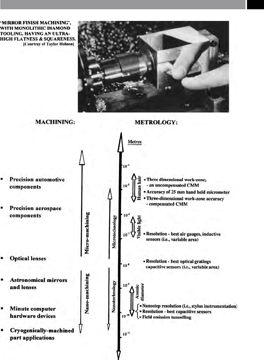
Figure 254. Relative dimensional sizes and scales, for:
• machining of accurate and presicion parts or
• equated to their respective measurement.
[Source: Smith, et al., 2002]
.
Machining and Monitoring Strategies 519

industrial-versions of what constitutes a ‘micro-tool’ ,
we obtain the following dimension for ‘our tooling’:
<φ0
.95 + 0.55 + 0.06/3 (mm) = ≈<φ0.52 mm, or by sim-
ply and conveniently rounding-down, let us consider
in our discussion, that any form of ‘micro-tooling’ is to
be set at, or below: φ0
.5 mm.
e geometric features of any ‘micro-tools’ cannot
simply be considered as minute version of ‘macro-tool-
ing’. More specically, we simply do not just scale-
down say, a φ1
2 mm drill, then manufacture its geom-
etry as a micro-tool of, for example: φ0
.25 mm drill
(Fig. 255a). Micro-tools have to be ‘engineered’ to pro-
vide eective chip evacuation, this is particularly rel-
evant when hole-making (Fig. 255b), yet remain rigid
enough to withstand the cutting forces generated and
not fracture under these conditions. In the following
sections concerning this review on micro-tooling, the
production processes of: drilling; milling; and boring
tools; will be briey mentioned.
Micro-Drills and Drilling
Probably the most signicant dierence when about
to utilise these minuscule tools, compared to their
macro-drilling counterparts, is that an operator can-
not even see what size they are, without suitable visual
magnication! is means that a micro-drill’s careful
handling – of these fragile tools, plus their safe stor-
age are vital. Micro-drills require correct containment
and appropriate labelling, allowing them to be readily
identied. Due to their minute diameters, micro-tool-
ing require rotational speeds of ≈1
00,000 rev min
–1
in
order to obtain the correct peripheral speeds, thereby
minimising the cutting forces acting on the micro-
g
eometry of the cutting edges. So that the minute
geometric features of the cutting edges are maintained
(Fig. 255b), it is desirable to have a very ne carbide
grain structure
63
– to strengthen the tool’s edges. If just
the smallest amount of uncontrolled lateral force oc-
curs, it can cause either tool edge fracture, or instigate
complete breakage. us, if a micro-tool’s edge is just
slightly chipped then this in itself may not adversely
63 ‘Micro-tooling materials’ , cemented carbide’s increased ri-
gidity over other tooling materials, makes is susceptible to
fracture. A good substitute micro-tool material is M-35 co-
balt steel, it is a compromise between carbide drills and those
manufactured of M-2 and M-7 HSS. Heat generated drilling
holes, will ‘roll’ a drill’s edge, thus it becomes: dull; ploughs;
and breaks. Cobalt improves drill ‘red-hardness’.
aect cutting, but a 5 µm edge-chipping on a φ100 µm
tool will radically modify the tool’s geometry and seri-
ously impair its cutting performance. is miniscule
cutting edge modication can cause the tool to break,
or damage the part’s features – requiring very careful
handling of such micro-tooling, in order to obtain the
optimum cutting performance.
A drill’s feature that needs to be modied from that
of its comparable ‘macro-drilling’ equivalent, is the
drill’s web ( i.e. see Fig. 47- bottom), this being the cen-
tral portion of the tool that extends axially along the
ute – gradually thickening as the distance increases
from the tool’s point. So for a micro-drill, the web is
proportionally thicker, because there has to be some
‘core-strength’ to a micro-tool. By way of illustration,
o
n a micro-drill a web of say just 25 µm is simply not
robust enough, as such, it would not work. To reduce
a micro-drill’s stress and prevent it from binding in
the hole, a back-taper
64
is purposely ground – playing
a major role in drilling eciency. While, another mi-
cro-geometric consideration for these minute drills is
its cutting edge sharpness, becoming of critical impor-
tance as the relative tool diameter gets smaller – this
being a limitation to eective micro-machining. For
example, on a macro-drill, if the cutting edge has a
2
5 µm cutting edge radius, it is considered somewhat
sharp, but this would hardly be the case for a micro
drill. Moreover, on a micro-drill if the cutting edge
r
adius is 10 µm and it is taking a 2 µm chip load, its
not just considered as ‘dull’ , but it is highly-negative
raked! e PVD-coating process on micro-drills can be
successfully accomplished, if the drill is manufactured
with a reduced width of edge preparation, thus main-
taining its sharpness (i.e by way of illustration, Fig 18
shows typical ‘edge-preps’ for macro-cutting inserts).
In any form of micro-drilling operation, very high
spindle speeds are necessary, for example, if a φ0
.2 mm
micro-drill is utilised, then the spindle speed should
be ≈8
0,000 rev min
–1
, in order to prevent the creation
of high drill thrust and torque forces, which might
64 ‘Micro-drill back-taper’ , this is where a slight decrease in
the drill’s diameter is being specically peripherally-ground,
decreasing in size from the drill point up to and toward the
shank.
NB Back-taper on a micro-drill is generally relieved by be-
tween: 5 µm and 13 µm; because the ute’s lengths are usually
<25 mm. Conversely, on a ‘macro-drill’ this back-taper lies be-
tween: 13 µm and 25 µm per 25 mm of length.
520 Chapter 9
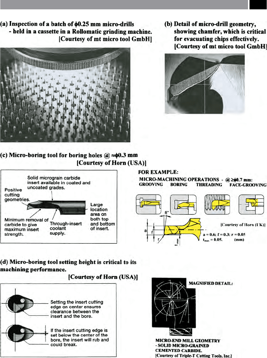
Figure 255. Some typical micro-tooling: drills and boring tools.
Machining and Monitoring Strategies 521

otherwise lead to premature tool breakage. While an-
other note of concern when micro-drilling is its pene-
tration rate. If too high a drill feedrate is programmed,
then the micro-drill will immediately fracture. Some
micro-drilling manufacturing companies either rec-
ommend a single-ute assymetric drill geometry – al-
lowing high chip loads, coupled with an ecient chip
evacuation process, conversely, another approach is to
increase the number of drill utes, but this may cause
chip evacuation problems with ‘sticky’ workpiece
materials. At present, micro-drills can normally drill
holes with L/D ratios of 5:1, but it is anticipated that
these L/D ratios will soon be up to 10:1. In any micro-
drilling operation, the rst few revolutions of the drill
are crucial (Figs. 49 and 50), as the drill’s point expe-
riences eccentric forces as it enters the cut, with any
workpiece irregularities causing the drill to ‘walk’ – re-
sulting in its bending, breakage, or at the very least
some ‘helical wandering’ (i.e axially – see Fig. 70) as
the drill penetrates into the part. In order to mini-
mise the eccentric forces as a micro-drill enters a hole,
many micro-drilling manufacturers recommend that a
pilot hole (Fig. 50b) of between 1-to-2 drill diameters
deep is produced, utilising a short and rigid pilot drill.
A pilot drill’s point angle (
i.e. see Fig. 46 – top) should
have an included angle that is either identical, or
greater than that micro-drill producing the nal hole.
If smaller included angles were selected, as the drill en-
ters the pilot drilled hole, this causes the micro-drill’s
cutting edge to chip. is tool wear-eect is because,
as the micro-drill’s more shallow point angle initially
contacts the previous pilot-drilled hole – with its more
acute angled geometry, as the micro-drill enters work-
piece, this contact will take place at the outer edges of
the lips before the drill point touches the hole’s surface.
In lieu of a pilot-drilled hole, then begin the feedrate
at somewhat less than the nishing feed, or perhaps,
utilise a ‘pecking-drilling action’ – drill to a predeter-
mined depth, partially withdraw the drill, then drill
deeper into the workpiece, once more partially with-
draw the drill, then repeat this sequence. ‘Pecking’ has
the further benet of avoiding dwell at the bottom of a
‘
blind hole’ , this being an important surface integrity
feature with work-hardening materials.
H
ole tolerances that have been satisfactorily micro-
drilled in a range of workpiece materials are of the
o
rder: ± 5 µm, with tolerance-in-roundness (TIR) of
<2.5 µm. By utilising coolant delivery at high pressure,
either through-the-drill, with the ‘larger drill sizes’;
or alternatively ood coolant for minute micro-drills;
usually allows a 30% increase in cutting speeds coupled
to extended drill life. Although care should be made
when utilising through-coolant drills
65
, as their small
coolant hole diameters will simply clog unless the cool-
ant has been passed through s
ome form of micro-ltra-
tion unit, to remove ‘nes’ and other types of potential
clogging debris.
Micro-Mills and Milling
Over the last few years, with the advances in cutting
tool materials in combination with that of cutting tool
technology, has led to signicantly smaller milling
cutter diameters with more complex geometries be-
ing produced (Fig. 255-bottom le). In fact, several
important technologies have developed during the last
decade to assist the cutting tool manufacturers to cater
for the micro-machining industries. Probably the most
important of these new technology applications is the
design and development of very high accuracy six-axis
CNC tool grinding machines, having temperature con-
trol and coolant condition monitoring – these being
key elements in the cutter-grinding process. Grinding
tolerances held by these machines on say, an φ0
.12 mm
ball-ended end mill, must be within <2.5 µm (TIR).
Complementary to these multi-axes CNC grinders,
has been the improvements in diamond grinding
wheel technology, in conjunction with appropriate
grinding wheel metrological inspection techniques,
that have contributed to the signicant advancement
in micro-tool manufacturing quality and productivity.
Whilst continuing our discussion on the cutting tool
material front, micro-milling cutters are now being
produced from extra-ne grain cemented carbides, al-
lowing sharp cutting edges in conjunction with good
milled surface nishes. For example, one Japanese mi-
cro-tooling manufacturer oers a standard range of
‘
micro-mills’ , from: φ5 µm to φ5
5 µm; in incremental
65 ‘Ethanol’ , is an alternative applied lubrication strategy, to that
of either the usual water-based ood coolant method, or by
through-the-tool delivery. Here, ethanol is a form of alcohol,
occurring naturally in the sugar fermentation process, its
benets are that it has less-than-water viscosity, enabling it to
penetrate into the tool/chip interface in a superior fashion to
that of other coolants. Ethanol is usually delivered to the cut-
ting zone in the form of a spray-mist. While another bonus
of the application of ethanol is its low evaporation point, giv-
ing it eciency in cooling and as a lubricating agent for tool
spindle speeds (i.e. of up to and including) >60,000 rev min
–1
.
Moreover, ethanol simply evaporates and this eect negates
any disposal costs, while it provides a slight ‘chilling-eect’ on
the part, minimising thermal growth problems on miniature-
sized components.
522 Chapter 9