Smith G.T. Cutting Tool Technology: Industrial Handbook
Подождите немного. Документ загружается.


is initial calibration work using the stereomet-
ric artefact, has shown that its overall positional un-
certainty when utilised for HSM accuracy and preci-
sion assessments in combination with machine tool
diagnostics, then compared to other more-exacting
inspection techniques and measurements, has been
successful. Hence, a large artefact having replaceable
machining components (disks), has proved to be a valid
means to verify the actual ‘machine tool’s health’ – in
a real sense, as it is undertaken in a loaded state, while
partaking in high-speed cutting trials. Once, the part-
program has been written, then the whole machining
activity can be completed in a relatively short time-
frame. Although admittedly, the additional metro-
logical inspection and data analyses takes sometime
to complete, but these inspection functions can be un-
dertaken while the machine tool is still in operation –
producing quality machined components.
9.7 HSM: Rotating
Dynamometry
High-speed rotating dynamometers are being utilised
across diverse elds of industry, where: hard-part ma-
chining such as die-sinking are necessary; free-form
sculptured parts are required; expensive and delicate
workpieces that need closely-monitored cutting con-
ditions; together with applied and fundamental ma-
chinability research programmes. HSM rotating cut-
ting force dynamometry, allows one to insert the unit
into the machine tool’s spindle, where it measures
the forces acting on the tool. is measurement data
are directly amplied within the dynamometer, then
radio transmitted to a specially-congured receiver
(Fig. 244). ere are many technical advantages why
a rotating dynamometer is preferred to that of its spa-
tially-stationary counterpart (i.e. platform-type: see
Fig. 237), such as:
•
Measurement occurs at the rotating tool’s cutting
edge – meaning that the cutting force near to the
cutting process is measured during engagement with
the workpiece, not a reaction force,
•
Dynamometer’s mass remains constant, maintain-
ing a uniform level of natural frequency – while in
contrast, a stationary version (e.g. a platfrom-type),
has the workpiece’s mass (i.e normally placed onto
the dynamometer) which continuously diminishes
as the machining operation takes place,
•
Its small mass provides little inertial eects, re-
maining constant throughout the machining op-
eration – unlike that of a stationary platform dyna-
mometer,
•
Spindle-mounted dynamometers can occupy/ori-
entate themselves into any position, during ma-
chining – whereas the stationary platforms have
certain volumetric space-requirements, having just
one orientation to the applied cutting forces.
Table 16. The φ10 mm hole positional deviations for the truncated frustum – based upon the three-dimensional Isosceles tri-
angle in the disks at four quadrants (from the theoretical), in terms of their radial change
Position of holes: Top disk Middle disk Bottom disk Range Mean Grand Mean
0 degree 987 941 969 46 966
↓
90 degree 978 952 953 26 961
972
180 degree 1014 986 982 32 994
270 degree 968 946 995 49 965
Range 46 45 42
Mean 987 956 975
Grand mean → 973
NB V
alues in: µm
[Source: Smith, Sims, Hope and Gull, 2001]
.
Machining and Monitoring Strategies 493
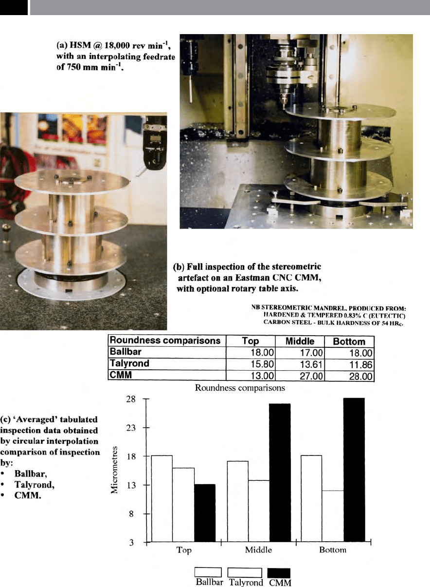
Figure 243. Technique of manufacture of the aerospace aluminium disks and the ‘averaged’ tabulated inspection data.
[Source: Smith, Sims, Hope & Gull, 2001]
.
494 Chapter 9
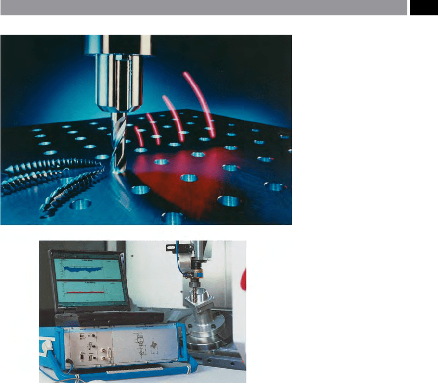
e HSM rotating cutting force dynamometer depicted
in Fig. 244, is of compact dimensions having an overall
p
rotrusion length of 106 mm, having a standard collet
chuck adaptor. With its short overall length, this HSM
dynamometer has the sensor screwed onto the sensor
bearer, giving a high moment of bending resistance,
which is reected in the small amount of ‘cross-talk’
values of radial forces on the F
Z
-force component (i.e.
F
Radial
→
F
Z
).
e rotating HSM dynamometer was designed to
have a ‘ceiling-speed’ in accordance with ISO Stan-
dard: 15641: 1998, which species a test speed of
4
0,000 rev min
–1
. Although the manufacturer originally
tested the antenna casing up to speeds of 56,000 rev
min
–1
, corresponding to a centrifugal acceleration of:
a
Zcentrifugal
= 130,000 g.
Any HSM tooling assembly, such as a rotating dy-
namometer must be balanced with particular care, in
this case, there is a pre-balance quality of 6.3 for the
antenna casing and sensor, with the nal balance be-
ing 2.5 g-mm, which ensures that the cutting force
measurements are not adversely aected.
e overall compact construction minimising ac-
celeration masses (i.e. weighing just 5.3 kg) for this
HSM rotating dynamometer, with its low-level of
n
atural frequency, having both a very low response
threshold coupled to high resolution precision, pro-
vides ‘sound’ cutting force and torque information
making it an ideal ‘tool’ for either qualitative, or quan-
titative machinability research work. Hence, the signal
quality achieved by this instrument, makes it possible
to utilise this HSM rotating cutting force dynamom-
Figure 244. A high-speed rotating
cutting force dynamometer, employed
during drilling and multi-axis milling
operations. [Courtesy of Kistler Instru-
mente AG]
.
Machining and Monitoring Strategies 495

eter, to monitor minute process interference for the
control of critical machining processes, such as: in
the development of new cutting tools; or during the
‘ramping-up phase’ from initial workpiece prototyping
to that of small batches, or even up to component mass
production.
9.8 Complex Machining:
of Sculptured Surfaces
Introduction
In today’s world of rapidly developing CAD/CAM sys-
tems with components expected to have a short lead-
t
imes coupled with a ‘streamlined appearance’ , many
of these parts and assemblies have components that
exhibit complex double-curvatures to there shapes
and proles. ese so-called ‘sculptured surfaces’ are
so-called, because they appear to have been carved,
rather than machined requiring complex tool paths to
initially machine these convex and concave blended
proles. ese sculptured surfaces oen necessitate
at least a ball-ended cutter and an 3-axis milling op-
eration, or the more likely scenario being by 5-, or
6- axis milling, using a cylindrical cutter’s periph-
ery and tip to follow the desired contour. So, with a
5-axis machining operation, the direction of a mill-
ing cutter’s axis must be adjusted to the geometry of
the workpiece’s surface curvature, by a tilting the tool
head (Fig. 245b) to produce a uniform cutting opera-
tion, regardless of the complex contour being milled.
As we will see shortly in the following section, any
free-form surfaces can only be approximated by mill-
ing, as a tool path’s groove produced (i.e. its resulting
‘cusp’) is mainly determined by the ‘
pick-feed’
39
(i.e see
Fig. 245a). So, free-form surfaces can only be approxi-
mated by milling (i.e see Figs. 246a, 247a and 248), as
a grooved (i.e. cusped) prole is generated, which is
39 ‘Pick-feed’ , or as it is sometimes represented by the term:
‘a
e
(p)’ is illustrated in Fig. 247b, which refers to the ‘step-over
distance’ for the adjacent tool path. us, the ‘pick-feed’ can
vary depending upon the required chip-thickness for the
operation currently being undertaken, which inuences the
milling tool’s cutter-loading. is cutting force will be modi-
ed, as the contoured prole’s geometry also changes during
the sculptured surface’s milling operation.
strongly inuenced by the width of the pick-feed. is
milled contour on the convex/concave, or ‘parabolic
c
urved surfaces’
40
will necessitate a hand-nishing op-
eration aerward (i.e grinding and perhaps, polishing
for high-quality die-cast, or injection-moulded ‘end-,
or nal-product’ nishes). However, due to the high
feedrates that can be utilised when adopting an HSM
milling strategy, cutter paths can be much more closely
spaced (i.e the pick-feed widths can be reduced). is
HSM scenario will considerably reduce the resultant
milled cusp height (Fig. 245a), enabling faster, or in
some cases no workpiece nishing-o processes being
necessary.
In the die and mould industry, it is the norm to em-
ploy HSM by milling, to produce the cavities and in-
tricate features required for the nal cast, or moulded
part. A range of cutters are generally utilised to gen-
erate and form the workpiece’s free-form proles,
ranging from say, tooling such as, large ball-ended
slot-drills, down to very small diameter ball-nosed
endmills (i.e see Fig. 245c).
9.8.1 Utilising the Correct Tool
for Profiling: Roughing
and Finishing
In the rst instance and, to ensure that the correct
choice of highly-productive cutting tools are employed
in the manufacture of for example, a die and mould
set, the following logical sequence could be adopted:
•
e actual geometry of the die, or mould requiring
machining operations, should be carefully studied,
to identify applicable tools and techniques for metal
removal,
40 ‘Parabolic curved surfaces’ , can be mathematically-dened as
simply: y = x
2
, although if we want to express this equation in
words, we can say that a parabola is: A plane curve generated
by a point moving so that its distance from a xed second point
is equal to its distance from a xed line. [or] A parabola changes
both its radial length with its associated angle and has a unique
focal point.
NB ‘Parabolic interpolation’ , can be achieved by controlling
the milling cutter’s path by interpolation between three xed
points, by assuming the intermediate points are on a Parabola.
Such machining action, normally requires sophisticated CAM
soware to achieve this complex kinematic motional control by
the machine tool. (Sources: Smith, 1993, Stroud et al., 2001)
496 Chapter 9
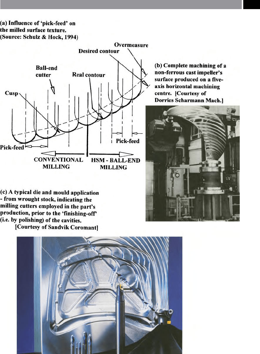
Figure 245. The complex machining of either a sculptured, or die and mould surfaces, will usually necessitate both
multifarious and sophisticated programming techniques
.
Machining and Monitoring Strategies 497

•
Dening the minimum radii requirements and the
maximum depth of the cavity, needs consideration,
ensuring selected tooling can cope with these part
geometries,
•
Approximately estimate the amount of excess stock
material from the die, or mould that needs to be
removed by milling operations
41
,
NB Establishing what is roughing-out and semi-
nishing operations, will for a large die-set oen
mean that roughing-out is both more ecient and
productive on conventional-speed machining cen-
tres, with any semi-nishing undertaken by HSM.
•
In preparation and prior to milling, ensure that the
workpiece xturing is both accurate and precise as
well as very robust and rigid, otherwise this latter
factor in particular, is a classic source for any resul-
tant vibrations and will signicantly inuence the
tool’s life together with degradation of the die and
mould surfaces
42
,
NB HSM requires a totally rigid xturing, if vibra-
tional tendencies are to be minimised, as it proves
disastrous for any long length-to-diameter tool
ratios, that are oen utilised for high-speed milling
operations.
•
For the machining processes, they should ide-
ally be divided into at least three types of milling
41 ‘Material removal rate’ for HSM milling is generally consider-
ably smaller than in conventional machining (i.e except when
aluminium and non-ferrous machining occurs). Formula for
material removal rate
Q =
a
p
� a
e
� v
f
( cm
min
−
)
Where: a
p
= axial D
OC
(mm); a
e
= radial D
OC
(mm); v
f
= feed per
minute (mm min
–1
).
42 ‘Die and mould milled surface texture’ , by HSM milling op-
erations dramatically reduces the manual polishing require-
ment – by reducing the resultant milled surface ‘cusp-heights’.
Oen conventional milling operations produce relatively large
‘cusps’ (i.e see Fig. 245a – resulting from the large width of the
‘pick-feed’). For example, when a large automobile bonnet (i.e.
‘hood’ – in the USA) die-set has been produced by conven-
tional milling practices, any manual polishing activities range
between: 350–400 man-hours!
NB is order of manual polishing will aect the geometrical
accuracy of the die-set. (Source: Sandvik Coromant, 2000)
operations, namely: roughing-out; semi-nishing;
nishing.
NB ‘Restmilling operations’
43
are normally under-
taken during any semi-nishing, or nishing op-
erations.
9.8.2 Die-Cavity Machining –
Retained Stock
Whenever a rough-milling operation is undertaken
with a square-shouldered cutter, this creates the well-
known ‘stair-case prole’
44
(i.e see Figs. 246 a and b) of
remaining stock that must now be removed by a semi-
nishing milling operation. e die-cavity’s cross-sec-
tional prole will signicantly inuence the amount
of stock remaining against the cavity wall, which will
create a variation in the cutting forces and have an in-
uence on tool deection. e consequence of this un-
even stock will be that when semi-nishing the prole,
it could aect the geometrical accuracy and precision
of the die, or mould. Clearly, in the schematic diagram
shown in Fig. 246a – le, the large chamfered die fea-
ture when being roughed-out for a given D
OC
, will leave
signicant material here for subsequent semi-nish-
ing. Likewise, in the cavity of the convex-to-concave
prole illustrated in Fig. 246 – right, it has signicant
stock material remaining at the lower regions of the
concave feature, obviously necessitating a following
machining removal operation (i.e. semi-nishing).
When a square-shouldered cutter is utilised with a
triangular geometry insert, it will have relatively weak
corner cross-sections (i.e. by way of illustrating this
eect of insert shape strength, see Fig. 155 – bottom),
creating a somewhat unpredictable machining behav-
iour. Triangular, or rhombic insert geometries, will
also create large radial cutting forces and as a result of
number of cutting edges, they are unexpectedly, less
economical than some other counterparts for such op-
43 ‘Restmilling operations’ , are those milling operations where
any Ball-nosed: Slot-drills; Endmills; or in some cases, toroi-
dal-geometry inserted cutters; are employed.
44 ‘Stair-case prole’ , is so-called, because it resembles an actual
stair-case when taken in cross-section (i.e. see Fig. 246). e
height and width of the remaining stock for each step, is de-
pendent upon a proportion of the actual ‘step-size’ (pick-feed)
and the D
OC
previously selected. Obviously requiring a semi-
nishing operation at the very least, to remove this unwanted
material.
498 Chapter 9
erations. On the contrary, round cutting inserts that
allow milling paths to be undertaken in any direction,
are oen specied because they provide a smooth
transition between successive tool passes, while also
leaving behind the twin benets of less and more even
stock, for later removal in semi-nishing. is residual
Figure 246. Die-sinking sculptured proles with a 90° square-shouldered milling cutter, introduces a ‘staircase eect’ on the
machined prole. [Courtesy of Sandvik Coromant]
.
Machining and Monitoring Strategies 499

eect of less additional stock produced by round in-
sert’s on the workpiece prole, is shown schematically
in both Figs. 247ai and aii and, should be compared to
Fig. 246a – this latter eect being the result of utilising
square-shouldered cutting inserts, in terms of stock to
be removed later in semi-nishing operations.
Amongst the notable benets of using round inserts,
are that they produce a variable chip thickness, which
allows for higher feedrates if compared to other insert-
shaped geometries. Round cutting inserts provide a
v
ery smooth cutting action (i.e see Fig. 246 – bottom
right: inset), because the entering angle changes from
almost zero – in the case of very shallow D
OC
’s, to that
of 90° – under certain conditions with the larger D
OC
’s.
us, at the maximum D
OC
, the entering angle is 45°
and when copying with the periphery, the angle is 90°.
is D
OC
variability using round inserts, also goes some
way in explaining why these inserts are so strong in
comparison to other insert shapes. Namely, round in-
serts with their actual ‘work-loading’ – at the cut’s ini-
tial progression – is successively built-up, rather than
almost immediately with inserts having greater enter-
ing angles, usually provided by their less-than-robust
geometry counterparts. Consequently, round inserts
should always be regarded as the primary choice in
cutter selection when either roughing, or for medium-
roughing operations. When 5-axis machining, the use
of round cutting inserts can be usefully exploited, as
they have virtually no limitations when machining
sculptured surfaces. erefore, with optimum CNC
programming, either round inserts, or toroid-shaped
milling cutters can normally be substituted for ball-
nosed end mills (Fig. 79b), as they can oer: superior
cutting performance; improved chip-breaking e-
ciencies; as well as better chip evacuation; this latter
point is important when deep cavities might otherwise
retain work-hardened swarf. Typically, the increases
in productivity range between 5-to-10 times better,
if compared to that of previously utilising ball-nosed
end mills. Round insert tooling is very rigid so as a re-
sult, they only produce a small amount of run-out and,
when combined with ground, positive and light cut-
ting geometries, may be used for semi-nishing and
o
ccasionally some nishing operations (Fig. 246 – bot-
tom right: inset).
Some of the main questions to be answered re-
garding the correct application of technology is con-
cerned with optimising: the cutting data; likely insert
grades; together with their geometries; in relation to
the: specic workpiece material to be machined; actual
machining operations to be undertaken; anticipated
productivity requirements; and the likely workhold-
ing restaint/security issues. Die and mould work in-
variably involves complex sculptured male and female
surfaces, with any calculations of the eective cutting
s
peed being based upon either the ‘true’ , or eective
diameter in-cut (‘D
e
’ – see Fig. 247b). So, if the D
OC
is
very shallow – as is the case when semi-nishing op-
erations are being carried out, then the ‘true’ cutting
speed will be much lower (Fig. 247b). If the original
cutter diameter was chosen for the cutting data calcu-
lations, then for a shallow cut – due to ‘D
e
’ being the
eective diameter, this drastic reduction in actual cut-
ting speed will not have been anticipated, causing the
feedrate utilised to be severely compromised, as it is
dependent on the calculated cutter’s rotational speed.
is will not only severely impede component produc-
tivity, but will increase the tool’s potential wear-rate
signicantly, this being the case for all round insert
cutters, ball-nosed end mills, plus end mills having
large corner radii. Due to the adverse and miscalcu-
lated cutting data, there is a likelihood for premature
cutting edge frittering and chipping – created by too
low a cutting speed and localised heat in the cutting
zone. When undertaking either nishing, or super-n-
ishing of the die and mould sculptured surfaces (Fig.
246biii) on hardened tool steel, it is vitally important
to choose tool materials and coatings with ‘hot hard-
ness’ capabilities
45
.
A major factor to consider when milling for either
nishing, or super-nishing hardened steel sculptured
surfaces by HSM, is to take shallow cuts. Notably, the
D
OC
should not exceed 0.2/0.2 mm (a
e
/a
p
– Fig. 247b).
is strategic machining decision should be made, so
that excessive deection of the cutting tool assembly is
avoided, enabling a high tolerance level and geometric
accuracy to be held on the die, or mould. Accordingly,
very sti tool assemblies are essential, usually utilising
solid cemented carbide: due to its inherent stiness;
coupled with the maximum core diameter possible;
that the die, or mould part features will allow.
45 ‘Tool materials for: hardened steel milling’ , they are usually
coated cemented carbide, with the micro-grain structural
matrix (i.e. typical grain size being <1 µm), providing good
wear resistance and transverse rupture strength (i.e. this be-
ing ‘related’ to its toughness). Coatings can include: titanium
aluminium nitride (TiAlN); titanium carbonitride (TiCN);
having multiple coatings of between 2 to 12 µm thick, applied
by Plasma Vapour deposition (PVD). Diamond-like coatings
(DLC) are also utilised. (Source: Dewes and Aspinwall, 1996)
500 Chapter 9
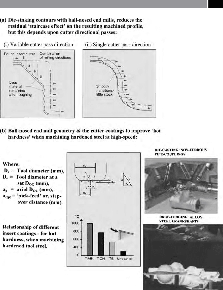
Figure 247. By utilising a ball-nosed cutter geometry for die-sinking sculptured surfaces, this reduces nishing stock needed to
be subsequently removed. [Courtesy of Sandvik Coromant]
.
Machining and Monitoring Strategies 501

9.8.3 Sculptured Surface Machining –
with NURBS
Prior to a discussion on the application ‘curve-t-
ting’ with ‘Non-Uniform Rational Bezier-Splines’
– ‘NURBS’ for short, it is worth a brief review into
the background as to why there has been a wide-ac-
ceptance of them for machining operations involving
sculptured surfaces. e technique of curve tting is
not new, it was devised in the 1960’s, where indirect
methods were found making it relatively easy to ma-
nipulate these curves – without recourse to modify-
ing the dierent equation parameters that dened
the sculptured surface. In a typical system, a complex
curve geometry would be comprised of several discrete
c
urves – termed a ‘spline’ , equally, a surface is simply
a curve with an extra dimension. us, for ‘curve-t-
ting’ the cubic method is particularly suited, although
a modied cubic approach that can accommodate the
uneven spacing of ‘nodes’ – the start and end points –
has particular benets when digitising surfaces.
In France, Bezier who at that time was working for
the automotive company Renault, was intrigued by car
body design and found the ‘point-and-slope technique’
for curve-tting rather crude and inconvenient for
accurate and precise curve design (i.e see Fig. 248a).
Hence, Bezier’s philosophy was to nd a way of manip-
ulating the individual parameters contained within the
curve’s basic equation, but in a more easy and in-direct
manner. Bezier utilised an ‘open polygon’ (i.e a plane
gure of many angles and straight sides), by which a
curve that approximates to passing through the start
and end points of the open polygon: results in a de-
signer having the ability to change the polygon and as
such, achieving dierent results. By having more de-
ned points in the polygon, this produces additional
exible control for surface manipulation. Further, the
curves generated are formed by equations comprised
of parameters raised to higher powers than that of the
cubic varieties, thereby having longer and more com-
plex mathematical expressions. Such a curve, is a dis-
crete segment in a complex curve and these segments
must be joined together.
In the Bezier ‘curve-tting’ technique, the transition
between the curve segments, or ‘patches’ – the surface
equivalent to a line segment, requires close study by the
designer. A further renement, but not one developed
by Bezier although incorporating his mathematical ex-
pressions, was that of the ‘B-Splines’
46
, which ensure
46 ‘B-Splines’ , were originally introduced by Cops De Bore.
a smooth transition between segments/patches. While
yet another and improved renement to the Bezier
equations, was the development of non-uniform B-
Splines – which could tolerate an uneven spacing of
the nodes. Terminology which is not usually perceived,
b
ut is associated with the term ‘NURBS’ , includes the
‘rational’ and ‘non-rational’ parametric surfaces. So,
a ‘rational’ parametric surface may be represented in
many forms, with mathematical precision. While the
cubic non-rational variety cannot express an 90° arc
with mathematical precision, although it has adequate
accuracy for machining requirements. e amalga-
mation of the two ‘curve-tting’ approaches, namely,
that of the ‘rational’ parametric surfaces together with
their ‘non-rational’ counterparts, results in Non-Uni-
form Rational B-Splines – ‘NURBS’. Hence, ‘NURBS’
in its simplest form, is a data compression algorithm
that reduces the data necessary to dene curved sur-
faces.
In order to successfully utilise ‘NURBS’ impressive
‘curve-tting’ abilities, the term ‘NURBS-interpolation’
was coined by Siemens Energy and Automation – when
they rst introduced its capabilities onto the market.
With its ability to reduce data in dening complex
curves, ‘NURBS’ oers signicant benets, such as: ties
up less CNC memory producing shorter programs; al-
lows higher feedrates to be exploited; produces shorter
cycle-times; reduces tool vibrations – hence enhances
tool wear rates; improves machined surface geometric
denition and nishes; coupled to increased part pro-
le accuracy and precision.
Today’s CNC controllers have large memories
with very high block processing speeds that can ap-
ply sophisticated ‘look-ahead capabilities’ that can scan
the anticipated programmed cutter path for abrupt
changes. So, these ‘real-time algorithms’ can not only
‘see’ the expected turns coming, but will slow down the
feedrate to keep the cutter on its conrmed path and
avoid potentially inconvenient moments of ‘data-star-
vation’. Moreover, even these enhanced CNC features
will struggle when a dense cluster of data points gen-
erated by linear interpolation possibly causing block
processing problems, having the aect of signicantly
reducing the feedrate as it ‘corners’ from each line seg-
ment to the next. Consequently, ‘NURBS’ tool paths
will undoubtedly alleviate data starvation and feedrate
troubles by being more ecient, but like point-to-point
toolpaths (Fig. 248b), they are not exact representa-
tions of the surface. e ‘NURBS’ toolpath must be
calculated which involves some approximation – simi-
lar to the ‘chordal deviation parameter’ used in many
CAM systems (Fig. 248c).
502 Chapter 9