Smith G.T. Cutting Tool Technology: Industrial Handbook
Подождите немного. Документ загружается.

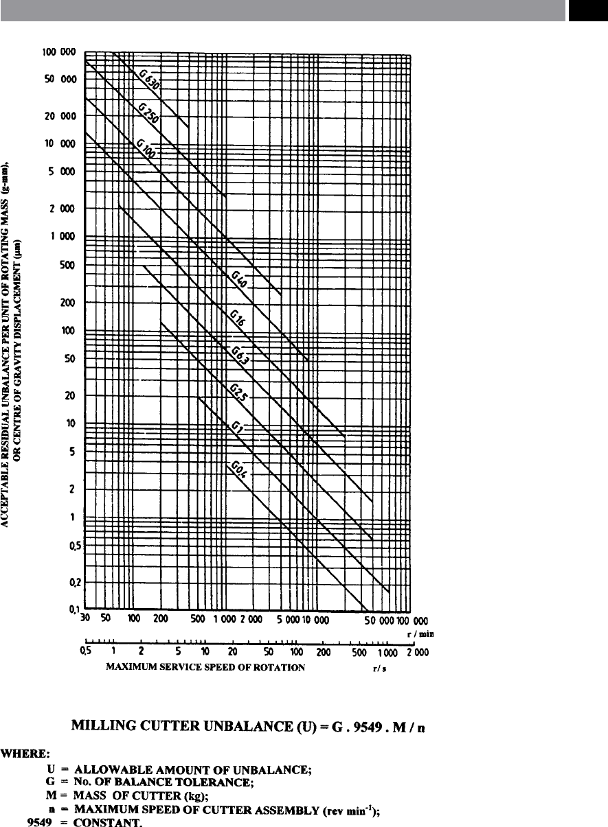
Figure 233. A graph to determine high-speed cutter unbalance ‘U’ (ANSI S2.19–1989).
Machining and Monitoring Strategies 473

designated for the HSM ranges, is by dynamically bal-
ancing the tools in an appropriate machine (Fig. 234a).
us, during tool balancing, the cutter is clamped in
a xture that rotates in very rigidly supported bear-
ings (Fig. 234a). Any unbalance in the rotating cut-
ter is directly measured as centrifugal force, which is
transmitted along with its actual rotational position
to a specially-congured computer. e computer
calculates the amount and location of the material to
be removed from the tool’s body, in order to properly
adjust the mass distribution. is unwanted tool ma-
terial can then be removed, by either drilling holes,
or milling ats (i.e. see Fig. 234b – illustrating that a
small amount of material has been removed – milled –
from its ange and is termed ‘Hard-balancing’). Usu-
ally, ats are preferred for removing larger amounts of
tool material stock, because at high rotational speeds a
tool with a hole can generate a unacceptable ‘whistling
noise’: see Fig. 235 to gain an appreciation of the eect
of these high peripheral speeds, here, a large face-mill
is shown in an HSM automotive application. Since
the ‘balancing operation’ can compromise the tool’s
strength and performance, it is important to establish
where any superuous tool material can be safely re-
moved from on the cutter’s body.
B
alance is a ‘zero-quantity’ , so it is customary to
measure balance in the absence – within acceptable
limits – of unbalance. us, the ‘balance tolerance’ is
the maximum residual unbalance (g-mm) allowed for
a particular tool’s weight and rotational speed. For ex-
ample, the ANSI Standard quality-grades for balance
tolerance range from G0.4 to G6.30, with the lower the
‘G-number’ the closer the balance tolerance. It should
be emphasised, that only when a balanced tool and its
balanced toolholder are balanced together as a com-
plete unit, are they truly dynamically-balanced
27
.
27 ‘Dynamic-balancing’ postscript: the cutting inserts, screws
wedges that are retained in the cutter’s pockets must be se-
curely locked into position. If these small items become de-
tached when HSM, this may cause disastrous consequences
for any operator in the vicinity. erefore, machine tool guard-
ing of more than adequate protection is vital here, to minimise
potential safety hazards to the personnel when in use.
9.6 HSM – Research
Applications
Introduction
Possibly the foremost reason for conducting applied re-
search programmes at various universities and similar
research-based organisations, is to ‘push the boundar-
ies’ of our theoretical and practical understanding of
current, or novel machining concepts. Rather than at-
tempt to give a perhaps less-than-informed account of
what is transpiring at other ‘learned organisations’. It
was decided just to deal with some recent work that
was undertaken by the author, in association with in-
dustrial and academic colleagues, both in the UK and
abroad. As these particular research projects were ei-
ther undertaken, or instigated by the author, oen in
close union with others, mainly concerned with indus-
trial-sponsored doctoral programmes, it was felt that
here at least, some continuity concerning HSM-related
research themes could be achieved.
9.6.1 Ultra-High Speed: Face-Milling
Design and Development
Introduction
In order to achieve a cutting speed of say, 1,000 m
min
–1
, a φ10 mm milling cutter has to rotate at ap-
proximately 32,000 rev min
–1
. In fact, this is quite fea-
sible for smaller diameter cutters, as there are quite a
few of today’s machine tools having HSM spindles that
can exploit these speeds. However, it is worth a sight
digression here, prior to continuing with the theme
concerned with special-purpose UHSM by face-mill-
ing, to ask the pertinent question: ‘What do we mean
by HSM?’ Is it:
•
High rotational speed machining?
•
High cutting speed machining?
•
High feed machining?
•
High speed and feed machining?
•
High productivity machining?
Even these ve potential contenders for what amounts
to HSM, are by no means an exhaustive list, one could
also add more obscure factors such as: the power de-
mand on the spindle; tool assembly balance speeds;
474 Chapter 9
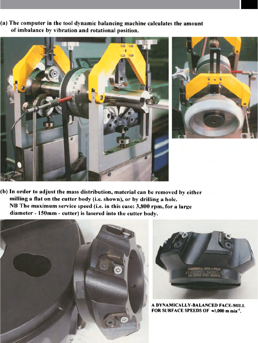
Figure 234. Dynamic dual-plane (i.e. radial and axial) cutter balancing. [Courtesy of Ingersoll].
Machining and Monitoring Strategies 475
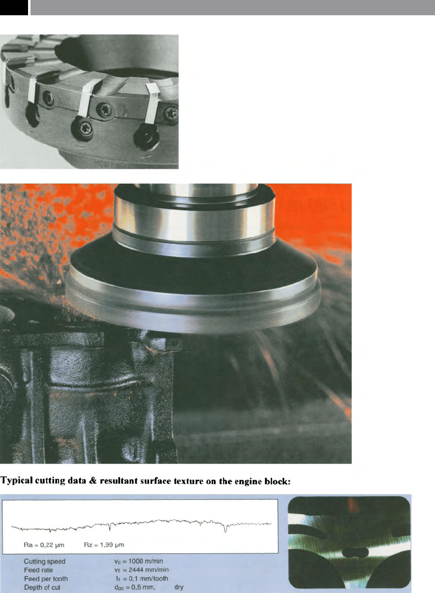
Figure 235. High-speed large diameter face (nish) milling on a grey cast iron engine block. [Courtesy of Sumitomo
Electric Hardmetal Ltd.]
.
476 Chapter 9

the taper size in relation to its rotational speed; thin-
walled machining capability; etc.; the list will grow,
depending upon what we consider to constitute as go-
ing either very fast, or what speed allows us to machine
certain types of part features! Although even here, the
major benets of an ultra-high speed machining strat-
egy are somewhat lost if a ‘working denition’ is not
clearly stated. In this current discussion on the sub-
ject, one measure of HSM could be if the peripheral
speed of the cutter, or workpiece is >1,500 m min
–1
.
Hence, this could represent a base-line for the tran-
sition from conventional to HSM, so for comparison,
as in the case for previously mentioned small diam-
eter milling cutter of φ10 mm, it would need to rotate
>47,750 rev min
–1
, or conversely, a larger face-mill of
say, φ300 mm, would have to rotate at approximately
1,600 rev min
–1
– in order to sustain a peripheral cutter
speed of at least 1,500 m min
–1
. is latter rotational
speed although considerably slower, is a much greater
problem that that presented for the former small diam-
eter cutter. e reasons for this are three-fold: rstly,
has the machine tool got enough spindle power to
achieve the necessary stock removal rates required, or
will it be likely to stall? Secondly, is the spindle taper
tment robust enough to cope with the torque eects
and bending moments imparted during machining?
irdly, will the cutting inserts still be retained at the
high centrifugal forces generated in association with
and exacerbated by the imparted cutting forces? ese
and other lesser important questions and decisions
need to be addressed, if the large diameter face-mill
is to successfully mill across a wide workpiece surface
with any degree of eciency. is former point of the
manner in how workpiece surface stock is removed is
important, for example, two markedly diering ma-
chining strategies could be adopted, such as:
I. Shallow depths of cut combined with rapid tra-
verse rates and small step-overs, utilising smaller
diameter cutters at high peripheral speeds,
II. Deep and wide cuts with a large diameter face-
mill with slower traverse rates, having much
lower rotational speeds.
NB Both machining strategies will remove simi-
lar amounts of part stock!
UHSM: Face-Milling Cutter Design
When designing large diameter face-milling cutter
assemblies for production applications in the UHSM
range, a number of critical features need consideration,
such as: cutter-body material; its weight and rigidity;
taper tment; dual-plane balancing; as well as its aero-
dynamic behaviour – at fast peripheral velocities.
If one attempts to design and develop a large face-
milling cutter with an insert cutting circumference
designed to rotate at 3,000 m min
–1
, which at rst
glance, may not seem that fast. However, if we equate
this cutting speed to that of the same φ10 mm mill-
ing cutter previously mentioned, then this smaller
tool would have to rotate at ≈95,500 rev min
–1
, but
for the larger diameter cutter, it would also require
to be dual-plane balanced
28
. Without dynamic bal-
ancing, the large cutter may be prone to a disastrous
series of vibrational problems, which may ultimately
lead to premature cutter failure – with all its attendant
safety hazards. e cutter design in Fig. 236 for this
applied research programme, was dual-plane balanced
to Standard dened in ISO:1940/1, being to a specic
‘G-number’. is Standard was initially conceived
for the rotational balancing of impellers and similar
high-speed equipment, across a large speed range. e
large face-mills had been dual-plane balanced to G2.5
@ 10,000 rev min
–1
. As mentioned in Section 9.5.1, this
‘G-number’ refers to the maximum tolerable imbal-
ance for the complete tooling assembly, being based
upon the previously described formula (i.e given be-
low again for clarication), resulting in the following
calculations:
Unbalance: U =
� M � G
N
(g-mm)
[or] Force: F = U �
N
�
(N)
Where:
U = allowable unbalance (g-mm);
9549 = a constant;
M = mass, or weight of the total cutter assembly
(kg);
G = pre-selected balance tolerance number from
ISO: 1940/1;
28 ‘Dual-plane balanced cutters’ , are those cutters that have
been dynamically balanced in two planes: having both radial
and axial balance.
Machining and Monitoring Strategies 477

N = maximum rotational speed of tooling assembly
(rev min
–1
);
F =
force (N).
When the above equation for cutter unbalance is
utilised, for these tooling assemblies, utilising the fol-
l
owing values: G = 2.5; M = 4.294; N = 6,000; which
then gave an allowable imbalance U = 17.9 g-mm. is
level of imbalance means that the cutter’s mass can-
not rotationally shi by more than 17.9 g-mm, if it is
to maintain dual-plane balance at a peripheral speed
of at least 3
,000 m min
–1
. In fact, two identical cutter
assemblies were designed and manufactured, hav-
ing a BT40 taper tment – for the vertical machining
centre (i.e. Cincinnati Milacron Sabre 500). In order
to maintain both structural rigidity and integrity,
the complete cutter bodies and their associated ta-
pers were each produced from single stock of EN24T
steel. Aer precision turning and milling the complete
bodies and insert pockets, these cutters were nitride-
hardened
29
to HR
C
52, prior to a ‘very light-grinding’
process and then balancing. e four cutting insert
pockets were equally-spaced (pitched) and the but-
ton-style cemented carbide inserts were: φ1
2 mm by
4mm thick, single-sided and TiN-coated (Stellram:
RPET 1204 DFZ). e insert pocket geometry had a
11° toe angle with a neutral geometry. Button inserts
were selected as they give the strongest shape cutting
geometry available (see Fig. 23), producing an innite
approach angle to the workpiece (see Fig. 83b), thus
minimising impact load at entry to the cut while of-
fering multiple cutting edges – when subsequently
turned in their seatings. As one might expect, insert
security is vitally important, due to the great centrifu-
gal eects and applied cutting forces. Due to the pre-
vious nitride-hardening process, hardened insert seats
were unnecessary, once the retaining screws had been
‘torqued-up’ locking and then sealing them – for se-
29 ‘Nitride-hardening’ , produces a very hard surface with a
soer and tougher matrix. e UHSM cutters were held in a
pressure-tight furnace and heated to between 500-550°C for
some hours in an ammonia gas*, allowing the nitrogen atoms
to diuse into the surface and to form ne stable nitride pre-
cipitates with aluminium constituents, allowing the nitrided-
steel surface to be precipitation- hardened. No subsequent
heat-treatment is necessary.
*Approximately 30% of the ammonia disassociates ( NH
3
→
←
3H+N) and part of the nascent nitrogen is absorbed by the
surface layers of the steel. (Source: Cotrell et al., 1979)
curity. e actual seatings for the inserts had consid-
erable body-support around their periphery, just hav-
ing a working-clearance at the insert’s cutting region.
ese UHSM face-mills were extremely compact, with
the minimum stand-o height from the cutter’s gauge
line (i.e. see Fig. 236), which reduced the eects of the
previously mentioned ‘rigidity rule’.
Due to the relatively large diameter and weight of
these face-mills and the fact that the machining centre
had limited spindle power, these cutters could, if used
a
ppropriately, exploit the ‘mass’ , or ‘ywheel-eect’ of
their weight in conjunction with rotational speed to
‘store inertia’. So, when the spindle power is restricted,
cutters with high mass must be taken up to their de-
sired rotational speed in a progressive manner, other-
wise they are likely to ‘trip’ a ‘spindle over-load’ in the
CNC controller. is steady and progressive increase in
t
he cutter’s rotational speed occurred at 500 rev min
–1
increments – dwelling for several seconds to minimise
inertial power overload, between increases to the de-
sired peripheral speed. Due to the machine tool hav-
i
ng a maximum spindle speed of 6,000 m min
–1
, this
equated to a peripheral cutting speed of 3,000 m min
–1
,
with the face-mill having 0.5 m cutting circumference.
Once the cutter has reached its top speed, it can then
be rapidly progressed (i.e. fed) across the workpiece at
a
rate of 20 m min
–1
. In this case the workpiece ma-
terials were a range of stainless steel alloy testpieces
(Fig. 236). Aer rapidly face-milling these ‘stainless
t
estpieces’ , the cutter’s rotation was decremented in
500 rev min
–1
intervals until stationary. e cutter once
stationary, could have its edge wear (inserts) assused
and workpiece milled surface texture and surface in-
tegrity could be inspected and investigated.
One factor to bear in mind concerning UHSM with
large face-milling cutters being utilised for their ‘in-
e
rtial eect’ , is to design them without driving dogs.
If these ‘dogs’ were tted, not only can they introduce
out-of-balance eects, but tend to signicantly disrupt
the air-ow and introduce alarming and high noise
factors. is aspect of cutter design is important, if
the cutter cannot ‘cleave through the air’ with aerody-
namic eciency, turbulent air ow will result and op-
erational noise becomes excessive. One problem that
these particular cutters did not suer from (i.e despite
the conventional taper-cone angle) – unlike many of
their higher rotational speed counterparts, was ‘spin-
d
le nose swelling’ , which can cause a lack of regis-
ter if the taper tment connection is not of either the
double-, or triple-contact face-and-cone types. One
unexpected aspect of employing such large face-mills
478 Chapter 9
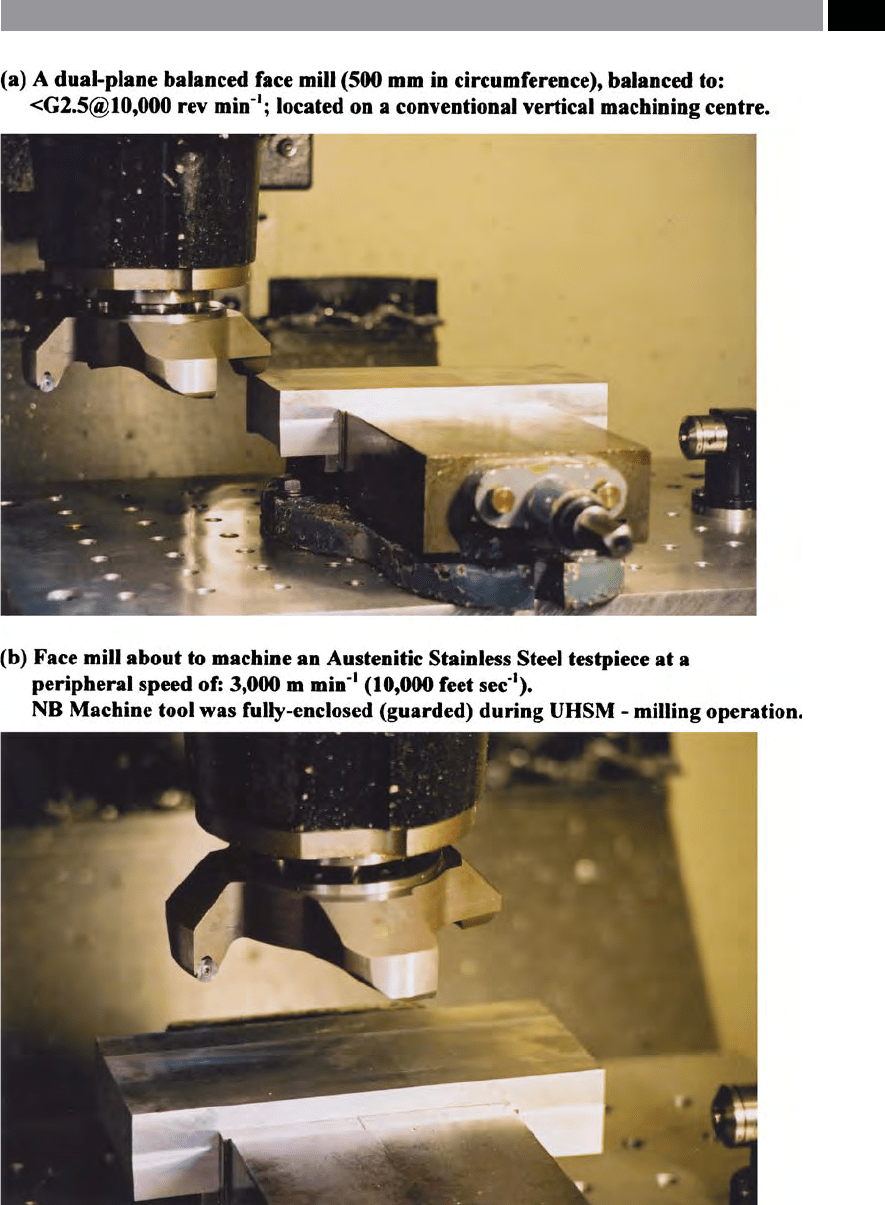
Figure 236. A specially-designed dual-plane (radial and axial) face mill, for ultra-high-speed milling. [Source: Smith,
Wyatt & Hope, 1998]
.
Machining and Monitoring Strategies 479

in UHSM, was found to be due to the very high peri-
pheral speed. A ‘suction-eect’ resulted from the un-
derside clearance of the cutter’s body, created a ‘low-
pressure region’. is ‘virtual vacuum’ here, meant that
conventional-pressure ood coolant application was
not possible, as it simply vaporised to a mist!
UHSM: Cutting Trials
e neutral geometry enabled the cutting inserts to
present a strong cutting edge to these stainless steel
testpieces, enabling an undistorted cut path and ma-
chined cusp to be generated. is insert geometry
feature, allowed the milled surface topography to be
unaected by insert inclination angles. A stringent test
for any cutter is to machine stainless steel by UHSM
(
ie. being least × 10 faster than any work previously
undertaken) and here, tests were conducted on vari-
ous grades (Fig. 236). e subsequent milled surface
analysis showed little in the way of sub-surface plas-
tic deformation – aer UHSM. e surface layers
exhibiting only marginal increases in the vicinity of
the surface when tapered sections were micro-Knoop
‘
foot-printed’ , over these stainless steel’s substrate (i.e.
see Footnotes: 15, Chapter 1; 85, Chapter 7; and Fig.
187c – concerning Knoop indentors usage). Milled
surface topography can be viewed visually and surface
parameters taken by either: 3-Dimensional contact; or
non-contact instruments; but in this case, by utilising
an SEM
30
with its unique ‘Stereo-imaging and topog-
30 ‘Scanning Electron Microscopes’ (SEM’s), operational princi-
ple is relatively simple. In that, at the top of the SEM’s column
an electron gun resides having a tungsten lament held in a
strong electrical eld. is results in the electron gun emitting
electrons (i.e. negatively-charged atomic particles), which ac-
celerate to very high speeds. ese high speed electrons – held
in a vacuum – travel down the column, being inuenced by
lenses lower in the column, which squeeze them together to
form an electron beam of very small diameter. is minute
diameter electron beam is then focussed prior to colliding
with the test specimen in the microscope’s specimen chamber,
now as a diminutive spot. is minuscule spot will then scan
both to the le and to right as well as up and down over the
test surface, the information from which is then brought to a
screen as an image. Prior to this, as the electron beam strikes
the test sample’s surface, many dierent processes occur, such
as: secondary electrons; backscattered electrons; Auger elec-
trons; X-rays; Cathodo-luminescence; etc.; these being emit-
ted, collected and counted, then utilised for further analyses.
raphy soware’ – for 3-D visual assessment coupled to
its height-to-depth proling application.
For the milled testpieces produced from 316-aus-
tenitic stainless steel, subjected to UHSM by this face-
m
ill at 3,000 m min
–1
, the surface topography showed
the inuence of the wear land at produced by the
four φ1
2 mm TiN-coated inserts, although the remain-
der of periodic surface oered little sign of any surface
modication. e 303 stainless steel grade testpieces,
indicating a slight improvement over the former 316
grade. While, 416 martensitic stainless steel testpieces
under identical cutting data generated no appreciable
surface blemishes, with the additional benets of: an
extended cutting insert life; signicant reductions in
both cutting forces and power requirements, over the
303 and 316 stainless steel grades.
9.6.2 Ultra-High Speed:
Turning Operations
Introduction
As has been shown in the previous sections with ref-
erence to HSM by milling, considerable applied and
fundamental research eort has occurred, conversely,
little endeavour has been made regarding high-speed
turning operations. Possibly the major reason for the
lack of interest here into HSM by turning operations,
is because a dierent approach to the workholding is-
sues needs to be taken. In that, on a CNC turning cen-
tre, or lathe, the ‘bursting-pressures’
31
resulting from
signicant centrifugal forces with conventional work-
NB e depth of elds from an SEM are considerably deeper
than that produced by conventional microscopes, allowing
some exacting surface topography analysis to be undertaken.
(Source: Smith et al., 2002)
31 ‘Bursting-pressure’ problems, have been well-known in tra-
ditional turning activities for many years. is aspect of
safe-working practice, was particularly relevant for large cast
iron face-plate work, where a rotational speed limitation is
imposed by a machine tool builder. If this restricted speed is
exceeded, then the cast iron – being poor in terms of tensile
strength, will literally fragment (i.e. ‘burst’), due to the exces-
sive centrifugal forces imposed. While, the problem is not as
severe for chuck and collet work, the lack of gripping-pressure
on the part – at high rotations, will aect the workpiece if long
slender parts supported on one end only are turned – possibly
causing a ‘whipping-eect’ and attendant safety hazard.
480 Chapter 9
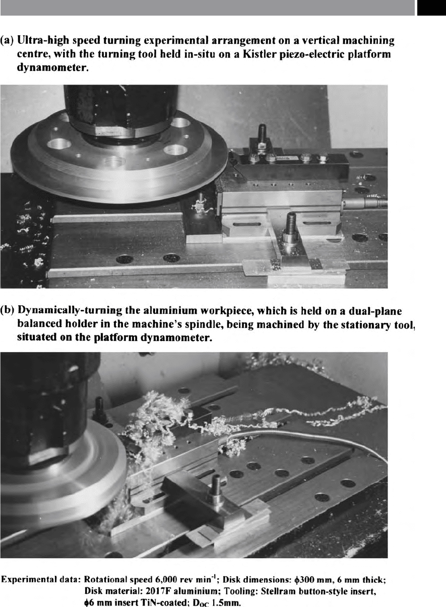
Figure 237. An ultra-high-speed turning operation undertaken on a vertical machining centre. [Source: Smith, Littlefair,
Wyatt & Berry, 2003]
.
Machining and Monitoring Strategies 481

holding: chucks and face-plates; in combination with
a reduction in gripping-force at high rotational speed
is a potential safety hazard. In order to achieve the
d
esired UHSM rotational speeds of >1,500 m min
–1
,
which can be considered as the ‘threshold’ for such a
machining strategy, then the workpiece must be held
in a machining centre spindle – with the tool station-
ary, in a similar manner to vertical turning (i.e. see Fig.
237). Relatively recently in pioneering work by Youse
and Ichida (2000), they utilised rotational speeds up
t
o 15,000 m min
–1
by this technique, showing that the
turned surface texture parameter ‘Ra’ v
alues (i.e see
Section 7.5.1 in Chapter 7) steadily reduced with in-
creases in cutting speed. Moreover, this Japanese ma-
chining study found that the cutting forces remained
relatively constant throughout the test range of: 1,200
t
o 15,000 m min
–1
. is trend of reasonably constant
turning forces with increased speed is contrary to that
normally found for UHSM by milling operations (Ko-
manduri, 1995, et al.), where a signicant reduction
in milling forces results from high cutter rotations,
allowing large length-to-diameter cutter ratios to be
used (Gough et al., 1991).
In any HSM operations, it is essential that the ro-
tational mass of either the workpiece, or cutter – de-
pending upon which is the rotating item, is dynami-
cally balanced, in order to minimise out-of-balance
eects which would otherwise impede both the cutting
process and aect machined surface texture. Ideally,
workpieces, or a cutter should be rigidly held in-situ
during machining and at the very least, be single-plane
balanced.
UHSM: Turning Strategy
Prior to undertaking the UHSM turning operations
(Fig. 237), the machining centre was checked for di-
agnostic errors by a ‘
Telescoping Ballbar’
32
assessment
32 ‘Telescoping Ballbar’ (Fig. 242a), is a powerful instrument for
machine tool error diagnostics. e Ballbar as its name im-
plies, is a ball-ended length transducer (i.e. an LVDT- measur-
ing element, is positioned between the xed and telescoping
balls). is LVDT has a range of ± 0.75 mm with a resolution
of 0.1 µm and accuracy of 1 µm. It is held in kinematic (mag-
netic) seatings between the machine spindle and its base.
Extension bars can increase the radial length up to 300 mm,
covering a large volumetric sweep for the two axes being diag-
nostically monitored. Any kinematic plane can be rotationally
swept by the Ballbar. In operation – from the soware pro-
gram, the machine’s CNC will move the Ballbar to the start
position (i.e. radially oset the required distance for the orien-
set at the radial turning distance in the plane of the
cut (i.e. see the Ballbar conguration in Fig. 242a). A
range of rotational Ballbar speeds were utilised, albeit
at considerably lower peripheral speeds than those
which were employed for the UHSM turning trials.
For this current UHSM work, a machining strategy
was adopted utilising a ‘Variable quasi-pilgrim stepped
arithmetic progression’ (i.e the progression is schemati-
cally depicted in Fig. 238), for the selection of ‘turned
testpiece’ rotational speeds, being based upon the fol-
lowing general progression case criteria:
Sn
1
→ Sn
4
= 2000 + {n
1/
2 [2a
1
+ (n
1
– 1) d
1
]} – 1000
+ {n
2/
2 [2a
2
+ (n
2
– 1) d
2
]} – 500 + {n
3/
2 [2a
3
+
(n
3
– 1) d
3
]} – 250 + {n
4
/2 [2a
4
+ (n
4
– 1) d
4
]} – 125 + …
Sn
n
Where:
a
1
= 2,000, a
2
= 4,000, a
3
= 5,000, a
4
= 5,500;
d
1
= 1,000, d
2
= 500, d
3
= 250, d
4
= 125;
n
1
= 4,000, n
2
= 2,000, n
3
= 1,000, n
4
= 500.
Such an unusual ‘progression’ mathematically de-
scribed above (i.e also being shown schematically in
Fig. 238), enables signicant discrimination of rota-
tional results coupled to data analyses toward the up-
per limit of the UHSM turning process, while giving
‘traceability’ to rotational speeds within the conven-
tional range of the rotational turning process at the
beginning of the turning process.
A special-purpose workholding device – being
d
ual-plane balanced to G2.5 @ 10,000 rev min
–1
, was
tted into the spindle of a vertical machining centre
(Fig. 237). is BT40 tapered workpiece holder was
constructed from one-piece of EN24T steel hardened
by nitriding to >50 HR
C
, weighing ≈2.5 kg with the
aerospace-grade aluminium disk-shaped testpiece in-
tated planes), then it slowly rotates CW for 180° – to pick up
uniform rotational velocity, where it rotates through a further
360° – for polar measurement, nally rotating another 180°
– to slow down. is complete cycle is then repeated CCW.
en polar plots are generated with a diagnostic printout,
which ‘ranks’ these errors, so that they can then be eliminated,
or signicantly reduced, accordingly. is is a speedy, ecient
diagnostic ‘health-check’ of the machine tool errors in the two
measured planes, providing signicant information, which
can be utilised to improve the machine tool’s overall perfor-
mance. (Source: Renishaw Ballbar Training Manual)
NB Typical ‘polar plots’ are shown in Appendix 16, together
with a diagnostic print-out of the results.
482 Chapter 9