Smith G.T. Cutting Tool Technology: Industrial Handbook
Подождите немного. Документ загружается.

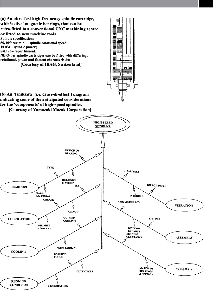
Figure 220. A typical UHSM spindle cardridge listing some of factors aecting such a spindle’s design and its operation.
Machining and Monitoring Strategies 443
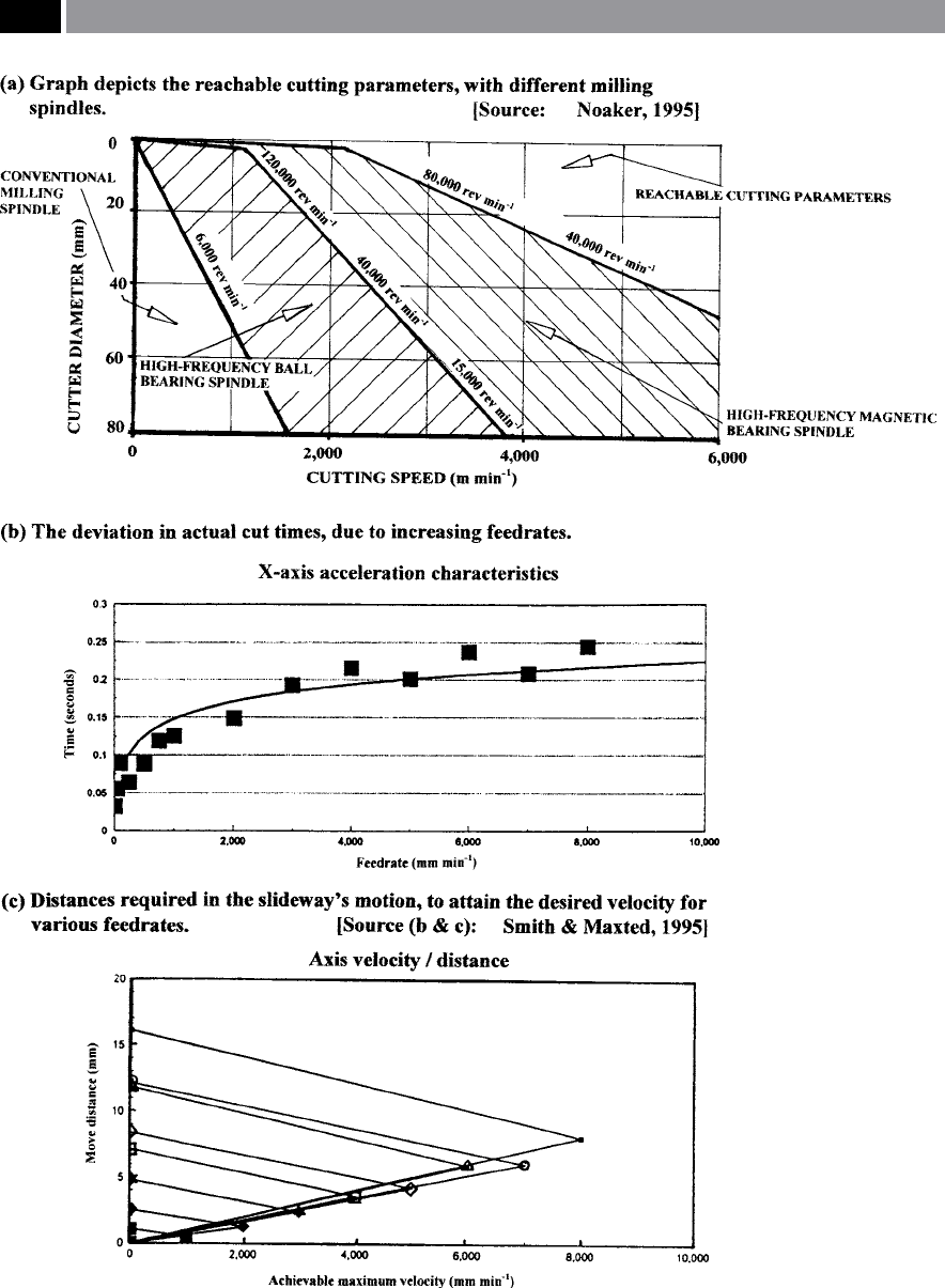
Figure 221. Attainable cutting parameters – with diering milling spindles, plus HSM is aected by the feedrate and distance
to be traversed, prior to the desired velocity being achieved – for conventional slideway motions
.
444 Chapter 9

NB Pneumatic spindles can be rotated at excep-
tional speeds, by virtue of the ‘ideal condition’ of
minimal metal-to-metal contact, although one
serious disadvantage being they suer from a low
power output, or to be more specic – torque.
•
Hybrid spindles (Fig. 214-top) – have been de-
veloped to answer the major drawback to utilising
pneumatic spindles. e hybrid spindle as its name
suggests, is a combination of conventional ball-
bearing and pneumatic spindles. Here, the spindle
design incorporates an aerodynamic thrust bearing
with transversal spiral grooves (Fig. 214-top right)
thereby creating an intense pressure wave prole,
which can withstand up to 300% greater static loads
to that of a conventional aerostatic bearing. A typi-
cal hybrid aerodynamic spindle bearing allows the
assembly to achieve rotational speeds ranging from:
2
0,000 to 40,000 rev min
–1
, with >15.5 kW power at
peak speed.
NB H
ybrid spindle cartridges are signicantly less
expensive than the magnetic ‘active’ spindles, but
more expensive than pneumatic spindle cartridges.
In both of these latter versions, they have a rela-
tively long in-service life, as wear-rates are mini-
mised, but do not have the stock-removal capability
of the former cartridge.
In Figs. 220 and 221a, are shown some of the principal
factors that aect UHSM spindle performance. In Fig.
220, these factors are represented in an Ishikawa (i.e.
‘Cause-and-eect’) diagram. Here, the many of the in-
ter-related eects can be seen, although other factors
can also be added, depending upon the local condi-
tions of usage: cutting data; workpiece material; wet,
dry, or near-dry cutting; together with the machine
tool’s overall condition.
9.2 HSM Dynamics –
Acceleration
and Deceleration
If the HSM spindle cartridges – mentioned above –
are tted to conventional CNC machine tools, or the
more likely low-cost scenario would be to simply t a
m
echanically-driven speed-increaser. en the result
of this HSM spindle tment, will enable high rotational
speeds to be produced, but it leaves the CNC-proces-
sors somewhat compromised in its ability to produce
the desired acceleration and deceleration capabilities.
As a practical example of the problems likely to be
encountered, the graphs produced in Fig. 221b and c,
were drawn from an industrial HSM machining expe-
rience at a precision metrology company’s premises,
using several of the latest vertical machining centres
with the spindle of each machine, being tted with
a mechanically-driven speed-increaser (i.e. see Fig.
243a).
By utilising the inboard CNC clock – having a reso-
lution of 0.0001 seconds, the elapsed times for slide-
way motion over varying distances was established. In
Fig. 221b, an exponential relationship is depicted for
the X-axis, this being a typical situation for the other
axes on the machine tool. By a determination of the
required motional distance to attain specic veloci-
ties, it was possible to illustrate the restrictive nature of
both acceleration and deceleration for small slideway
motions. In Fig. 221c, this illustrates the eect of the
required distances to be executed at various velocities.
From Fig. 221c – by way of an example, if a feedrate of
8
,000 mm min
–1
was utilised, then it would be neces-
sary for a minimum movement of the slideway to be
1
6 mm to momentarily achieve the desired feedrate,
which is typical for a machining centre having an ac-
c
eleration of 1.08 m sec
2
. is physical problem in ac-
tual positioning to the required component’s dimen-
sional feature is not too great a problem for long linear
feeding distances – as the slideway velocity could be
reached, but acceleration and deceleration becomes
exacerbated by the smaller more intricate prismatic
features normally found on the more minute, or
smaller parts oen produced by HSM milling opera-
tions, leading to potential scrappage problems.
From the results of inspection procedures con-
ducted on the HSM over a range of standardised
testpieces, it was concluded that virtually all of the
detrimental dimensional eects introduced by the
HSM milling operations, could be attributed to severe
‘servo-droop’ – more will be mentioned on this subject
shortly. Prior to manufacturing the HSM testpieces,
they were designed on a CAD system and their respec-
tive tool paths were post-processed by the integrated
CAM soware. Hence, with regard to machining cycle
times, they were either calculated by the CAD/CAM,
or were the actual in-cut times – see Table 15. With re-
Machining and Monitoring Strategies 445

gard to these cycle-times for testpiece manufacture, a
signicant improvement accrues when utilising HSM
milling techniques. Although the increase of actual cy-
cle-time from that of the theoretical high-speed CAD/
CAM estimation, can be due to a number of factors
as previously noted by Smith and Hanson (1993). Not
least of which was found in this case, where the CAM
system tended to under-estimate the actual time to
machine a component feature. is time-dierence is
marginally compounded by the ‘servo-droop’ eects.
If the machine tool’s G61 (‘Exact-stop’) mode was
employed, the actual cutting time in general showed
only a marginal increase, over the normal HSM cut-
ting time, although the dynamics of motion tended to
be somewhat jerky in action as the command ensured
it reached its targeted positions. At normal HSM mill-
ing performance, another exacerbating reason for the
increase in cutting time over theoretical, was attribut-
able to the axis acceleration/deceleration parameters
(i.e see Figs. 221b and c). us, these machine tools
basically failed to reach the required slideway accel-
eration/deceleration then maintain these velocities for
about 20% of the total in-cut times, this was for a com-
ponent of somewhat moderate dimensional size and
pocketing intricacy (i.e. the overall testpiece dimen-
sions were approximately: 150 mm in squareness, by
50mm deep).
From the testpiece results, various remarks can
be made concerning the advantages of employing an
HSM strategy over conventional milling practices,
these are:
•
Despite a reduced cut depth, the HSM cycle times
are a 66% improvement over conventional milling
production techniques,
•
Using HSM it will signicantly reduce burr forma-
tion – although not entirely eliminating it, when
compared to that of conventional practice,
•
Distortion of the thin wall features was minimised
by HSM,
•
When employing a speed-increaser (Fig. 243a), its
bearing’s stiness is critically important in order to
obtain an acceptable milled surface texture.
Finally, by utilising even the most elementary form of
HSM approach – using a speed-increaser, highlights
the production advantages to be gained from adopting
this strategy, albeit for limited periods of continuous
cutting time, which normally dictates such ‘increaser’s’
practical usage.
9.2.1 HSM Dynamics – Servo-Lag
Most of today’s CNC machine tools use ‘proportional
servo-systems’ , where the axis velocity is proportional
to the dierence between the actual position and the
command position (Fig. 222a). is ‘error signal’ is
utilised by the system to determine any acceleration/
deceleration necessary as well as the steady-state ve-
locities. As one can visualise from Fig. 222a, the dis-
tance between the actual and commanded positions is
commonly termed ‘servo-lag’. is explanation can be
taken a stage further in Fig. 222b, where the illustra-
tion depicts how a ‘proportional servo-system’ is used
to mill a sloping line. In this example, DX and DY are
the total programmed changes in position on both
the X- and Y-axes, respectively, to go from point ‘A’ to
point ‘B’. Conversely, DX
L
and DY
L
are the amount of
lag on each axis at point ‘C’ along the tool’s path from
‘A’ to ‘B’. Furthermore, in such a system the lag on the
X-axis must be proportional to a similar lag in the Y-
axis, in order to accurately follow the slope of the line.
is aect can be mathematically-represented by the
following relationship:
DX
L
DY
L
=
DX
DY
= Slope of the line
.
In Fig. 222c, we can gain an appreciation of just what
happens when the servo-lag on both axes is not pro-
portional. As the machine tool’s axes travels from point
‘A’ to point ‘B’ , the lag on the X-axis is proportionally
Table 15. A comparison of the theoretical and actual ma-
chining times for the manufacture of testpieces, by various pro-
duction routes
Machining
Method:
Theoretical Cad/
Cam Time:
Actual In-cut
time:
Conventional 3.86 3.71
High-speed 1.26 1.50
High-speed (G61)* 1.16 1.55
NB All times in minutes
* G61 is the ‘Exact-stop’ mode of machine command and, when ac-
tivated, the machine tool will not initialise another movement un-
til the previous axis command has been completed (i.e the target-
point), thus ensuring an accurate and nal slideway positioning.
[Source: Smith and Maxted, 1995]
.
446 Chapter 9
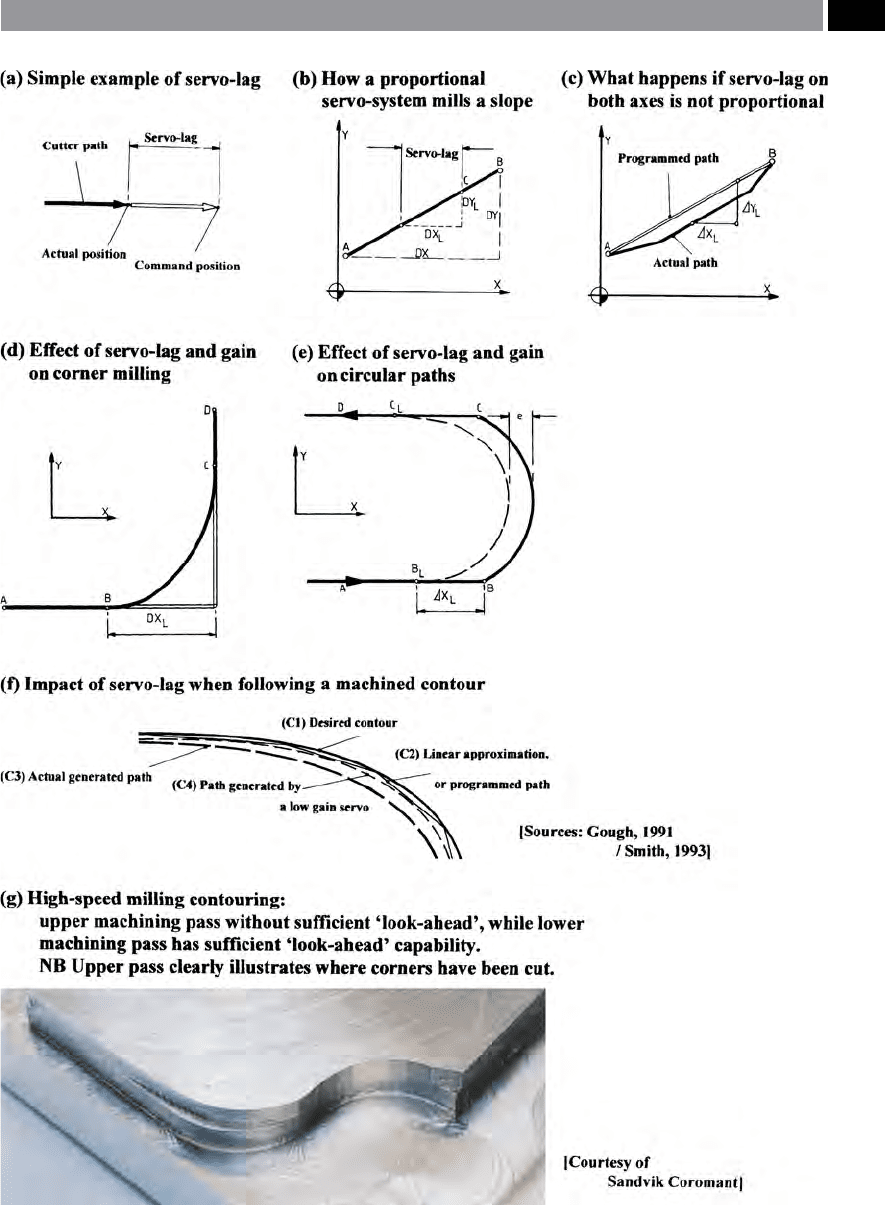
Figure 222. The CNC control problem of servo-lag and its aect on the associated HSM motional kinematics.
Machining and Monitoring Strategies 447

less than the lag on the Y-axis. is error might be the
result of the ‘servo-gains’
12
between the X- and Y-axes
not being properly synchronised. Normally, ‘servo-
gain’ can be expressed in units of: mm min
–1
[i.e. velo-
city / mm (i.e. distance in 0.001)] of lag. us, lag can
be determined using the following relationship:
Lag L (mm) =
Feedrate F
Gain G
=
,
�.
= . mm
.
For example:
If a machine tool’s moving axis is travelling along
its slideway at 2,500 mm min
–1
and the servo has a gain
of 2, the lag will be 1.25 mm, as indicated in the fol-
lowing calculation:
L (mm) =
F
G
=
,
�.
= .mm
.
9.2.2 Effect of Servo-lag
and Gain on Corner Milling
If two axes with correctly matched servo-lags can
move in a straight line from point ‘A’ to point ‘B’ , then
to comprehend the eect of gain, let us consider what
occurs when milling a right-angled corner at a con-
stant feedrate without stopping (Fig. 222d).
Whilst milling the corner from ‘A’ to ‘B’ and the
onward to ‘D’ , the servo develops a steady lag (DX
L
),
until sucient command signals have been generated
to reach point ‘B’. It is at this position that the con-
trol begins to generate commands toward point ‘D’ ,
although the actual slideway has not yet reached point
‘B’ , owing to the servo-lag (DX
L
). At this point the X-
axis will begin to decelerate and, simultaneously, the
Y-axis begins to accelerate, that is the velocity is pro-
portional to the distance between the command signal
and the actual position. Acceleration factors aect the
slideway motions producing the result that the dis-
tance from ‘B’ to ‘C’ is always greater than DX
L
. Fur-
thermore, this curved path is not a circular arc, but an
exponential curve, with the amount of variance from
the sharp right-angled corner being dependent on the
12 ‘Gain’ or to be more specic: ‘servo-gain’ , in this instance, is
a measure of the servo’s responsiveness. us, the higher the
gain, the lower the lag.
magnitude of servo-lag
13
, which itself depends upon
the aect of feedrate and gain – according to the previ-
ous formula.
9.2.3 Effect of Servo-Lag and Gain
Whilst Generating Circular Paths
For one to fully understand just what happens when
milling complex contours, it will be helpful to consider
the simple case of a milled path where two straight
lines are joined by a semi-circle (Fig. 222e). In this
situation, the milling operation occurs at a constant
feedrate moving from point ‘A’ in a straight line until
the command dimension reaches point ‘B’ . However,
at this point, because of the eect of servo-lag, the axis
motion will have only reached point ‘B
L
’. erefore, as
the control command is moving forward at a constant
rate, it begins to generate commands toward point ‘C’.
is action results in the axis motion beginning to
move away from the desired path at point ‘B
L
’. e dot-
ted line depicted in Fig. 222e, shows the actual path
taken by the cutter and as one can visually observe,
from points ‘B
L
’ to ‘C
L
’ , the deviation from the desired
path is shown as ‘e’.
In this example, the magnitude of ‘e’ is determined
as a function of the: feedrate; gain; plus the desired
radius. When the radius error approaches the pro-
grammed radius, the resulting machined prole ap-
pears distorted and is hence, impracticable. Speci-
cally, if one needed to mill a 25 mm radius at a feedrate
of 2,500 mm min
–1
with a machine tool gain being:
25 mm/min/0.001, then the error generated would
be approximately 0.125 mm, equally, if the gain was
increased to 100 mm/min/0.001, the maximum er
-
ror ‘e’ will be considerably reduced to approximately
0.008 mm.
A machined curve is an approximation on CNC
machine tools, in that the prole is constructed from
a series of short connected segments, or chords. e
controlling factor on the length of such segments is
the deviation between the centrepoint of any chord
13 ‘Servo-lag’ , is sometimes referred to in the literature as:
‘Servo-droop’ – due to its ‘rounding-eect’ at the corners, this
being particularly prevalent when fast feedrates are selected,
creating fast tool path velocities, particularly when normally
undertaking high-speed milling operations.
448 Chapter 9

and a point at right angles on the programmed curve.
e linear distance between these two points is usually
termed the ‘maximum allowable chordal deviation’ and
is a function of the CNC controller’s executive soware.
So, the resultant machined curve is a combination of
the chordal deviation and the servo-lag for a particu-
lar machine tool. To illustrate this condition, Fig. 220f
shows the culmination of servo-lag when following
a contour, with the curve ‘C1’ being the desired con-
tour, ‘C2’ a linear approximation (i.e. the programmed
path), ‘C3’ is the actual generated path resulting from
servo-lag utilising a high gain servo and nally, ‘C4’
being the path generated by a low gain servo. rough
servo-lag, a smoothing of any contour occurs owing to
the lagged cutter path, this causes severe contour prob-
lems with respect to part accuracy and precision for
the simple arc geometry depicted in Fig. 222e. Clearly
then, servo-lag and gain promote a variety of eects
on complex shapes, depending upon their geometry
and tolerance, with these errors becoming still more
complicated when one considers three-dimensional
milling contouring. In many circumstances the cutting
of three-dimensional proles may necessitate utilising
four, or more axes with either one, or two of them be-
ing rotary axes being necessary to create the required
tool paths to produce the component. e servo-lag
and gain on all axes must be considered when manu-
facturing complex part geometries. Regardless of the
workpiece’s geometry, or the number of axes utilised,
there is one factor that should be emphasised concern-
ing potential errors created by servo-lag. If servo-lag
is extremely large, then this ‘lag’ can easily exceed the
positioning errors in the machine tool’s basic speci-
cations.
9.2.4 CNC Processing Speed
Possibly the main factor limiting contouring speed is
the CNC’s inherent processing speed, with each pro-
grammed-block
14
generated for every axis having to
14 ‘Programmed blocks’ , these are basically the ‘G-’ and ‘M-’
and ‘Auxiliary-codes’ which make up each individual block’s
line, with successive blocks in a logical sequence containing
the whole CNC program. Generally speaking, the smaller the
number of blocks – for the successful production machining
of the part, the more ecient and rened has been the pro-
gramming. (Smith et al., 1993)
be read, interpreted, the activated to obtain dynamic
slideway motions. is CNC exercise is usually re-
ferred to as the ‘block processing time’. e maximum
allocated time for block processing of information is
dependent on the length of slideway stroke (i.e. chord
length) and its associated feedrate. It is possible to cal-
culate the maximum block processing time (T
b
), as
follows:
T
b
=
Maximum stroke length
Feedrate
For example: if we require a prole’s chord length (i.e.
stroke length) of 0.50 mm, in order to maintain con-
touring accuracy whist milling at 3,000 mm min
–1
, or
50 mm s
–1
, with a maximum block processing time,
then this ‘time’ should be less than:
T
b
=
.
, �
=
.
= . s, or ms
Many CNC’s have block processing times typically
within the range of 30 to 60 ms, as can be seen from
the above example, the CNC program would suer
from ‘data starvation’ , whilst the controller attempts to
catch up on its data processing. Such ‘starvation’ would
cause hesitation in the slide motions, slowing down
the cutting time and leaving ‘dwell marks’
15
on the ma-
chined workpiece’s surface. Since this ‘data starvation’
eect is unacceptable, a lower feedrate must now be
programmed to overcome the problem and as a re-
sult, the cycle-time increases. In the above example,
if an older CNC was tted to the machine tool with
the controller’s block processing time being 60 ms, the
cut would have taken six times longer to generate the
prole, than a more modern CNC controller having a
processor capable of 10 ms.
So that we can fully-comprehend the CNC process-
ing speed problem, let us now consider two widely dif-
fering machining applications:
1. Complex three-dimensional milling of a hob – to
manufacture a die utilised in the production of in-
tricate and expensive military metal buttons. Such
15 ‘Dwell marks’ , here are the result of an ‘untimed delay’ in the
program’s execution, created in this instance, by data starva-
tion (i.e. block processing speed was simply not fast enough).
ese untimely delays in the activation of programming
blocks cause the rotating cutting tool to rest and press against
machined surface and thus, generate minute ‘gouging-eects’
in the surface. (Source: Seames, 1990; Smith, 1993)
Machining and Monitoring Strategies 449

a hob will more than likely have very ne detailed
work on its surface, perhaps with radii as small as
0
.25 mm, requiring a tool tip radius of 0.025 mm.
In order to machine the button’s elaborate features
with such a small milling cutter, the spindle speeds
m
ight need to reach 40,000 rev min
–1
, utilising a
feed per revolution of 0.008 mm, giving a feedrate of
320 mm min
–1
. Many production engineers would
not consider this as an example of high-speed mill-
ing, but let us look more closely at this particular
machining problem. If the controller has a servo-
g
ain of 4, with a feedrate of 320 mm min
–1
, this
means that the servo-lag would be 0.75 mm min
–1
,
which is consistent with milling radii of 0.25 mm.
However, if the servo-gain was 1, this would cause
a
servo-lag of 0.320 mm min
–1
and in this case, it
obviously could not machine that button’s intri-
cate detailing. In such circumstances, it would be
necessary to appreciably reduce the feedrate to
s
ay, 75 mm min
–1
to generate the button’s contours,
leading to the cycle-time increasing by 400%. Let
us also now consider the impact of block process-
ing time under these conditions. To mill a radius as
s
mall as 0.25 mm, we would need to produce linear
stroke lengths of just 0.075 mm – to reproduce ac-
ceptable button detailing. is intricate contouring
w
ork requires a block processing time of 15 ms. If
the CNC controller has a block processing time
o
f just 60 ms, then the feedrate must be limited to
7
5 mm run
–1
which again, increases milling time by
a factor of four.
2. E
CM pattern electrode for a Turbine fan (i.e large
aluminium casting) – here, the electrode’s geom-
etry has very gentle three-dimensional curves. In
this situation the chosen CNC machine tool’s mill-
i
ng spindle has a 250,000 mm min
–1
capability, cou-
pled to adequate power to cut at a feed of 0.25 mm
rev
–1
. is production requirement produces a feed-
rate of 62,500 mm min
–1
(i.e. being the product of:
250,000 x 0.25) would be possible. For accuracy
and precision, a chordal deviation (C
d
) of 0.005 mm
would indicate a stroke length of 0.75 mm – if the
minimum radius of curvature for the Turbine fan’s
g
eometry was 25 mm. Assuming that the servo-
gain of 1 was available, then we would obtain errors
a
s large as 0.125 mm and with such errors, the ma-
chine tool would not produce an acceptable part.
F
urther, at 62,500 mm min
–1
, if the block process-
ing time (T
b
) was 60 ms, this ‘timing’ would require
stroke lengths of 2.5 mm instead of the 0.75 mm we
needed for the required accuracy and precision.
erefore, in order to eliminate the eects of low
gain, or slow processing time, it is necessary to de-
press the feedrate, resulting in the cutting time be-
ing increased up to 400%.
When considering these two practical examples from
a metaphorical sense, the former method can be com-
pared to that of racing a go-kart on a small tight track,
while the latter method is similar to a highly tuned
sports car racing on a longer and smoother track. e
g
o-kart may only reach speed a of 30 km h
–1
, whereas
the sports car may hit speeds of >200 km h
–1
. e
corner forces and reaction times are similar for both
methods, even though the speeds are vastly dierent.
Looked at from yet another viewpoint, we can say that
the frequency of response of both the drive and car,
that is their servo-gain and processing time, are very
s
imilar in both examples even though the speeds (feed-
rates) are radically dierent.
In the day-to-day production environment, the du-
plication of specic and precise contours is the end re-
sult of a combination of many inter-related factors. As
the number of machine tool axes required to produce
sculptured part surfaces increases, the diculty of ob-
taining the desired prole also becomes proportion-
ally problematic. So, machine tools that would nor-
mally produce excellent general-purpose machining
work, may not be either accurate, nor ecient enough
to manufacture complex part contouring geometries.
at is, unless their CNC processors can achieve block
p
rocessing speeds of <10 ms, with servo-system gains
of up to 4, having sucient ‘look-ahead’
16
capabilities
(i.e. see Fig. 222g) that are required, for any realistic
and practical HSM applications.
16 ‘Look-ahead’ facilities, are when the controller has the abil-
ity to look-ahead through the following sequenced program-
ming blocks* to determine successive motions and actions
– an important feature for any HSM applications. Many of
today’s sophisticated CNC controllers can look-ahead through
a considerable number of these blocks, thereby prompting the
controller’s response, prior to undertaking any command exe-
cutions. *A ‘Block’ can be dened as: A set of words, characters,
digits or other elements handled as a unit – hence, the term
‘block’ – which creates a sequence of lines of a computer pro-
gramming language, that can then be activated upon by the
machine tool‘s CNC controller, producing the necessary pro-
grammed-actions. (Source: Smith et al., 1993)
450 Chapter 9

9.3 HSM – with Non-
Orthogonal Machine
Tools and Robots
Variax/Hexapod – Design Concept
Non-orthogonal machine tools such as the one simu-
lated, designed and developed for HSM applications
is typically illustrated in various ways in Figs. 223 to
225: utilising ‘virtual’ six axes kinematics (i.e. namely:
X-, Y-, Z-, A-, B- and C-axes), therefore these axes
operate without having any ‘true’ slideways. is par-
ticular kinematic concept has actuators that cross each
other forming X’s instead of meeting at apexes to form
triangles, as they occur in aircra ight simulators,
which uses conceptually similar mechanisms – known
as Stewart platforms, these congurations being a
form of ‘parallel kinematic link mechanism’ (Fig. 223).
To develop this new concept for a machine tool, the
manufacturer utilised computer-aided technology
which played a pivotal role in creating the structural
design (Fig. 223). In particular, the application of a
totally three-dimensional design environment was
employed, utilising both nite element analysis (FEA)
in conjunction with kinematic analyses. However, the
‘Variax’ design uses a range of uncomplicated, or stan-
dard mechanical components in its design. While new
forms of motion actuators were discarded in favour of
conventional and well-proven ballscrew technology,
with its accompanying motor and drive machinery.
Even the gimbals that secure the legs at the base and
the spindle carrier, are relatively simple devices.
With the design of such a high thrust machine, a
signicant problem to overcome was the connection
of the spindle to the six legs (Fig. 223a). e answer
to the connection problem was a simple space frame
design, allowing all the forces to be either in tension,
or compression along the structural elements – similar
to a bridge design. If one compared this ‘Variax design’
with that of a ‘plate-type design’ to secure the spindle
to the legs, then the former space frame concept im-
proves the mass-to-stiness ratio by 275%. While an-
other key development problem to be overcome was
that of how a spindle supported and driven by six
axes kinematically moves in space, moreover, was it
even mathematically possible to control the motional
members? For example and by way of illustration of
this complex mathematical/control problem: a simple
‘X-axis’ linear kinematic translation requires all six
legs to simultaneously move, but each leg will move at
dierent speeds, either accelerating, or decelerating at
dierent rates through the whole ‘linear movement’ –
requiring very complex multi-axes mathematical solu-
tions to achieve this action. By employing a system of
novel mathematical transformation runs in real-time
by the CNC’s multi-processor this mathematical trans-
lation action was achieved, but from a programmer’s
viewpoint, conventional ‘word-address format’
17
of
programming knowledge was all that was needed to
successful operate the machine tool.
Non-Or thogonal Versus Orthogonal
Machine Tool Designs
e ‘Variax’s’ machine capabilities and benets dif-
fer signicantly from those found on conventional
slideway-based orthogonal machine tools. So, on an
orthogonal machine the slideways must be perfectly
straight, parallel and at 90° to each other. On these
machines, an axis must have accuracy and precision
control along the slideway having linear and rotary
degrees of freedom carefully managed by the ground
way being scraped to minimise any impending errors/
uncertainties. As mentioned earlier, these orthogonal
axes have kinematically 21 degrees of freedom, with:
linear motion; rotational – i.e. yaw, pitch and roll; plus
17 ‘Word-address format’ of CNC programming, can be consid-
ered as: A system of coding instructions whereby each word in
a block is addressed by using one, or more alphabetic characters
identifying the meaning of the word. [Source: Valentino and
Goldenberg, et al. 2000]
For example, some typical ‘G- and M-codes’ are:
G00 – rapid movement/ traverse of the tool (modal);
G01 – linear interpolation (ie. tool moved at a prescribed fee-
drate) (modal);
G02 – circular interpolation clockwise – CW (modal);
G03 – circular interpolation counter clockwise – CCW
(modal);
G04 – programmed dwell (*non-modal);
G40 – Cancel cutter diameter compensation (modal);
G41 – tool diameter cutter compensation (i.e. radial-oset) on
le-hand side of workpiece (modal);
G42 – tool diameter cutter compensation (i.e. radial-oset) on
right-hand side of workpiece (modal);
M00 – Program stop;
M02 – End of program;
M03 – spindle on (CW);
M04 – spindle on (CCW).
NB Many more codes/auxiliary functions exist, utilised in
‘word-address format’ programs.*Non–modal commands are
only active in that actual block. [Source, Smith et al., 1993]
Machining and Monitoring Strategies 451
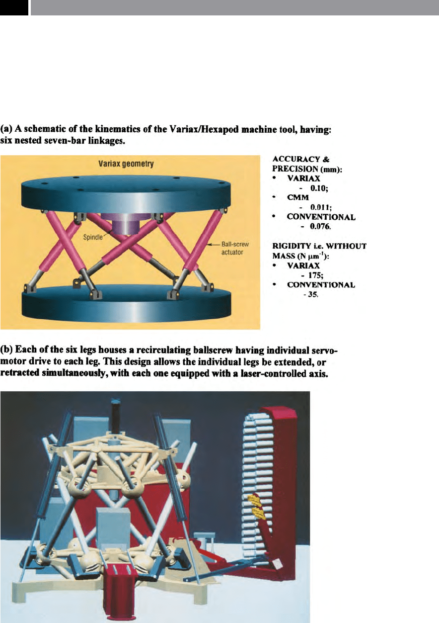
Figure 223. Basic kinematics of the non-orthogonal machine tool, with a simulated rendition of the es-
sential elements of the machine’s structure. [Courtesy of Giddings & Lewis]
.
squareness errors to be considered, if the machine tool
is to perform within its intended specication. In ef-
fect, with an orthogonal machine tool three axes are
controlled (i.e. the X-, Y- and Z-axes), and the rota-
tional and squareness parameters must be ‘perfect’.
us, these errors/uncertainties can be established by
laser-calibration, then compensated for up to a certain
extent to create and ‘stable machine’. If for example,
one considers the worst case scenario for a machine
tool conguration, namely that of a horizontal ma-
chining centre. Here, if we just deal with one axis,
then the spindle travels up and down the column’s
452 Chapter 9