Smith G.T. Cutting Tool Technology: Industrial Handbook
Подождите немного. Документ загружается.

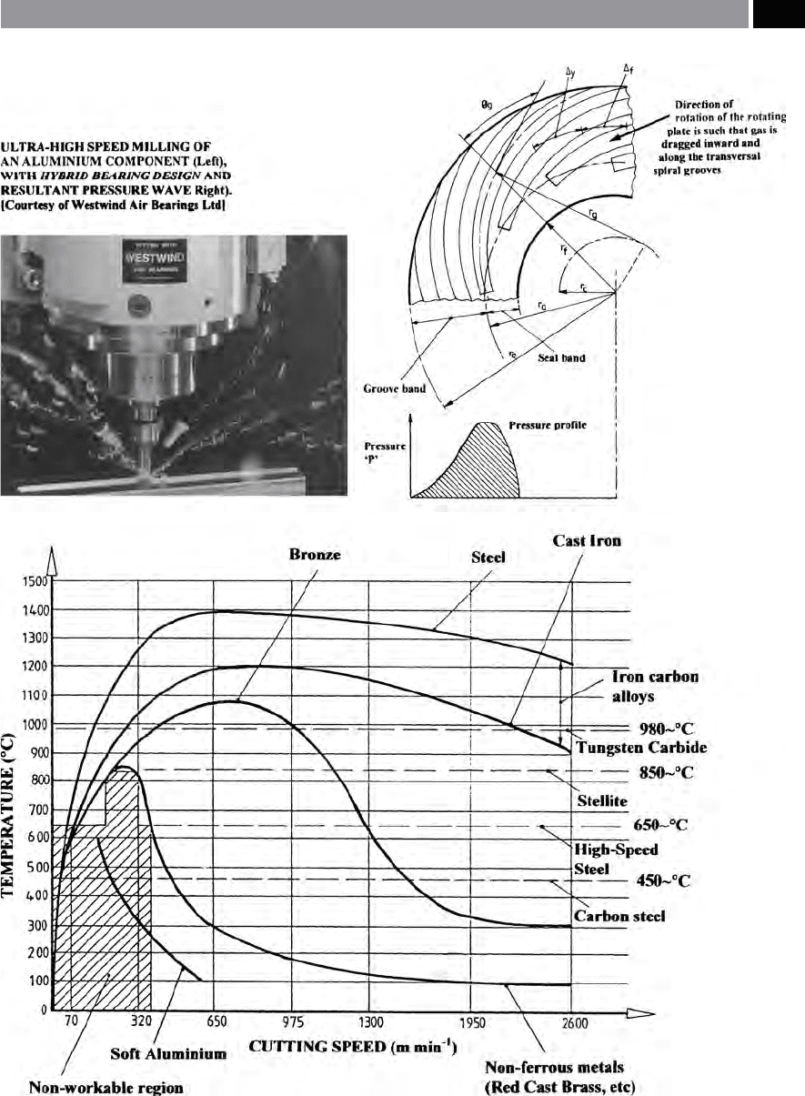
Figure 214. Graphical relationship of high speed machining of metals – according to Salomon’s machining trials. [Source:
Salomon, circa 1920’s–30’s]
.
Machining and Monitoring Strategies 433

did not indicate how such ballistic speeds might be in-
corporated into a production application, also, an ana-
lytical model of this high-rate cutting phenomenon
was not developed.
In the 1960’s and early 1970’s some consolidation
of important machining data occurred, with notable
work on UHSM cutting mechanisms, etc., that oc-
curred in various countries being led principally by
the USA in work from: Coldwell and Quackenbush
(1962), plus Recht (1964); Okushima et al. (1966) and
Tanaka et al. (1967) in Japan; Fenton and Oxley (1967)
in the United Kingdom; and Arndt (1972) in Australia.
However, although there was a general increase global
research activity during this period, it was somewhat
disparate and mainly of a fundamental, rather than ap-
plied nature.
e third period of HSM development was insti-
gated in the mid-to-late 1970’s by the United States
Navy, in conjunction with the Lockheed Missiles and
Space Company, Inc., who contracted a series of ma-
chinability studies on marine propellers
3
. Here, the
Lockheed group headed-up by King, were mainly
concerned with the feasibility of utilising HSM in a
production environment, primarily for aerospace alu-
minium alloys, then later, working on nickel-alumin-
ium-bronze. King’s team at Lockheed, demonstrated
that it was economically feasible to introduce ‘high-
speed-machining’ procedures into the production en-
vironment, thereby realising the signicant improve-
ments in productivity with this HSM application. Such
applied research work, promoted signicant activity
and interest in this HSM eld and, it soon became
clear that attention needed to be focussed for all of the
subsequent small and diverse research programmes.
3 ‘Marine propeller manufacture’ , whether from a wrought-
solid material, or nishing-o a casting, is probably the most
dicult and complex multi-axes milling operation that can
be undertaken – due to the fact that the propeller surfaces
to be machined are continuously changing their geometry as
they are essentially parabolically-curved. Invariably, the part
geometry is typied by say, the NACA/NASA Standard 16-021
‘aerofoil cross-sectional prole’ , which for high-performance
propellers are exacerbated by normally having both consider-
able rake and skew to each blade – creating an exceedingly
complex geometry and llet where the boss and blades inter-
sect*.
* See: Smith and Booth (1993) paper – in the references,
which goes some way to explain the propeller manufacturing
subject, and for more detailed multi-axes machining and for
subsequent machined propeller measurement information.
Finally, in these formative years of experimental
work into HSM, the fourth period of development be-
gan in 1979, when the USAF awarded a contract to the
General Electric Company, in this instance, to provide
a scientic basis for faster metal removal via HSM and
Laser-assisted machining
4
. A further contract by the
USAF in 1980, was also awarded to ‘General Electric’–
the group also being headed by Flom (1980). With this
new HSM contract, also being granted to Flom’s group,
with the objective to evaluate the production implica-
tions of the previous contract. Both of these contracts
being supported by a consortium of industrial com-
panies and selected universities in the USA – initiat-
ing the fourth HSM period of development. At around
this time (i.e. in the late 1970’s), the introduction of
computer numerical control (CNC) systems occurred
and as a result, they were immediately being tted to
a new range of machine tools, signicantly enhanc-
ing both their usability and programming capabilities,
acting as a catalyst in the development of HSM strate-
gies. As these CNC controllers became more sophis-
ticated and processing speeds substantially increased,
this meant that the potential for HSM could now be
fully realised. In recent years, HSM machine tools are
just about everywhere in machine shops around the
world, where ever there is a need for highly produc-
tive part production with very fast cycle times. Obvi-
ously, on HSM machines as the spindle speeds have
increased in association with both tool and their re-
spective workpiece materials (i.e. see Fig. 215), this has
meant that there are now considerable design implica-
tions on these machine tools, these topics will now be
succinctly discussed.
9.1.1 HSM Machine Tool Design
Considerations
Prior to a discussion concerning machine tool design
factors that must be addressed, before to fully-imple-
menting this HSM technology, one might ask the
question: ‘Why do we need to rotate cutters at such high
spindle speeds?’ ere are a number of advantages that
can accrue from adopting such a progressive produc-
4 USAF contract to the General Electric Company in 1979, was:
F 33615-79-C-5119 – for a feasibility study into the fast metal
removal operations by HSM and Laser-assisted machining.
434 Chapter 9
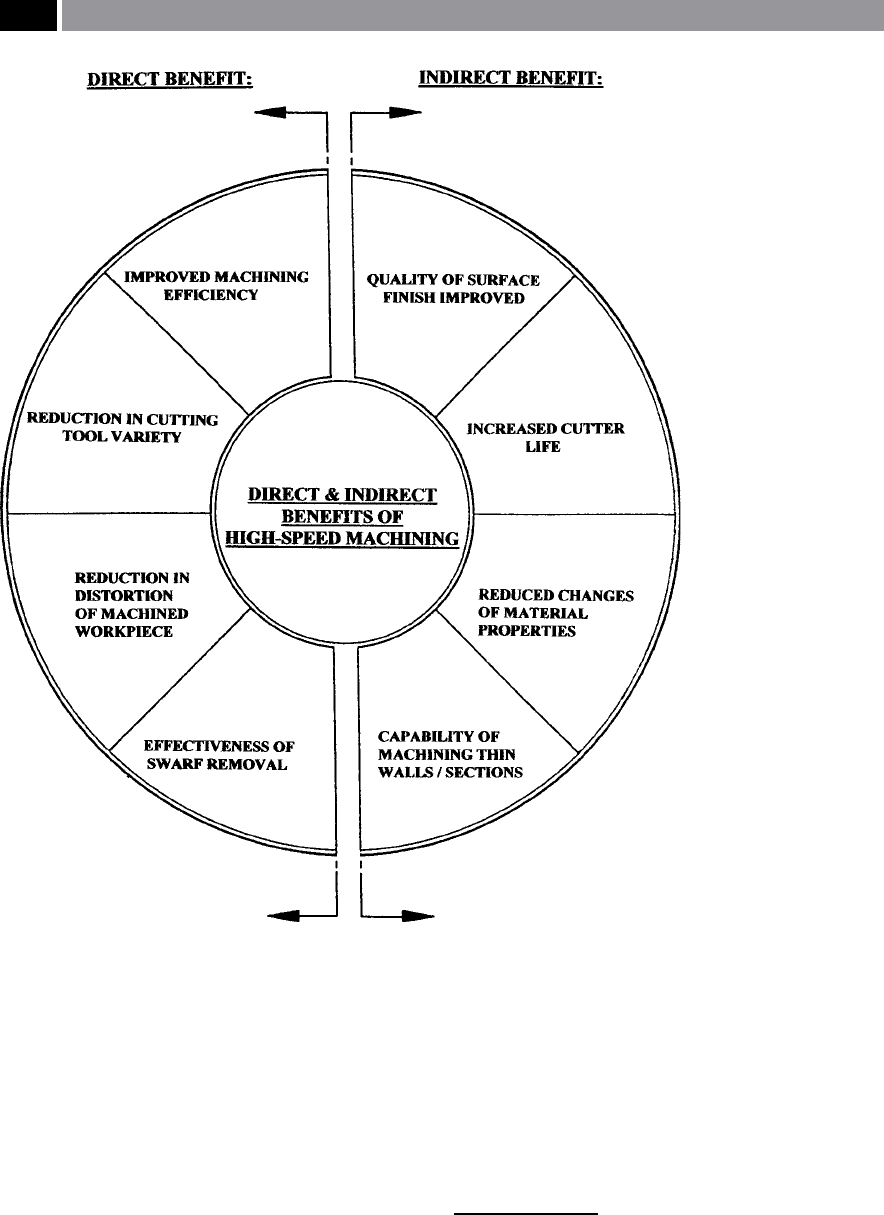
tion machining strategy (i.e. see Fig. 216) and, they
can be succinctly summarised as follows:
•
Direct benets
–
improved machining eciency,
–
reduction in cutting tool varieties,
–
reduction in distortion of workpiece,
–
eectiveness of swarf removal.
•
Indirect benets
–
quality of nish improved,
–
increased cutter life,
–
reduced changes in material properties,
–
capability of machining thin walls/sections.
ese production improvements are by no means all
that occur, as invariably, due to the superior machined
surface texture, the nal part surface may not need
to be deburred – a signicant real saving on complex
component geometries. Moreover, by employing an
HSM strategy, more simple xturing can be utilised, as
the actual tool forces are signicantly lessened.
It is an established fact that with higher rotational
cutter speeds the resulting cutting forces and tool
push-o are considerably reduced. In order to benet
from these improved cutting practices, the machine
tool’s axes must have both faster acceleration and de-
celeration – see Fig. 221, more will be mentioned con-
cerning these important dynamic aspects of a machine
tool’s operational performance shortly. Many of today’s
conventional and HSM machine tools, are based upon
a modular design concepts (Fig. 217a). is modular
design philosophy, allows the machine tool builder
the opportunity to standardise certain features over
a range of machine tools. Such practice benets the
manufacturer and consumer alike, by reducing design
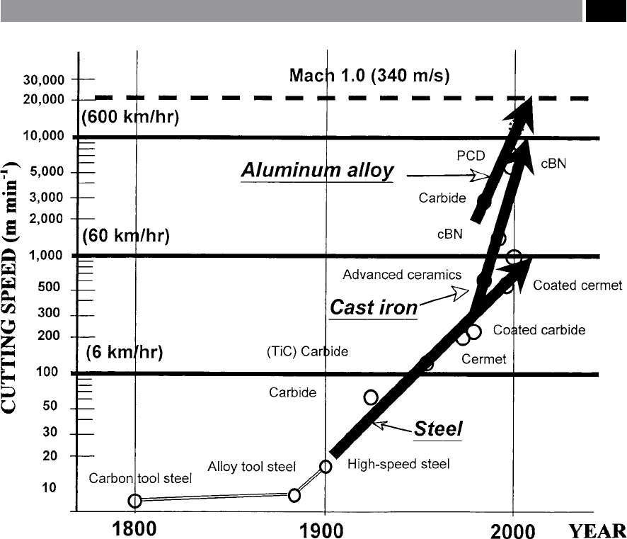
Figure 215. The chronological development of cutting tool material introductions, which had an inuence on high-speed cut-
ting trends. [Courtesy of Yamazaki Mazak Corporation]
.
Machining and Monitoring Strategies 435
and development costs, while minimising the custom-
er’s purchasing costs, yet still allowing more attention
to be given to the detailed design of each ‘module’ in
the machine. So, an identical column, or table may be
common to a variety of machines and this trend can
oen be seen across a whole product range of ma-
chine tools. Not only are the major castings, or large
fabrications manufactured by employing modular
concepts, but this design philosophy also allows any
other smaller components to be standardised and t-
ted accordingly. Such as: the recirculating ballscrews;
servo-motors; linear scales – if tted; etc.; plus other
standardised items to be built into the constructed
machine tool ranges.
In order to minimise ‘
stick-slip’
5
in the slideway mo-
tions on heavy moving cast and fabricated members –
5 ‘Stick-slip’ or ‘Stiction’ , is the jerky-motion between sliding
members due to the formation and destruction of junctions
[due to localised pressure-eects]. (Kalpakjian, 1984)
Figure 216. Diagram illustrating the main benets to be gained from adopting a high-speed ma-
chining strategy. [Source: Smith, CNC Machining Technology, 1993]
.
436 Chapter 9

thereby giving faster response to CNC commands, ‘Ty-
choways’ (i.e see Fig. 217b), or similar mechanical aids
are usually strategically situated at set positions along
each hardened way of the machine tool’s orthogonal
axes (i.e normally at the ‘
Airy-points’
6
).
6 ‘Airy-points’ , are associated with any ‘elastic body’ that is
subject to load, where will undergo elastic deformation. e
magnitude of this deformation depends upon the extent of
the: load; contact area; plus the mechanical properties of the
contacting materials. Hence, if the prospective body is not
correctly supported, it will be subject to elastic deformation
– under its own weight. is problem was considered in 1856
by Sir G.B. Airy (Astronomer Royal) – who was interested in
minimising the elastic deections that arose when attempt-
ing to support and reduce the sagging in long focal length
refracting telescopes. Airy showed that by positioning these
two supports at prescribed distances, they could minimise
any potential error – when equated to the overall length of the
‘elastic member’ (i.e. in the length of the telescope). He found
that two conditions occur, one being for ‘line-standards’ – to
bring the ends square for measurement and calibration, and
secondly, relating to machine tools and many metrological
applications, where the ‘Points of minimum deection’ were
more appropriate, as follows:
Distance between each support = 0.554L
Using conventional recirculating ballsrews (Fig.
217c) for HSM applications is possible up to 100 m
min
–1
– in certain applications. Aer these linear velo-
cities have been reached and it is necessary to reverse
the axis direction, this can create ‘ballscrew wind-up’
problems. is ballscrew twisting, is despite the fact
that the ballscrew is very sti of the order >2,000
N µ
m
–1
, so if greater kinematic and dynamic perfor-
mance is required, then it might be necessary to utilise
linear-motor drives. A tabulated table for suitable
comparisons of the various types of motional drive
systems available today, is presented in Table 14.
It has been widely-reported that either a high-qual-
ity lead-, or ball-screw having rotary encoders, will
have a unidirectional repeatability to within 6-to-
Where: L = overall length of the ‘elastic member’. (Galyer and
Shotbolt et al., 1990)
Example: If a machine tool’s structural moving member is
1,000 mm in length and it is situated on a much longer ‘bed-
way’ , then the ‘Tychoways’ should (ideally) be symmerically-
positioned (i.e. xed to the moving member) at a distance of
554 mm apart – in order to obtain the minimum of elastic dis-
tortion as it moves backward and forward along the hardened
bedway.
Table 14. Comparison of dierent drive systems for machine tools
CONTRIBUTIONS: Leadscrew: Ballscrew: Belt-drives: Linear motor:
Noise Quiet Noisy Quiet Moderate
Back-driving Self-locking Easyback-drive
Backlash Increases with wear Constant Increases with belt wear Negligible
Repeatability ±
0.005 mm ±0.005 mm ±0.004 mm Best (<2 µm)
Duty Cycle Max. 60% Max. 100%
Eciency Bronze bushing 40% 90% 90% 90 to 95%
Life Short: high friction Longer Longer Longest
Shock-loads Higher Lower Low Highest
Smoothness Smooth: low speeds Smooth at all speeds Smoothest
Speeds Low High Higher Highest
Cost ££-Lowest £££-Moderate ££££-Highest
[Source: Johnson, 2001]
.
Machining and Monitoring Strategies 437
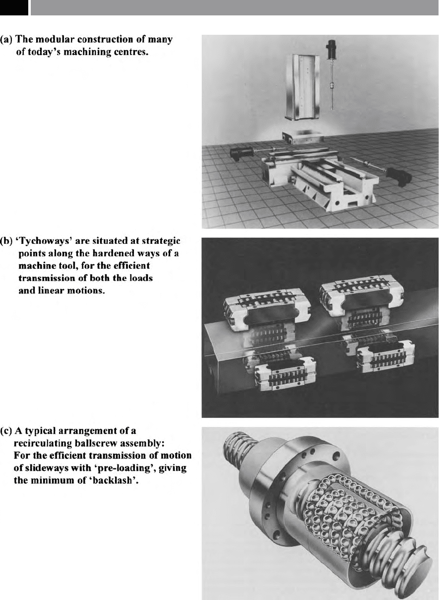
Figure 217. Typical ‘modular design’ and construction of machining centres, with ‘ballscrews’ and ‘tychoways’. [Courtesy of Cin-
cinnati Machines]
.
438 Chapter 9

7 µm. However, if linear encoders are tted this mini-
mises any potential ‘ballscrew wind-up’ , although the
problem of an ‘
Abbé -error’
7
is still present.
Yet another source of machine tool-induced prob-
lems are more specically termed ‘
uncertainties’
8
,
while ‘
hysteresis’
9
can also contribute to the overall ‘er-
ror budget’. us, hysteresis may result when the same
position has been commanded by the CNC controller,
7 ‘Abbés Principle’ – was derived by Professor Ernest Abbé in
1890 (i.e. having studied and graduating from the University
of Jena) and is still valid today. e Abbé principle simply
states that: ‘e line of measurement and the measuring plane
should be coincident’. An example of this ‘Abbé Law’ well-
known to engineers the world over, shows that a conventional
micrometer calliper ‘virtually-obeys’ the ‘Abbé principle (i.e.
there is a small ‘cosine error’ present – which can usually be
ignored), whereas, the Vernier calliper has a much larger o-
set between the xed and moving jaws – where the compo-
nent being measured is situated, to that of the beam – where
the scale’s reading for this measurement is taken. Ideally, both
measurement and reading should be lined-up, without an o-
set. [Sources: Busch, 1989; Whitehouse et al., 2002]
8 ‘Uncertainty of machine tool positioning’ – the question oen
asked in calibration-related tasks, is: ‘What is measurement
uncertainty?’ Uncertainty of measurement refers to the doubt
that exists about any measurement; there occurs a margin of
doubt for every measurement. is expression of measure-
ment uncertainty raises other questions: ‘How large is the mar-
gin?’ and ‘ How bad the doubt?’ Hence, in order to quantify
uncertainty two numbers are required: (i) being the width of
the margin – its interval, (ii) plusits condence level.
NB
is latter value states how sure one is that the actual
value occurs within this margin.For example:On a CNC ma-
chine tool, the command may be to move the X-axis slide-
way 1000 mm plus, or minus 0.05 mm at the 95% condence
level. is uncertainty could be expressed, as follows: X-axis
slideway motion = 1000 mm ± 0.05 mm, at a level of con-
dence of 95%. In reality, what this statement is implying to
either the programmer, or calibration engineer is that they are
95% sure that the actual X-axis position now will lie between:
999.95 mm and 1000.05 mm. Many factors can contribute to
the overall ‘error budget’ as it is sometimes known, but this is
beyond the scope of the present discussion – see references for
further information. (Smith, 2002)
9 ‘Hysteresis’ ,
can be dened as: ‘e dierence in the indicated
value for any particular input when that input is approached in
an increasing input direction, versus when approached in a de-
creasing input direction.’ (Figliola and Beasley, et al. 2000)For
example:Hysteresis usually arises because of strain energy
stored in the system [i.e. in this case, within the machine
tool], by slack bearings, gears, ballscrews, etc. (Collett and
Hope, 1979)
but from opposite directions, causing the motion sys-
tem to creep by an amount larger than the backlash
alone (i.e. the hysteresis). is eect is the result of un-
seen working clearances and compounded by the ma-
chine’s elastic deformations, although by pre-loading
the ballscrews it will minimise some of these eects.
In HSM machining applications, all ballscrew and
indeed any screw-driven systems have some additional
limitations, such as its ‘critical speed’ of rotation. At the
critical speed, a ballscrew starts to resonate
10
at its rst
natural frequency (i.e termed ‘whipping’). Hence, the
critical speed is proportional to the ballscrew’s diam-
eter and is inversely proportional to the distance be-
tween the screw’s supports – squared. For a very long
and slender screw-driven machine tool application
with wide supports, here, most recirculating ballscrews
w
ould have a critical speed of approximately 2,500 rev
min
–1
. It should also be said, that for many ballscrews
assemblies they can be rotated at higher rotational
s
peeds than the 2,500 rev min
–1
previously mentioned,
before they reach their critical speed, but for very fast
accelerations and decelerations, then they become in-
creasing challenged. In fact, on some HSM machine
tool congurations, multi-start ballscrews have been
employed to increase linear response, but here the
‘critical speed’ will probably be lessened – due to re-
duced inherent ballscrew stiness. Even ‘matched’ twin
ballscrews have been tted to HSM machine tools – to
minimise any potential ‘yawing motions’ at high lin-
ear speed by the moving member along the machine’s
bedway. ese ballscrew limitations are probably why
linear-motional drives are becoming a realistic alter-
native, but they are only tted at present, to high capi-
tal cost HSM machine tools.
One of the bi-products of HSM’s greater stock re-
moval rates, is the excess volume of hot swarf which
must be speedily and eciently removed from the vi-
cinity of the machine – which is more readily achieved
for horizontal machine tool congurations. er-
mal eects in general on any machine tool become a
problem, particularly as many milling spindles utilise
direct-drives, with the motor being mounted in-situ
with the spindle. Here, the spindle motor creates heat,
the thermal eects of which can be analysed by either
10 ‘Resonant frequency’ , can be dened as: ‘e frequency at
which the magnitude ratio reaches a maximum value greater
than unity.’ (Figliola and Beasley et al., 2000)
Machining and Monitoring Strategies 439

a three-, or ve-probe spindle analyser, as depicted in
Fig. 218 along with a typical case-study for a spindle’s
thermal dri graph. Not only can such spindle analysis
equipment determine a spindle’s thermal growth, it can
also detect: thermal distortion; spindle error; machine
resonance; vibration; plus repeatability. In the case-
study graphically-depicted in Fig. 218b, the variation
in the machine tool’s temperature is the major cause
of positioning error. is thermal dri graph oers-up
a number of signicant questions that need to be ad-
dressed, such as: ‘How long does it take for the machine
tool to stabilise?’; ‘How much Z-axis growth does the
machine produce at full spindle speed?’; ‘How far has
the machine’s displacement become, because of distor-
tion in the machine tool structure?’. Spindle analysers
are able to operate at rotational speeds varying from
0
to 120,000 rev min
–1
, making them an ideal tool for
condition monitoring diagnostics on machine tool’s
equipped with HSM spindles for subsequent analyses.
In Appendix 15, a trouble-shooting guide has been
produced to high-light: problems; causes; tests; etc.;
that can be obtained from analyses by employing ma-
chine tool spindle analysers.
In Fig. 219, the polar plots illustrated show how the
spindle analyser has the ability to evaluate both a new
and rebuilt machine tool spindle’s condition. In the
spindle error indicated on the polar plot depicted in
Fig. 219a, it illustrates here, that a very badly rebuilt
spindle is simply not acceptable in this state. is poor
spindle performance, is in the main, largely the result
o
f signicant radial variability (i.e. total error: 12 µm
@ 4,005 rev min
–1
), which would severely compro-
mise any cutting tool’s machining performance. Con-
versely, in Fig. 219b, a well-worn spindle assembly is
s
hown prior to rebuild, having a total error of 4.6 µm
@ 1,702 rev min
–1
, aer its ‘correct’ rebuilding (Fig.
219c), the total error has been drastically reduced to
a
total error of 1.9 µm @ 1,700 rev min
–1
. Visually, the
dierences between these two polar plots is quite as-
tounding, in that both the asynchronous and average
errors present have virtually disappeared in the latter
case, making it ‘as-new’ and, ready to perform signi-
cant machining service. It is well-known fact by ma-
chinists familiar with their older and heavily-utilised
machine tools, that certain machine spindles will run
smoother and produce better machined roundness on
w
orkpieces if they are run at the so-called ‘sweet-spot’ ,
equally, the quality of the parts produced will be af-
fected if the spindle is run at its ‘sour-spot’. By utilis-
ing a spindle analyser, signicant information can be
gleaned from such rotational analyses, allowing speed
ranges to be selected which would currently optimise
the present status of the spindle’s condition, prior to
its potential rebuild – when called for at a due date in
the future.
For most machine tools today that are involved in
HSM activities, in general the spindle cartridges are
of three distinct design congurations – which inci-
dentally do not normally include ball bearing spindle
types
11
, such as:
•
Magnetic ‘active’ spindles (Fig. 220a) – typically
might have a cartridge with a speed range from:
4
,000 to 40,000 rev min
–1
, delivering 40 kW con-
tinuous power, peaking at over 50 kW . Such ‘active’
magnetic spindles can maintain 1 µm maximum
run-out, by digital control of the series of speci-
cally-orientated magnetic currents – being initi-
ated by radial and axial sensors, that continuously
monitor the spindle’s rotational axis position 10,000
times second
–1
,
NB F
urther renements to the spindle occur, with
these temperature-controlled milling spindle car-
tridges maintaining dynamic balance, regardless of
the milling cutting loads imposed, this latter fac-
tor being an important criterion when attempting
to reduce cutting tool vibrational eects. However,
these ‘active’ spindles are not cheap to purchase and
run, with another negative eect being that they are
normally rated for only several thousand hours op-
erational running time. Such cartridges come with
a variety of rotational speed ranges and spindle
power outputs.
•
Pneumatic spindles – have been available for many
years, with aerostatic bearings equalising the forces
exerted while cutting and remaining centralised
within the spindle’s housing, yet still achieving dy-
namic rotational balance,
11 ‘Ball bearing spindle designs’ , are not normally specied for
HSM operations, because at around 20,000 rev min
–1
– this be-
ing ‘mechanically-set’ as the upper rotational velocity of such
spindles. So, due to these high rotational speed eects and of
the combination of centrifugal forces, it means that at approx-
imately 80 m sec-1 rotational speed, the balls will lose contact
with the journal walls. As a result of this loss-of-contact the
hardened balls and raceways will rapidly wear out (i.e. the re-
sults of so-called: ‘Brinelling’ in the raceways, creating both
poor circumferential wear patterns, delaminations and associ-
ated frictional eects – leading to major debilitating spindle
roundness modications.) (Smith et al., 1992)
440 Chapter 9
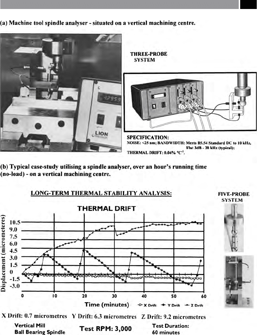
Figure 218. Machine tool spindle analysis system. [Courtesy of Lion Precision].
Machining and Monitoring Strategies 441
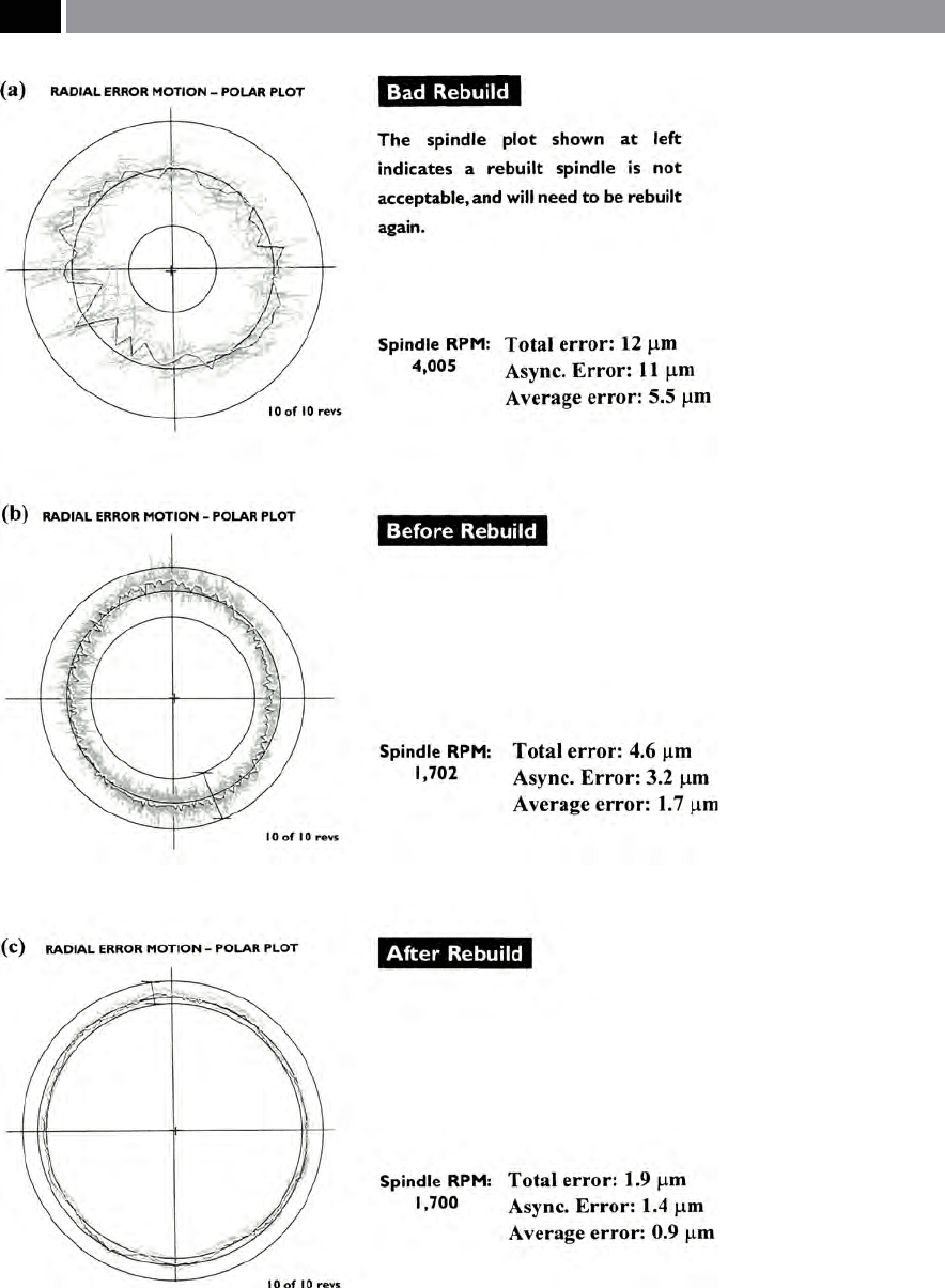
Figure 219. Machine tool spindle error plots, illustrating spindle condition. [Courtesy of Lion
Precision]
.
442 Chapter 9