Smith G.T. Cutting Tool Technology: Industrial Handbook
Подождите немного. Документ загружается.


e capacity for the workpiece, or even a chuck
component to cause damage, or personal injury is di-
r
ectly related to its kinetic energy (KE). us, the kin-
etic energy of a body is proportional to the square of
its speed. As a consequence, the capacity of a fast ro-
t
ating body (i.e. chuck assembly) such as a 1 kg work-
p
iece rotating at 2,000 rev min
–1
would have a KE of
≈ 7 Joules , whereas at 6,000 rev min
–1
the value would
be 62 Joules – approximately the same as a small cali-
bre (0.25) handgun bullet ballistically hitting a target
a
t 100 m range! Even though the KE of the workpiece
represents a serious safety hazard, the energy stored in
the clamping jaws is far greater. For example, a chuck
assembly tted with its jaws (i.e. shown in partial sec-
tion in Fig. 229b) of φ2
00 mm rotating at 6,000 rev
min
–1
would produce a KE of 1460 Joules (Fig. 229c),
which is about the same as a 0.44 Magnum handgun
bullet as it ballistically-issues from the muzzle! With
only 33% of the static clamping force remaining at
the maximum chuck rotational speed, there is con-
siderable energy being stored in the rotating chuck
assembly. It is important that operators understand
how to determine safe operational speeds when using
non-standard jaws, coupled to its residual grip, while
having an appreciation of the energy stored in these
rotating parts.
As one might surmise from the application of HSM
turning chucks, friction plays an important role in
terms of the chuck’s actual performance in-service. Of
note, is that a freshly-assembled and greased power
chuck will oen exceed its maximum clamping force
by almost 20%, despite this fact, aer a few weeks of
use, or indeed non-usage, the maximum-rated clamp-
ing force may be reduced to as little as 30%. is
considerable drop-o in clamping performance is at-
tributable to the absence of eective lubricant and the
presence of particulates on the chuck’s sliding surfaces.
Substantial losses can result even when the chuck has
been frequently lubricated, resulting from the wrong
grease, or deposits that are not periodically removed.
In essence, grease comprises of oils and solids that are
bound together with soap. us, the oils lubricate the
sliding surfaces and the purpose of the solids are two-
fold: rstly, they impede the escape of oils when the
pressure between the sliding surfaces would usually
squeeze them away; secondly, they directly lubricate by
a shearing mechanism at higher pressures. So, greases
having a higher solid content would normally produce
optimum clamping performance. However, when em-
ploying the chuck in the regions HSM, the centrifugal
eects act to separate out the solid and oil constitu-
ents of the grease, causing the oils to be thrown out
of the chuck and leaving solid matter remnants. Over
an extended time period, these solids from the grease
collect in various: gaps; recesses; and cavities; combin-
ing with small amounts of debris (e.g. nes and parti-
cles) generated during previous machining operations,
which impair the chuck’s performance. While the ap-
plication of coolant exacerbates this situation still fur-
ther, as it tends to leach-away the grease and accelerate
its break-down, possibly causing corrosive damage to
a very expensive chuck. In order to combat these un-
desirable eects, additional compounds are necessary,
such as polymers that can improve the lubricant’s: co-
hesion; adhesion; and water-resistance.
Special care must be utilised to ensure that a chuck’s
reliable performance occurs when HSM operations are
employed, as they are especially susceptible to cen-
trifugal separation and leaching of grease – by coolant
application. Under such circumstances, it is probably
advisable to monitor the chuck performance over a
period of time and apply grease, or service the chuck
once a certain wear pattern emerges allowing one to
create a specic maintenance schedule. Measurement
of chucking performance is vital and simply applying
grease at regular intervals is no guarantee of its per-
formance.
When a chuck becomes congested with solid mat-
ter – separated grease constituents, it prevents fresh
grease from reaching the critical surfaces, so in eect
provides little, or no improvement. Clamping force
measurements should be taken both before and aer
the application of grease, so ensuring that it is evident
as to whether, or not, the chuck needs to be serviced/
cleaned. Measurements of the static and dynamic
clamping forces can be simply determined using a ‘Ra-
dio Frequency Gripmeter’ (RFG). e RFG essentially
comprises of just a load cell and handset. e load cell
is clamped in the chuck’s jaws and the handset displays
the measured clamping forces (i.e. the ‘grip‘ being
accurate to 1kN per jaw), thus avoiding any lengthy
and time-consuming calculations. ese RFG’s are
available from reputable chuck manufacturers, with a
typical handset being able to store up to 120 separate
readings, having a PC-link to Windows
©
compatible
soware, allowing graphical trends and further ana-
lyses to be undertaken – as necessary.
In any HSM applications for turning, ‘centrifugally-
balanced chucks’ can be utilised as they incorporate
a counter-balance mass that equalises the centrifu-
Machining and Monitoring Strategies 463
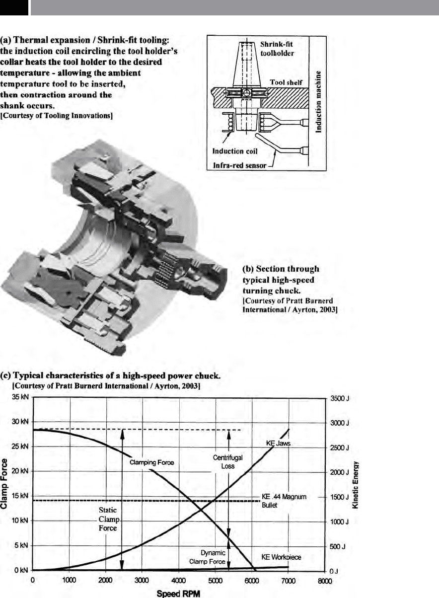
Figure 229. Thermal expansion tooling its operation and high-speed turning chuck details.
464 Chapter 9

gal loss of the jaws – when rotating at typically high
turning speeds (i.e see Fig. 229b for a diagrammatic
cutaway assembly of an HSM quick-change chuck).
ese quick-change chucks incorporate a traditional
w
edge-style and lever mechanism, that instead of dir-
ectly acting on the jaws, the radial force acts through
the actuator and lever mechanism, prior to transfer-
ring the eort to the jaws. So, when the chuck rotates
at high-speed, the actuators are thrown outward by
centrifugal force, but are restrained from moving by
the lever, which pivots about the central connected
sphere. At the opposite end of the lever, the jaws are
also thrown outward and act to move the pivot in the
opposing direction (i.e. to that of the actuators) – ef-
fectively balancing each other. e performance of the
counter-balanced chuck depends upon the accuracy of
the balance achieved, as the actuator mass is constant
and the top jaw mass being variable depending upon
the particular top jaws in use, thus the state of the
balance will also vary. As a consequence, the clamp-
ing force may fall with rotational speed, or actually
increase with heavy and light jaws, respectively. With
standard hardtop jaws, the clamping force remains al-
most constant across the range of the operating speed,
making it unnecessary to calculate the clamping force
losses. An additional feature is that the static clamping
force can be much lower, since there is no centrifugal
loss. is lower static clamping force application, has
the benet that when turning either thin-walled, or
more delicate workpieces that may otherwise distort
with higher clamping forces, such chucks are unlikely
to aect these components, when an HSM turning
strategy is utilised.
Much more could be said concerning HSM turn-
ing operations, particularly relating to the calculations
and working practices, but it was not the intention
h
ere, to give a comprehensive account of such tech-
nical aspects, simply a concise account of the antici-
pated problems and possible solutions when turning
at high rotational speeds. In the following section, a
discussion concerning toolholder coupling to the ma-
chine tool’s spindle will be briey reviewed.
9.4.2 Toolholder Design
and Spindle Taper
Introduction
In the past, the taper cone and its associated driving
dogs and pull-stud, provided adequate location and
torque for the cutter assembly when mounted into
the machine tool’s spindle. e tool’s cone taper an-
gle was adequately manufactured so that it perfectly
‘wedged’ into its mating spindle taper and the prob-
lem of the single-contact mechanical interface was not
really exposed as decient, until very high rotational
speeds were being utilised, coupled to much greater
feedrates that the newly-developed tooling geometries
and tool materials could now exploit. In recent years,
both dual- and triple-contact tooling systems have
been introduced, these designs will now be briey re-
viewed.
Dual-Contact Tool/Spindle Design
One of the most signicant developments in maintain-
ing a complete mechanical interface between the tool-
holder and the machine’s spindle was the dual-contact
7/24 taper system
24
. e CAT Standard incorporates
this 7/24 taper, but also allows simultaneous contact
on both the toolholder’s ange and taper, when HSM
machining is the requirement. By achieving this dual-
contact, the CAT-shank toolholders minimise any
f
orm inherent imbalance at say, 2,000 rev min
–1
. How-
ever, if the cutter assembly is to be rotated at 10,000 rev
min
–1
, the toolholder must cope with a × 25 increase
in centrifugal force, which may compound any unbal-
ance present in the tooling assembly. Further, if the ro-
tational speed is increased still further, into the HSM
r
ange, then here, the centrifugal force is × 100 greater
and the onset of considerable imbalance may create
chattering conditions. At such high rotational speeds,
if coolant is utilised in the machining process, the
HSM conditions could develop a vortex around the
cutting tool, that conventional ood coolant pressures
cannot penetrate. In these circumstances, possibly the
only realistic option is to utilise a through-the-spindle
coolant delivery application at pressures of >690 kPa
(i.e. 1,000 psi), coupled to perhaps, micro-ltration of
the coolant with special pipes and couplings. e CAT
system of dual-contact oers reasonable rotational
control of the tooling assembly at moderate-to-high
rotational speeds, as the mechanical interface system
of face-and-cone provides a certain security against
24 ‘Dual-contact 7/24 taper system’ , refers to the taper being to
the 7 inches of taper per 24 inches of length. is 7/24 system
incorporates several Standards: CAT and BT 40- and 50-taper
tooling.
Machining and Monitoring Strategies 465

the onset of imbalance. Typical applications for these
HSM dual-contact systems include: aerospace part
production; precision die and mould making; automo-
tive component production; as well as medical compo-
nent manufacturing.
It is worth digressing somewhat, to explain the situ-
ation of why the single-cone mechanical interface is
simply not eective for HSM production applications.
W
hen rotational speeds begin to approach 20,000 rev
min
–1
, it is not an unusual occurrence for the single-
contact conventional, or standard CAT V-ange tool-
ing assembly to be eectively sucked into the spindle
(i.e. as there is no mechanical contact at the ange),
this being the result of a combination of the pull-stud
pressure and the machine’s spindle ‘taper swelling’ – due
to the very high centrifugal force acting at such high
rotational speeds. In fact, this minute amount of ‘taper
swelling’ can cause the tool holder to separate from
the spindle’s surface and as a result cause considerable
damage to both the cone’s male and female surfaces.
In order to alleviate this HSM problem and run the
tooling assemblies at even faster rotational speeds, the
HSK dual-contact toolholders were developed, which
will now be briey mentioned.
Hsk Dual-Contact Tooling
ere are a number of toolholder designs that are al-
ternatives to the conventional steep-taper spindle con-
nection. Probably the most popular version for HSM
is the HSK-designed tooling connection (i.e see perti-
nent HSK tooling details in Fig. 126c). HSK toolholder
connections oer simultaneous tment on both the
taper and face, at the front of the spindle. e reason
for their acknowledged popularity amongst the HSM
machining companies, is because the increased rigid-
ity of the joint, coupled with their inherent reduction
in dimensions, compared to the equivalent conven-
tional steep-taper connection. In Fig. 126c, the HSK
8° (included angle) short taper with its gauge face con-
tact and simultaneous taper interference can be seen,
which was designed in Germany to Standard: DIN
69893, being introduced in 1993. HSK is a German
acronym that translates into English as: ‘Hollow short
taper’. us, the HSK connection provides:
•
both high static and dynamic stiness,
•
oering great axial and radial repeatable accuracy,
•
with low mass and stroke,
•
having inner clamping.
erefore, with all these proven design advantages
over conventional spindle connections, it allows the
HSK tooling assemblies to utilise the increased rota-
tional speeds necessary for an HSM strategy.
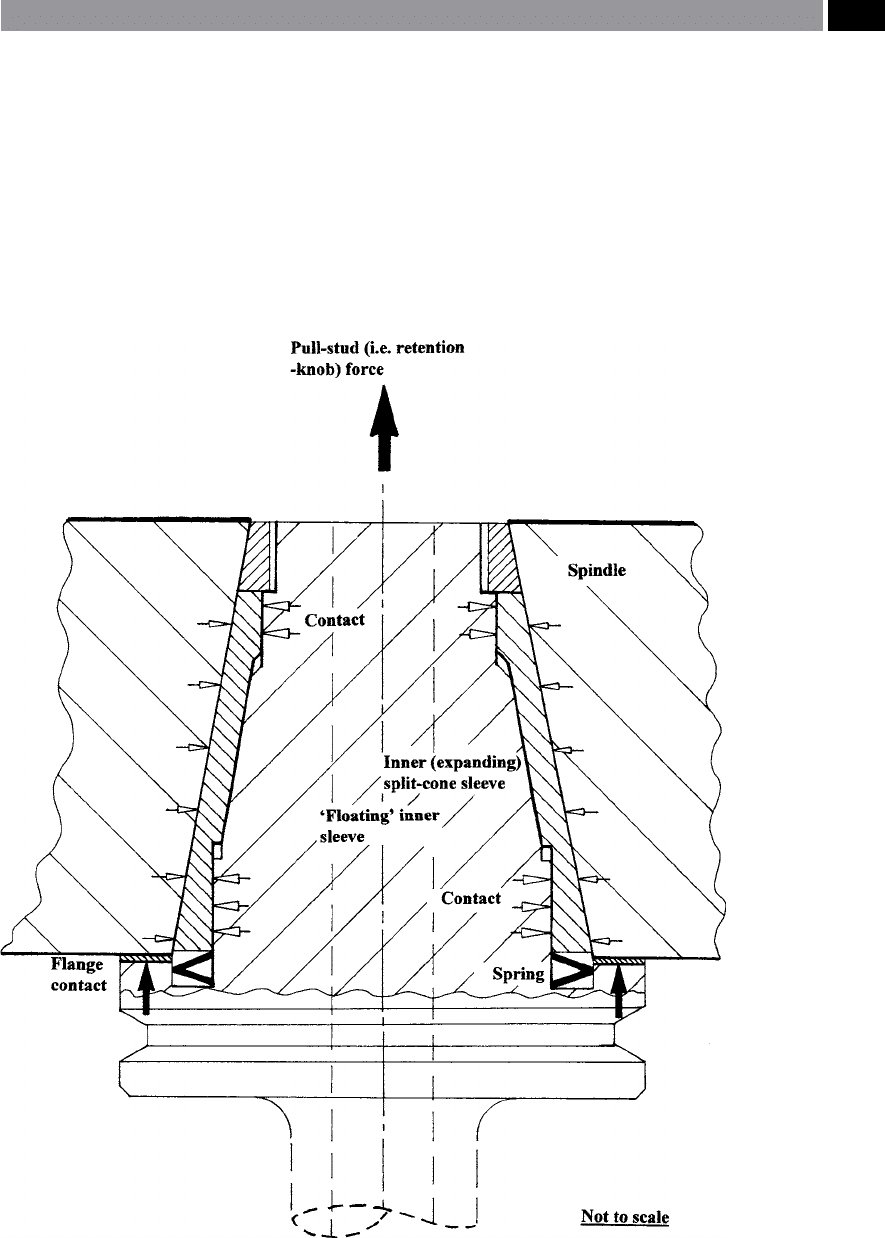
Triple-Contact Tool/Spindle Design
e triple-contact connection is being oered by a
few toolholder manufacturers (i.e. shown in Fig. 230).
e triple-contact design relies on an inner expand-
ing sleeve which maintains uniform contact between
the machine tool spindle and the: toolholder’s top ta-
per; bottom taper; and ange; this being regardless of
the spindle speed employed. Of particular note is the
i
nner expanding sleeve which functions particularly
well at high spindle speeds. So, as the centrifugal forces
increase – with higher rotational speeds, it causes the
spindle to grow (i.e. ‘swell’), the toolholder’s spring
mechanism forces the split-cone sleeve to proportion-
ally-expand with the spindle. Further, the expanding
sleeve also acts as a vibration-dampening device. e
expanding sleeve extends the tool’s life on average by
between 300 to 500%, by virtually eliminating vibra-
tion. As a result of this ‘vibration-free interface’ be-
tween the tool and workpiece, it provides smoother
machining of: tool steels; aluminium alloys; plus other
metallic alloys. is triple-contact connection system,
also performs eciently with extra-long tools (i.e see
Fig. 231), notably when utilised on horizontal machin-
ing centres. e main reason for the enhanced triple-
contact tool’s cutting performance with extended
tooling assemblies, is the result of the ‘oating’ inner
sleeve (Fig. 230) which acts to minimise any potential
Z-axis deection, thus maintaining its rotational con-
centricity.
Such triple-contact tooling is not inexpensive to
purchase, but these toolholders really do amortise
their cost, by signicantly extending cutter life, while
improving part production rates. Further, it is claimed
by the tooling manufacturer that the toolholder is
‘
maintenance-free’ , while its spring-mechanism in
‘life-testing’ has achieved upward of one million tool
changes. With the advent of either the double- and
triple-contact systems, enabling contact between the
machine tool’s spindle and the toolholder’s mechanical
interface: top-taper; bottom-taper; plus ange; while
‘eliminating vibration’; this has been achieved under
the unique conditions that arise with today’s HSM and
high-accuracy and precision manufacturing needs.
466 Chapter 9
9.5 Dynamic Balance of
Toolholding Assemblies
Introduction
Balancing tools that are intended for HSM applica-
tions is vitally important and there are quite a few In-
dustrial/Manufacturing engineers and users who do
not really understand the concept of how to achieve
balanced tooling, or why it is really necessary. Either
very long extended tooling required for say, for deep-
pocketing (Fig. 231), or tooling that is out-of-balance,
will more than likely produce: chattering eects; goug-
ing of a step, or face; loss of workpiece accuracy and
precision; not to mention uneven and premature cut-
ter wear. Whenever a new tooling assembly is destined
Figure 230. Triple-contact tool connection
system is ideal for any potential HSM operations.
[Courtesy of Heartech Precision Inc. (HPI)]
.
Machining and Monitoring Strategies 467
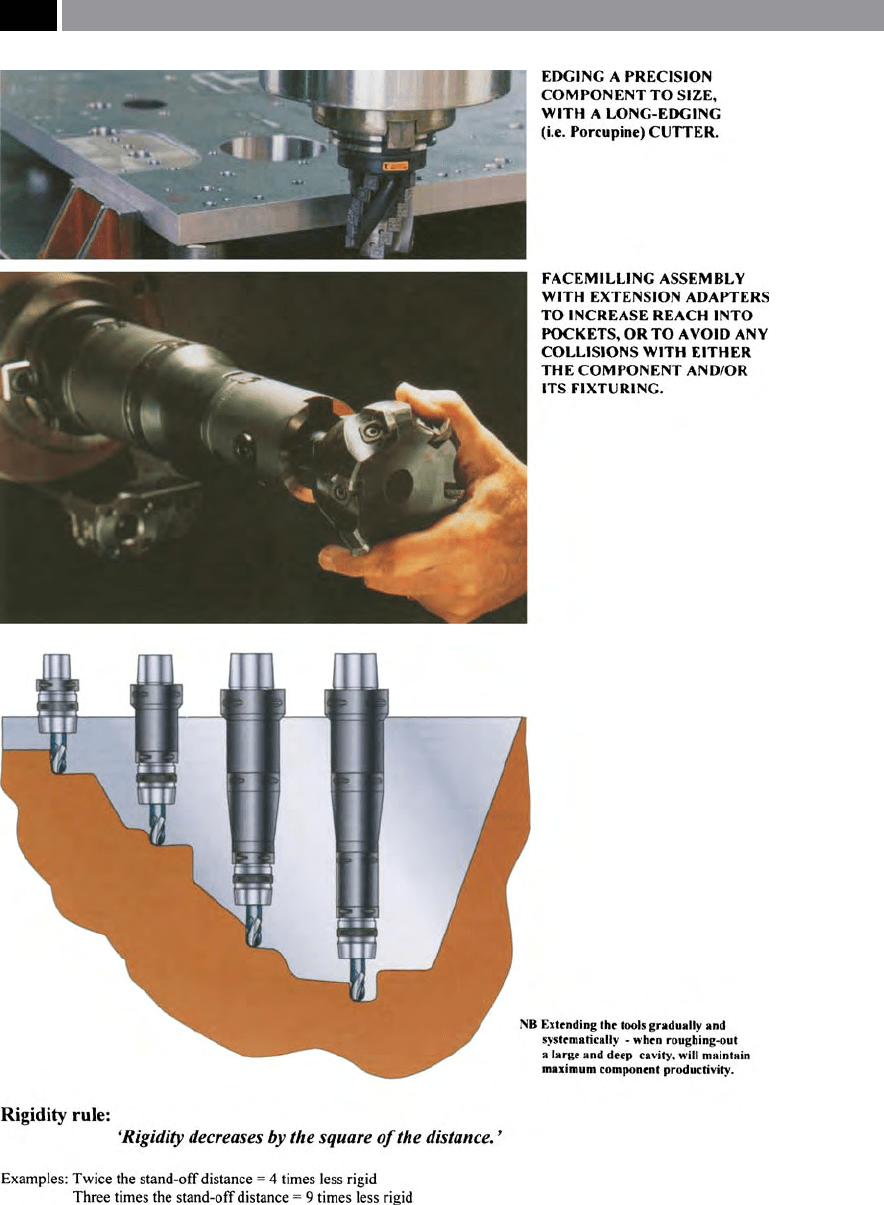
Figure 231. Tool runout (≥10 µm) should be of prime importance when machining deep pockets. [Courtesy of
Sandvik Coromant]
.
468 Chapter 9

for HSM applications on a workpiece, a balancing
operation needs to be undertaken, this statement is
also true for many sub-HSM applications, particularly
when extended tooling is used for whatever reason
(Fig. 231). In fact, every rotating object (i.e. chuck, or
tooling assembly, etc.), will generate vibration.
As has been explained in the previous section, this
vibration results from a number of sources, but princi-
pally here, from centrifugal forces produced by the ro-
tation of an unbalanced mass. ere are several types
of unbalance that could arise, but here, we are mainly
concerned with what is termed dynamic unbalance,
w
hich increases by the square of the rotational vel-
ocity. For example, any vibration produced by a tool-
i
ng assembly at 3,000 rev min
–1
, is × 100 greater than
an identical tooling conguration that is rotating at
3
00 rev min
–1
. Moreover, what is oen either misun-
derstood, or indeed overlooked, is that any change to
the tooling assembly – no matter how small it might
seem, requires re-balancing! ese tooling modica-
tions include any occasion when a cutting tool is ad-
justed, or changed, or similarly if the toolholder is also
either adjusted, or changed. Such changes to the ‘sta-
tus quo’ of the tooling, will directly aect its ensuing
balance, even minutely when just a ‘few microns’! So
that, these miniscule changes to the tooling’s dynamic
condition, causes a degree of tooling oscillation, hence
an out-of-balance condition – with the likely problems
that this creates.
With the wide variety of tooling that is held in: tool
storage carousels; magazines; turrets; etc.; they must
all be ‘balanceable’ by some means. A range of balanc-
ing techniques can be employed here for either single-,
or dual-plane balancing – more will be said concerning
these eects will be made in the following section. e
techniques utilised in achieving tool balance could in-
clude:
•
‘Hard-balancing’ (i.e. see Fig. 234b) – when the
complete assembly either has to have material re-
moved, or added at a certain part of its assembly.
NB
e major problem associated with ‘hard-bal-
ancing’ is that if the tooling setup changes, so will
the likely rotating mass change, which will mean
modifying the amount of material to be either
added, or subtracted from this newly-distributed
mass,
•
‘Adjustable balancing rings’ (i.e. see Fig. 232) – by
rotating the twin lower and higher balance rings
either clockwise, or anti-clockwise they minutely
modify the balance-condition, allowing single-
plane balance to be achieved.
NB
ese matched pair of balance rings are in a
symmetrical state of unbalance (i.e. they are both
‘unbalanced’ to the same degree). Letting the user
adjust the pair to counter any unbalance in the cut-
ting tool/toolholder assembly and locking them
into place – usually achieved on commercially-
available balancing machines (i.e. see Fig. 234a).
e state of unbalance is not merely a subject to the
‘caprice’ of the machine tool operator, a tool assembly’s
balance is given by various quality Standards, such
as ISO 1940/1, or ANSI S2.19 – being basically exact
reections of each other. In the following related sec-
tions, they deal with how and in what manner rotat-
ing cutter assembly balance is achieved, utilising such
HSM balance calculations and associated graphical
details as necessary, from these Standards.
9.5.1 HSM – Problem of Tool Balance
Unbalance of a rotating body (i.e. here we are con-
cerned with a complete tooling assembly), can be
dened as: ‘e condition existing when the principal
mass – axis of inertia – does not coincide with its ro-
tational axis’ (i.e. shown schematically in Fig. 232).
For example, such an undesirable state of aairs can
be comprehended by considering the following situ-
ation: if a φ5
0 mm face mill assembly is rotated at
15,000 rev min
–1
, it will produce a peripheral speed
>240 km hr
–1
, which may prove to be disastrous if it is
unbalanced!
Basically there exists, three types of unbalance con-
ditions for rotating assemblies – such as tooling, these
are:
1. ‘Static unbalance’ – single-plane. is type of un-
balance occurs when the mass does not coincide
with the rotational axis, but is parallel to it and the
force created by such unbalancing, is equal to the
magnitude at both ends of the rotating body. us,
if some relief – metal removal (i.e see Fig. 234b) –
on the toolholder body equal to the out-of-balance
mass that occurs, then a nominal static unbalance is
achieved,
2. ‘Couple unbalance’ – Under these circumstances,
the cutter assembly – mass axis – does not coincide
Machining and Monitoring Strategies 469
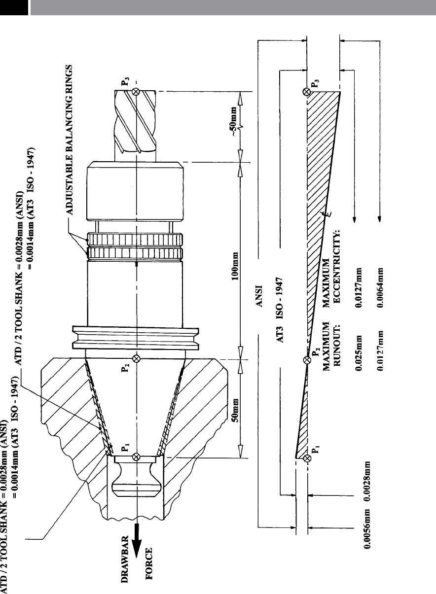
Figure 232. The taper tment against runout/eccentricity for a milling cutter and its associated balanced tool-
holder
.
470 Chapter 9

with the rotational axis, but intersects it at the cen-
tre of gravity of the ‘assembly’s body’. Under such
conditions the force vectors equalise, but are 180°
apart.
3. ‘Dynamic unbalance’ – dual-plane. Such a condi-
tion of the toolholder assembly arises when the axis
does not coincide with the rotational axis and is not
either parallel to, nor intersecting this axis (i.e. see
Fig. 232).
For any rotating tooling assembly, estimating the cut-
ter unbalance is possible using the following variables:
M = cutter/holder mass,
S = mass centre,
e = displacement of mass centre,
r = distance from centre of tooling, to the centre of
gravity of mass (m),
ω = angular velocity,
m = mass unbalance,
U = cutter unbalance,
9549 = a constant.
Determining the relative unbalance (U) of a rotat-
ing tooling assembly, can be found by the following
expression(s):
U = M × e or, alternatively: U = m × r (i).
It is usual to express unbalance in terms of the product
of the mass times distance, typically using the units:
‘g-mm’.
Finding the magnitude of centrifugal force produced
by the rotating tooling assembly with a given unbal-
ance, can be established as follows:
F = U × ω
2
(ii).
Where: ‘ω’ is the angular velocity in units of radians
sec
–1
.
e formula to nd ‘ω’ is expressed by:
ω =
� π � rpm
(iii).
erefore, by combining formulae: (i) and (iii), in (ii),
we can obtain the magnitude of centrifugal force ‘F’ , as
follows:
F = m × r × ( 2 × π × rpm/60)
2
(iv).
As established in equation (iv), the centrifugal force
caused by tooling unbalance will increase by the
‘square of the speed’ , in a similar manner to the spin-
dle nose taper swelling (i.e. growth) previously men-
tioned. Nonetheless, assuming that this specic tool-
holder initially has a low unbalance, this will become a
problem if the rotational speeds are increased beyond
10,000 rev min
–1
. For example, with most toolholders
exhibiting single-plane unbalance
25
, research experi-
mentation has shown that the initial unbalance of a
typical tooling assembly will be of the order: 250 g-
mm. When such tooling is rotated at 15,000 rev min
–1
,
this 250 g-mm of out-of-balance develops a continu-
ous radial force of 642.6 N.
Unbalanced tooling can introduce considerable
detrimental eects on not only the machine tool – this
high centrifugal force causing internal bearing stresses
leading to premature spindle failure, but aects cut-
ter life and degrades workpiece surface texture. Much
of the principal tooling unbalance problems can be
traced-back to several sources, such as:
•
Toolholders of the V-ange type, which might have
dierent depth of drive/slots, these toolholder fea-
tures being part of the inherent design,
•
Toolholders for some end mills and slot-drills, hav-
ing set screws for locking the cutter securely in
place, so due to necessary clearance and the radial
application of the set screw, this creates minute cut-
ter eccentricity – causing unbalance,
•
Out-of-balance caused by an unground V-ange
base,
•
Collet and its collet nut tend to be recurring sources
of unbalance in HSM tool holders.
NB Most of these tool holding-related issues can
be eliminated by simply modifying the tooling de-
sign.
As can be seen from Fig. 232, the marginally eccen-
tric adjustable balance rings can be rotated to adjust
the degree of single-plane balance, with several of the
tooling manufacturers oering diering adjustment
methods for HSM toolholders.
Finally, consideration needs to be given to the level
of balance-quality required and in HSM applications
for example, a milling cutter is expected to withstand
25 ‘Single-plane unbalance’ , relates to the type of unbalance that
occurs in either one of two planes. Namely, the tooling assem-
bly’s single-plane unbalance will be in either its axial, or radial
directional plane.
Machining and Monitoring Strategies 471

both high rotational speeds and associated cutting
forces, thus here it can be considered as a ‘rigid ro-
tating body’. is assumption allows one to use the
ANSI S2.19-1989 Standard, for achieving balance
– see Fig. 233, which denes the permissible residual
unbalance of a rotating body relative to its maximum
speed. is Standard and its equivalents (e.g. ISO:
1940:1; ISO: 1290 G), assigns dierent balance-quality
grades termed: ‘G-numbers’ , related to the grouping of
rotating bodies (i.e. not shown), these groupings be-
ing based upon the experienced gained with a variety
of: sizes; speeds; and types. us, the balance-quality
grade ‘G’ , equals the specic unbalance ‘e’ times the
rotational speed ‘ω’ , as follows:
Balance-quality G = e × ω (mm sec
–1
).
Furthermore, the equation was described earlier, thus:
e =
U
M
(i)
∴ solving for ‘U’ , we obtain:
U =
� M � G
rpm
(v).
From the Standard, the balance-quality for machine
tool drives is given as: G2.5, although in many in-
stances the value utilised should ideally approach that
of G1.0 – this being the specication for grinding ma-
chine tool drives, as today in HSM applications they
are compatible. However, if for the purposes of clari-
cation of the unbalance tooling condition the value
of G2.5 is utilised, then the following worked example
illustrates the balance-quality necessary using a tool-
holder weighing 3 kg, rotating at 25,000 rev min
–1
:
U (higher) =
� � .
,
(g-mm)
∴ U (higher) = 2.85 g-mm.
As alluded to previously, this unbalance condition
is the ‘worst case’ and the tooling should ideally ap-
proach G1.0, this balance-quality value, gives:
U (lower) =
� � .
,
(g-mm)
∴ U (lower) = 1.14 g-mm.
is then follows that the balance is between 1.14 and
2.85 g-mm, which is toward the ‘upper-end’ for the
maximum residual specic unbalance for the G2.5,
while approaching this level for the G1.0 (i.e shown by
the graph in Fig. 233).
Even when the tooling assembly has been dynami-
cally balanced in both planes (i.e. see Fig. 234a – more
to be said on this topic shortly in Section 9.5.2), prob-
lems still exist, particularly in the t of the spindle ta-
per connection (Fig. 232). is is a result of the taper
rate accuracy requirements between both the shank
and taper socket. In fact, the situation is quite a con-
fusing one, due to the relative cone ‘Angle Tolerance’
grades: AT-1 to AT-6, that are employed using the con-
ventional tment of: 7:24 taper. Not only do dierent
countries oen have their own connection Standards,
but previously, even individual machine tool manu-
facturers within each country had adopted diering
Standards! Today, many machine tool companies tend
to utilise taper spindle connections that are compat-
ible to an appropriate Standard and complement those
of the tooling manufacturers.
9.5.2 HSM – Dynamic Balancing
Machine Application
It has been discussed in the previous sections that cut-
ting tool assemblies when combined with an HSM
strategy, can be a large contributor to dynamic unbal-
ance. For instance, in the production and manufacture
of say, the geometry of a face-mill, the tooling stock
material is: externally/internally turned on one side;
unclamped; ipped-over and rechecked; then turned
on the other side; then located onto a milling machine
tool for operations on the individual insert pockets
that must be milled; and indexed
26
– as appropriate
for the number of cutting edges; this necessary clamp-
ing/reclamping workpiece (i.e. face-mill) procedure,
will create a tool that is marginally-unbalanced. With
HSM, the otherwise unnoticeable unbalance at con-
ventional rotational speeds, becomes intolerable in
these high-speed ranges. Oen, the most economical
technique for achieving balanced tooling for tooling
26 ‘Insert pockets’ , are sometimes ‘dierentially-pitched’ which
means they have unequal spacing of teeth around the cutter’s
periphery. is pitching technique for cutting insert pockets,
is quite eective as a means of reducing machining vibrational
eects oen encountered with coarse-pitched face-mills.
472 Chapter 9