Smith G.T. Cutting Tool Technology: Industrial Handbook
Подождите немного. Документ загружается.

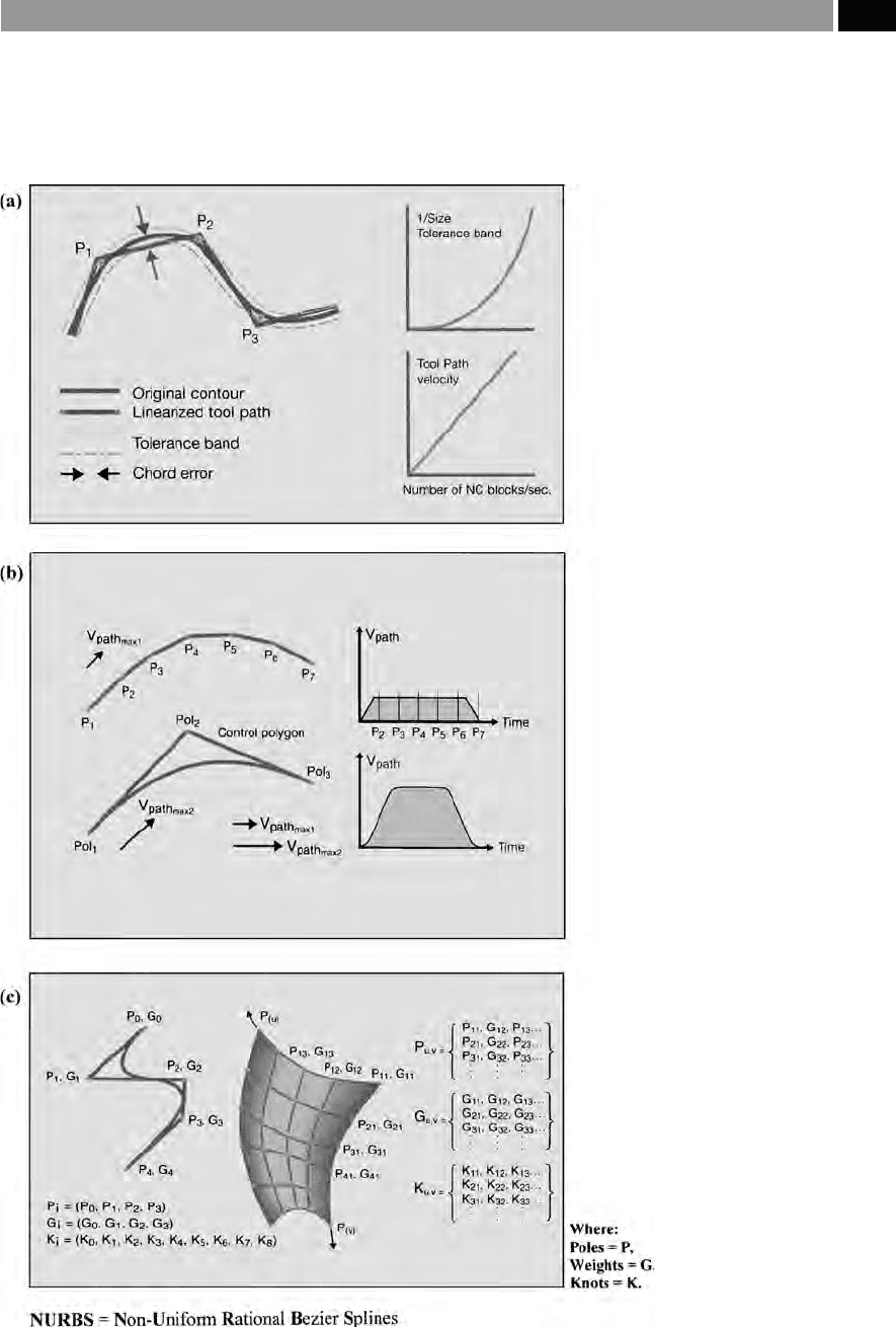
Figure 248. CNT tool cutter path control
while contouring sculptured surfaces – utilis-
ing nurbs. [Courtesy of Sandvik Coromant]
.
Until about a decade ago, there existed only one
practical way to represent free-owing curves in a
cutter path. is was despite the fact that CAD/CAM
systems could mathematically dene virtually any
geometric shape with smooth curves. ese CAD/
CAM systems generated pristine forms which would
Machining and Monitoring Strategies 503

have to be converted into a recognisable program-
ming structure that the machine tool’s servo-drives
could understand and apply. is ‘translation’ took
the form of representing complex curves as a series of
straight lines, or linear segments, being joined end-to-
end within a user-dened tolerance band (Fig. 248a).
us, the length of each linear segment was governed
by the curvature of the prole and the tolerance band
previously set. Any tight precision radii on the work-
piece, requires very small tolerance bands, creating a
large number of segments needing considerable pro-
grammed-blocks of toolpath data. is technique is
acceptable in many respects, but its hardly very e-
cient because complex 3-D surfaces need large quan-
tities of data to accurately represent their geometric
proles. is conict between ‘CAD shape-dening
data’ to that of the machine tool’s motional kinemat-
ics necessary to produce the prole, means that trans-
mission rates and corresponding feedrates suer, as
each line segment corresponds to a ‘bottleneck’ in the
part program, this being data point expressed as an
X-Y-Z co-ordinate. To minimise these problems and
more specically, now that HSM capabilities are com-
monplace, CNC builders are incorporating ‘complex
curve interpolation’ capabilities into their controllers,
enabling tool paths to be machined utilising the same
mathematical terms that CAD/CAM systems use to
generate them. In other words, ‘NURBS’ , which in
practice largely means that for the same quantity of
data, the controller can achieve faster, smoother and
more accurate machining.
A ‘NURBS’ is constructed from three discrete pa-
rameters: Poles; Weights; and Knots
47
. As a result of
‘NURBS’ being dened by non-linear motions, the
tool paths will have continuous transitions, enabling
signicantly higher: acceleration; deceleration; plus
enhanced interpolation speeds; than was previously
47 ‘NURBS’: e rational equation, can be expressed, as follows:
P (t) =
i=
�
n
Ni, (t) GiPi
i=
�
n
Ni, (t) Gi
e Non-Uniform B-Splines can be expressed, as follows:
Ni, (t) =
�
�
�
�
�
�
�
�
�
(Ki � t � Ki + )
< Ki, Ki+ < t)
Ni, k (t) =
(t
−
Ki) Ni, k − (t)
Ki + k −
−
Xi
+
(Ki + k
−t
) Ni + , k − (t)
Ki + k
−
Ki +
Where:
Pi = Control point; Gi = Weight; Ki = Knot vec-
tor.
(Source: Oakham, 1998)
available by CNC controllers without the ‘complex
curve interpolation’ capabilities. As ‘NURBS’ have the
ability to describe any free-form curve, or surface pre-
cisely and eciently, they became immensely popular
with CAD Soware-developers, because it allowed
Design Engineers more freedom to manipulate 3-D
data, than had been available utilising simple ‘line-
segments’ and ‘primitives’. e logical extension for
the application of ‘NURBS’ was followed-up by CAM
developers, as many systems were integrated into one
by the same company that developed the CAD system.
is CAD/CAM integration, enabled these companies
to supply post-processors that supported all the major
digital controller manufacturers oering a ‘NURBS-
capability’.
In order to more fully comprehend just how
‘NURBS’ works, it is worth a slight digression to briey
discuss the techniques utilised to represent curved
surfaces. By way of illustration, the CAD equivalent
of the Draughtsman’s ‘Flexi-curve’ used to create free-
from curves, is termed a ‘spline’
48
. e alternative ‘B-
Splines’
49
dier from that of ‘Splines’ , instead, they
function somewhat like a ‘gravitational pull’ acting on
them, pulling and distorting the curve, but in the con-
trol point’s direction. While, ‘NURBS’ are essentially a
more controllable version of ‘B-Splines’. e resulting
output from ‘NURBS’ is very ecient, as it describes
the curve’s geometry with a fraction of the data output
necessary for linear interpolation. One disadvantage is
that the calculation of ‘NURBS’ are much more com-
plex, necessitating considerable amounts of comput-
ing power to compute them. e ‘Non-Uniform’ term
in ‘NURBS’ , refers to what is called its ‘knot vector’ ,
which indicates the portion of a curve that is aected
by an individual control point, but where it does not
have to be ‘uniform’. By ‘dissecting’ the ‘NURBS’ term
still further, the portion of it aected by the ‘Ratio-
nal’ part of the formula, means that the weight of the
control points’ pull (weighting) – which can be speci-
ed. is ‘weighting’ allows conic sections to be repre-
sented, without having to slice them up to determine
their geometric aspect.
48 ‘Splines’ , can simply be dened as follows: As a series of
equally spaced control points which the computer connects to
create a smooth owing curve’.
49 ‘B-Splines’ , may be dened in a slightly diering manner to
that of ‘Splines’ , such that: Utilising the end and control points
that do not necessarily intersect the curve, thereby they can dis-
tort the curve’. (Source: Oakham, 1998)
504 Chapter 9

When applying ‘NURBS’ to a complex part’s curva-
ture, it is important to recognise that it denes the entire
curve, not just a series of facets, enabling it to express
any curve geometry, utilising less data than for other
‘curve-tting techniques’. Data transmission times are
signicantly improved as a result, this is because one
does not have to transfer all of the curve data, just the:
control points; the order of the polynomial; the knot
vector; and its weighting; as dened by the CAD sys-
tem. Once this has been achieved, the machine tool’s
CNC controller then decodes this information, in or-
der to control its servos. While a single ‘NURBS’ ex-
pression can describe a simple curve, complex curves
(e.g. Fig. 248c) are described by moving ‘weighting’ on
the control points, running the calculation, then mov-
ing the ‘weighting’ again and re-calculating and so on,
in a recursive manner. us, each point moved has
an inuence on the others, but the more the control
points utilised, the less their inuence becomes – in a
similar manner to the so-called: ‘law of diminishing
returns’. ‘NURBS’ is comparable to linear interpolation
in that the greater the accuracy the more the number
of points needed, although it requires less data in to-
tal – with a gure of 60% data-reduction, with an as-
sociated 40% improvement in time, has been claimed.
Although the solution to virtually every curve-tting
g
eometry can be undertaken by ‘NURBS’ , it cannot
partake in all ‘surface-describing miracles’. If the CAD
system outputs poor data, this will end up with a simi-
l
arly pitiable ‘curve-tting routine’ , so as the old saying
goes, it’s the equivalent of: ‘Garbage in, garbage out!’ In
time, these ‘NURBS’ will have even more renements
added to enhance the already powerful ‘curve-tting
processes’.
9.8.4 Sculptured Surface Machining –
Cutter Simulation
Once the free-owing curves for the sculptured sur-
faces have been generated and the actual workpiece
is about to be machined, many companies embark on
a ‘cutter simulation routine’ prior to undertaking any
surface machining. Many of the sophisticated surface
machining soware packages, can provide several
variations of complex surface machining routines.
Typical of such routines, is that shown for a particular
leading company’s product for the multi-axis sequen-
tial machining, depicted in Fig. 249a. is specic
‘sequential surface machining’ routine (Fig. 249a), is
an interactive, graphic implementation of ‘drive-part-
check’ surface machining, as dened in the: Automati-
cally Programmed Tool (APT) Standard. is routine
is greatly enhanced when utilised in combination with
two other machining soware packages, namely: ‘Se-
quential machining’; and ‘Drive curve mill’. While an
enhanced function incorporated into the machining
package is termed ‘looping’ ,
which enables the user to
generate multiple passes on a surface, by dening the
inner and outer tool paths, allowing the system to then
generate the intermediate stock-clearance tool path
steps.
A typical modular-package might oer: surface con-
touring; parameter line machining; rough-to-depth;
and zig-zag tool paths; having any design modica-
tions, or changes being automatically handled through
what is termed ‘associativity’ ,
thereby signicantly re-
ducing any attendant costly, but otherwise necessary
prove-outs. By utilising cutter simulation, parameters
such as: feedrate; spindle speed; and part clearance; are
instantly accessible and, being ‘modal’ they remain un-
changed, unless the user modies these values. While
at any time during the development of the simulation,
a user can test a setting by generating a tool path with
its accompanying high-resolution graphic display (Fig.
249a). Surface machining will automatically simulate
the cutter’s tool path, being displayed on a graphics
screen and generate textural output into a ‘cutter lo-
cation source le’ (CLSF). Aer simulation, the user
may either choose to accept the tool path simulation
and then save these parameters, or reject it and modify
whatever parameters are necessary to correct for any
attendant problems encountered. It should be stated
that if a problem had occurred when actually cutting
the complex geometric component’s surface – such as
‘
surface gouging’
50
, this would have probably scrapped
the otherwise expensive stock of workpiece material,
that has also added signicant value to it, by the time-
consuming process of machining this part’s intrinsic
geometric characteristics.
So the application of cutter simulation is not only
economic and scally important, it oers many other
signicant production benets. erefore, with such
enhanced cutter simulation, a range of important fea-
tu
res can be addressed ‘o-line’ , such as:
•
Supporting typical CAD ‘Surfaces and Solids’ pack-
ages,
•
Providing both 3- and 5-axis contouring motion –
including tool orientations that may be oset from
50 ‘Surface gouging’ , is if a cutter unintentionally removes mater-
ial (gouges-out) a portion of surface.
Machining and Monitoring Strategies 505
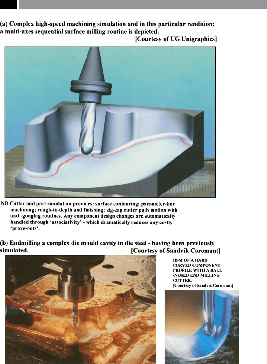
Figure 249. By utilising a sophisticated cutter and part simulation technique, any potential and very costly ma-
chining mistakes can be avoided
.
506 Chapter 9

the surface ‘normals’ (i.e. cutter tilt and lead/lag
angles), or being parallel to the surface (i.e. here,
termed: ‘swarf-cutting’),
•
Gouge-checking routines and step-over control
functions, during the non-cutting motions,
•
Allowing complete control over the quality of the
machined surface texture and the attendant stock
to be removed,
•
Control of intrinsic surface directional parameters,
having input of tool paths that are projected onto a
surface to be machined with its associated arbitrary
c
urves and points ‘sets’ ,
•
Addressing a ‘full-check’ surface capability, having
specied part clearances – for xtures and clamp-
ing, while stipulating both setting and gauging
points in the simulation routine,
•
Allowing for the machining of arrays of multiple
surfaces, including: trimmed and extended sur-
faces; and for any multiple arbitrary holes,
•
Enabling the user to selective in avoiding particu-
lar workpiece features, such as specic holes and
islands.
By utilising sophisticated cutter simulation packages,
the work is undertaken ‘o-line’ by the user, thus
avoiding: costly prove-outs; potential scrappage of
parts; tool breakage; or under extreme circumstances,
even serious damage to the machine tool. In fact, for
any sculptured machining operations (i.e. typied in
Figs.: 245b and c, 246b, 249b), they need to have some
form of cutter path simulation undertaken and its as-
sociated simulated enhancements, otherwise poten-
tially costly production machining mistakes are the
likely outcome.
9.9 Hard-Part Machining
Introduction
Since the development of ultra-hard cutting tool ma-
terials, such as: cubic boron nitride (CBN); and poly-
crystalline diamond (PCD) and their derivatives; to-
gether with ‘sub-micron’ cemented carbides coupled
with their ultra-hard multi-coatings; or diamond-like
coatings (DLC) to these carbide surfaces; it has enabled
the hard-part machining process to become well-es-
tablished and commonplace. Prior to machining parts
in the hardened state, the time-consuming and expen-
sive processes were: rough-out, or nish-machine cer-
tain features of the part, then heat-treat it (i.e. hard-
ening and tempering – as necessary), grinding critical
surfaces and dimensions. Today, by hardening the
wrought stock material before it is machined, this will
eliminate any potential distortions caused by thermal-
inuences on the part when it was heat-treated, this
enables the part to be hard-part machined: roughed
and nished, normally avoiding the subsequent grind-
ing processes: surface and cylindrical – as necessary.
e question that could be asked concerning such a
machining application is: ‘What then denes hard-part
a machining process?’ Before answering this question
it is worth metaphorically ‘stepping-back’ somewhat,
to discuss what was considered as extremely ‘hard’
51
around seventy, or so years ago. At that time, high-
speed steel (HSS) tooling was the norm, as cemented
carbide had not yet been fully-established throughout
the manufacturing industries of the day. Here, HSS
was the favoured tooling material, due to its superior
retained edge hardness at elevated temperatures (i.e
its ‘red hardness’) in combination with its improved
toughness – over other tool materials at that time.
Typically an M2-HSS
52
had a bulk hardness of between
58-64 HR
C
. Returning to the question posed above,
concerning what denes a hard-part, according to one
major cutting tool company it is those materials with
a hardness of >42 to 68 HR
C
53
– being the equivalent
of machining components from M2-HSS. Previously,
only through grinding operations, could the hardened
c
omponent be produced to ‘toleranced-size’ , while
51 ‘Hardness’ , can be dened as: e measure of a material’s re-
sistance to deformation by surface indentation, or abrasion’.
(Source: Callister, Jr, et al., 2003)us, a ‘hard material’ can be
considered, when large forces are necessary to cause a perma-
nent indentation [machining] marks. (Source: Schaer, et al.,
1999)
52 ‘High-speed steel’ (M2 – HSS), will have a typical 0.2% yield
s
tress @ room temperature of ≈3,000 N mm
–1
, while @ 600°C
it is ≈1,800 N mm
–1
, showing good high temperature prop-
erties. Some other relevant mechanical properties, include:
transverse rupture stress @ 4.8 GPa; Fracture toughness (K
IC
)
@ 17 MN m
–3/2
; Izod impact strength (un-notched) @ 33.4 J.
(Source: Trent, 1984)
53 ‘Hard-part machining’ ,
today is utilised widely as both a
roughing and nishing cutting process, which of late, has
seen parts machined from a range of hard workpiece materi-
als, having a bulk hardness of up to 68 HR
C
. (Source: Huddle,
2002)
Machining and Monitoring Strategies 507

having the necessary surface texture. In the case of
hard-part turning – to be discussed in the next sec-
tion, hard-turned surface texture of better than 2.5 Ra,
is achievable, across a range of workpiece materials.
According to Hanson (2005), hard materials can be
classied into two distinct groups:
1. S
ingle-component materials – might typically in-
clude hardened tool steels, glasses such as Pyrex™
and borosilicate, ceramics including silicon carbide
(SiC) and aluminium oxide (Al
2
O
3
),
2. C
omposite materials – could be either metal/ce-
ramics such as metal-matrix composites (MMC’s)
and tungsten-carbide /cobalt, glass/ceramics such
as Zerodur™ and Cervit™, as well as ceramic/ce-
ramic composites such as silicon-carbide/silicon.
NB
ese groupings only list a few of the hard
workpiece materials currently available today, many
more exist, but they can still be classied within
these groupings at present.
e selection of the cutting tool composition and its
associated geometry when hard-part machining, is in-
uenced by the severe demands made by these hard-
ened workpieces. e problems encountered can range
from very rapid tool wear rates, cracks and chipping of
the cutting edge(s), to an unacceptable machined sur-
face condition. Some multi-coated cemented carbides
and aluminium oxide ceramics (Fig. 10) can cope with
some operations on hardened workpiece materials,
but it is more usual to utilise ultra-hard cutting tool
materials, or at the very least, specialised-coatings on
cemented carbide tooling.
Some technical diculties can be encountered
when hard-part machining, these might range from:
•
Elevated temperatures in the cutting zone,
•
Greater and more variable cutting force magni-
tudes,
•
Intense pressure on a relatively small cross-section
of the chip – near the edge,
•
Rapid cutting edge wear, or catastrophic break-
down,
•
Workpiece stresses being released during the ma-
chining operation,
•
Poor homogeneity in part material – creating vibra-
tional eects on tool’s edge,
•
Insucient stability and rigidity – created in the
‘machine-tool-workpiece’ loop stiness.
e extreme thermal and mechanical conditions, will
dictate the manufacturing circumstances, concerning:
tool material and its geometry; machining methods
utilised; together with the cutting data selected. So, the
properties demanded from a cutting tool when one is
about to embark on hard-part machining exercise, are
that it has:
•
Superior abrasive wear resistance,
•
Chemical stability at the high temperatures en-
countered,
•
Ability to retain its cutting edge at high tempera-
tures – ‘hot-hardness’ ,
•
High compression and bending strength,
•
Good cutting edge strength and toughness,
•
Cutting edge inertness and resistance to diusion
wear.
e hardness of a part, should not be confused with
i
ts ‘modulus’ , or the material’s toughness. As it is the
combination of elastic and plastic properties that de-
termine a material’s resistance to yield, namely, its
permanent deformation
54
. In the following sections,
particular approaches to that of hard-part machining
by various production processes will be concisely re-
viewed.
9.9.1 Hard-Part Turning
For some years now the application of hard-part turn-
ing has increased in popularity, as the time needed to
nish these hardened components – with their hard-
nesses ranging between 45 to ≈68 HR
C
– has signi-
cantly reduced. e major time-saving is from the vir-
tual elimination of nish-grinding operations, when
‘ne-turned’ surface texture of <2.5 Ra is now possible,
with matching dimensional tolerances. Complex con-
touring of a component’s prole using hard-part turn-
i
ng operations is achievable (i.e. see Fig. 154 – top),
which overcomes the previously expensive and time-
consuming proling operation of cylindrical grinding
with custom-formed grinding wheels.
However, successful hard-part turning is more than
simply ‘chucking’ a hardened component (Fig. 250a),
54 ‘Yield, or permanent deformation’ , diers here, from that of
either: elastic deformation; or dislocation, slip, etc.; that may
result during machining. (Source: Hanson, 2005)
508 Chapter 9

then utilising for example, either a CBN, or ceramic
cutting insert to machine them. A variety of important
factors require consideration if the turning operation
is to be successful, including the fact that higher cut-
ting forces involved and their aect on the machine
tool’s structural rigidity and stiness (Fig. 250d). ese
hard-part cutting forces can be ≈200% higher than the
forces generated when similar operations are under-
taken on ‘soer parts’.
Due to the fact that either the CBN, or ceramic tool
materials tend to be relatively brittle, cutting tool com-
panies will apply chamfers to the cutting edges – to
strengthen them. A problem with a ‘supporting cham-
fer’ on the insert’s edges is that it reduces its shearing
capability, this causes the cutting forces to increase –
due to the so-called ‘ploughing-eect’. e application
of higher cutting forces here, makes both the insert’s
edge and the part move relative to one another – re-
sulting in chatter. e onset of chatter causes surface
texture degradation – at best, or destroys the cutting
edge/tool and even the part itself – at worst. Moreover,
the size and the shape of the workpiece when hard-
part turning is important, as if too long a length-to-
diameter ratio – without support, this will prove to
be exceedingly dicult to successfully machine. With
some hard-part machining companies stating that L/D
ratios of >3:1 can be a problem – with respect to chat-
ter generation, resulting from the higher imposed cut-
ting forces now in operation.
Workholding plays a crucial role in successful
hard-part turning operations, with a rm all-round
grip – from say a collet positioned and rigidly held
well inside machine’s headstock, is much preferred to
that of a three-jaw chuck – as this latter device may not
necessarily provide either the ‘c
lamping forces’
55
, nor
inherent rigidity. e location of the turning insert’s
55 ‘ree-jaw chucks – clamping forces’ (Fig. 250 – bottom right),
due to the fact that the ‘conventional’ chuck’s self-centring
mechanism is a face-scroll – this being provided by a spiral
groove cut onto the face of a at disk, then having the equi-
spaced jaws oset by the scroll’s pitch and numbered for re-
placement as either internal, or external jaws. When the chuck
key turns the ‘scroll-pins’ which then rotates the scroll plate
and thus, they simultaneously radially move the jaws – in-
ward/outward. So, depending upon the scroll plate’s rotation,
the torque supplied by the chuck key creates only one third of
the total force supplied at each individual chuck jaw. erefore,
the force may not be adequate to provide sucient force to
grip and rigidly hold the part as it is hard-turned.
positional location, relative to the machine’s spindle
bearings is signicant. e further the distance away
from the front spindle bearing’s location relative to
that of the cutting action, the greater any potential for
the part to ex and chatter – acting like a ‘lever mecha-
nism’ (i.e. its force times distance). So, machine tools
that are designed so that their collets are well-seated
into the headstock and close to the front bearings and,
when hard-part turning, the minimum of workpiece
overhangs should be utilised.
Turning centres that are designed from the out-
set to cope with the demands of hard-part turning,
are usually of greater size and weight, plus being ex-
tremely rigid structures. Even here, concerning a ma-
chine’s rigidity, there are practical limits to the amount
of ‘static stiness’ (i.e. the ratio of applied force to that
of an associated displacement) that can be built into
the turning centre. e design objective is to increase
the machine tool’s ‘
dynamic stiness’
56
, which involves
dampening the frequency of vibrations via specic ap-
plied technologies, such as ‘
composite-lling’
57
the ma-
chine bases. While a dierent approach to dampening
vibration, involves the use of hydro-static linear ways,
which ride on non-contact pressurised uid bearing
surfaces. In a similar manner to that of ‘conventional’
linear-ball guide ways, they exhibit low friction and
resist omni-directional loadings (i.e see Fig. 250d – for
a performance comparison of these two linear bear-
ing types). Moreover, hydro-static guide ways provide
dampening as-and-when vibrations occur during
hard-part machining process. Furthermore, hydro-
NB In Fig. 250e on the other hand, the force exerted by this
type of self-centring mechanism, should prove to be able to
cope with the demands of hard-part turning , particularly as
the ‘so-machinable jaws’ have been bored-out, to provide
more circumferential location and support for the part.
56 ‘Dynamic stiness’ ,
can be dened as: e ratio of the applied
force to the displacement, occurring at the frequency of the ex-
citing force’. (Source: Hardinge Inc., USA)
57 ‘Composite-lling’ – machine tool bases. is dampening te-
chinque is traditionally achieved by employing such materials
such as Granitan™ (i.e. typically, being a crushed granite and
epoxy resin), or Harcrete™ – this latter product is a polymer
composite, having an 800% better damping capacity to that of
the equivalent grey cast iron structure. Although these com-
posite-lled structures can be expensive, in order to alleviate
some of this cost, ‘traditional’ castings have strategically-rein-
forced composite-lled cavities. (Source: Kennedy, 2004)
Machining and Monitoring Strategies 509
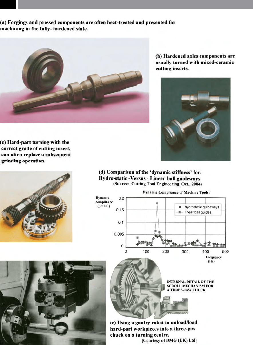
Figure 250. Hard-part turning operations are replacing some grinding operations: assuming dimensional size and
machined surface texture are acceptable. [Courtesy of Sandvik Coromant]
.
510 Chapter 9

static bearings
58
oer the indirect benets of: improved
hard-part machined surface texture; greater compo-
nent accuracy and precision; coupled with increased
tool life. While, due to the fact that hydraulic fuild is
virtually incompressible, if an interrupted cut occurs
for any reason, the tool can later pick-up exactly where
the interruption occurred thereby eliminating the os-
tensibly termed ‘witness marks’ on the machined sur-
face.
Great demands for increased spindle power are
not necessary, as typical D
OC
’s are ≈0.75 mm, coupled
to small feedrates. With for example, the cutting data
for a φ1
2 mm, hard-turned part, might be by utilising
a spindle speed of 4,500 rev min
–1
, which equates to a
surface speed of ≈170 m min
–1
. is is well within the
capabilities of some turning centres today, that have
s
pindle speeds of 10,000 rev min
–1
. As one can gather
from this discussion, hard-part turning and thread-
ing (Fig. 251a) is principally concerned with saving
money, by removing additional and now, superuous
operations from the overall product’s cycle time. It has
been reported by industrial-users, that by utilising a
hard-part turning strategy, then the total time to com-
plete the component has been reduced by up to 75%,
when compared to the traditional approach, of: rough-
turning; then heat-treating; and nally cylindrically
grinding. is latter process of cylindrical grinding,
can still be valid where extremely tight tolerances are to
be held, coupled to when high-quality surface texture
demands are to be met. Oen, both for large-batches,
or if continuous production runs are necessary, for ei-
ther hard-part nished turning, or when cylindrical
grinding, they require critical dimensional tolerances
to be held across certain diameters, or indeed, for their
lengths. In this metrological situation, a ‘receiver gaug-
58 ‘Hydro-static bearing performance’ , is characterised by three
factors, these are its: load-carrying capacity; oil ow-rate; and
pumping power. e magnitudes of the hydro-static coe-
cients depend very much on the pad design, such that:
W = a
f
A
p
p
r
Q = q
f
W/A
p
× h
3
/ µ
P = p
r
Q = H
f
(W/A
p
)
2
× h
3
/ µ
Where: W = Load on the bearing (N); Q = Volume ow-rate of
oil (m
3
s
–1
); P = Pumping power (N × m s
–1
≡ W);a
f
= Pad load
coecient (dimensionless); q
f
= Pad ow coecient (dimen-
sionless); H
f
= Pad power coecient (dimensionless, because
H
f
= q
f
/a
f
); A
p
= Pad area (m
3
);p
r
= Oil pressure in the recess of
the pad (Pa); h = Film thickness (m); µ = Dynamic viscosity of
the oil (Pa.s). (Source: Mott, 1985)
ing’ unit specially-congured to measure such part
dimensional features can be built-up from modular
units and its associated instrumentation (Fig. 252).
Not only can this custom-built receiver gauge assem-
bly (Fig. 252b), simultaneously measure many compo-
nent features quickly, but through the instrumentation
unit (Fig. 252a), ‘Statistical Process Control’ (SPC) can
be employed to up-date the whole process through
‘closed-lop’ feedback to the machine’s controller. is
up-dating will automatically modify the tool osets,
thereby minutely adjusting the process and as such, re-
ducing variability in the process to a minimum. Parts
can be loaded into the adjacent ‘receiver gauge unit’ ,
via
a gantry-robot (Fig. 250e), or alternatively by a ‘dedi-
cated robotic device’. Once held in the robot’s gripper,
the nished hard-turned/-ground part, is manipulated
into the desired orientation by its axes, then steadily
lowers the completed workpiece onto the component
support plates within the receiver unit. In the case of
Fig. 252b, the centres will automatically engage with
the centre-drilled holes, slightly liing the compo-
nent to its measuring height, prior to the measuring
heads progressively moving forward to contact each
machined component’s surface feature – for automatic
measurement and control.
9.9.2 Hard-Part Milling
Introduction
Until relatively recently, the application of HSM by
milling of hardened die and mould steels was consid-
ered something of a ‘black-art’. is is not the case, as
by adhering to some basic machining principles and
guidelines the whole process becomes a somewhat:
straightforward; predictable; and a protable activity.
In eect, there are three primary machining meth-
ods utilised to produce hardened dies and moulds,
although it should be stated that the die/mould con-
guration, along with its respective hardness will de-
termine which technique, or combination of processes
produces the optimum manufacturing route. However,
notwithstanding these circumstances, the primary
methods can be classied as follows:
1. ‘
So machining’ – milling – this is where the part is
‘roughed-out’ prior to its hardening heat treatment.
e technique of ‘so-machining’ is normally con-
s
idered when milling large workpieces, or com-
ponents requiring deep-cuts, or wide features – such
Machining and Monitoring Strategies 511
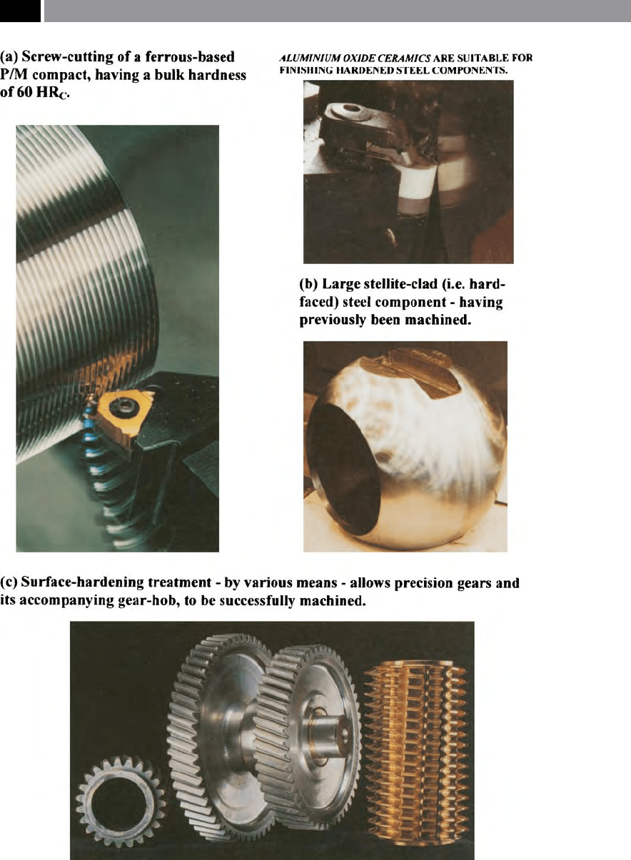
Figure 251. Hard-part machining operations undertaken on many components by through-hardening,
hard-facing or by surface-hardening heat-treatment; are acceptable. [Courtesy of Sandvik Coromant]
.
512 Chapter 9