Smith G.T. Cutting Tool Technology: Industrial Handbook
Подождите немного. Документ загружается.


sizes of 25 µm. is range includes four-ute square-
ended cutters (i.e. similar to the one depicted in Fig.
2
55 – bottom le), together with ball-nose end mills,
plus some customised micro-mill tooling.
Complementary to these micro-milling cutters, are
their respective toolholders
66
, which must hold and
securely contain the tool’s shank in an accurate and
precise manner. Any form of tool runout when held
in the toolholder must be kept to absolute minimum.
e toolholder’s importance in the micro-milling op-
eration is oen overlooked, at the user’s peril! By way
of illustrating this fact, if one has a two-ute φ0
.5 mm
end mill then the chip-load will be <0.010 mm tooth
–1
.
So, if the micro-mill has a runout of 5 µm, the cutter
is only utilising one of its utes – by a factor of 100%.
is micro-mill’s runout condition, leads to cutter in-
stability coupled with a poor milled surface situation,
with the potential for either reduced tool life, or break-
age. Micro-milling tool deection and its subsequent
breakage when utilised for micro-machining opera-
tions, are principally caused by three main factors,
these are:
1. M
icro-machining creates a substantial increase in
the specic energy, as the chip thickness decreases
– meaning that here, as the chip gets thinner with
smaller D
OC
’s, the micro-mill is subject to greater
resistance, when compared to that of ‘macro-mill-
ing’. Moreover, it is almost as if the workpiece mate-
rial becomes harder during micro-machining. is
resistance force to machining here, is strong enough
to exceed the bending strength of tool – even prior
to any wear occurring, leading to tool breakage.
A method of minimising tool breakage and prevent-
ing its occurrence, is to ensure that the chip thick-
ness is smaller than the radius of the tool’s edge,
2. D
uring micro-milling, a sharp rise in the cutting
forces and stresses resulting from chip-clogging
may cause tool breakage – when say, utilising a two-
ute cutter, each cutting edge removes chips from
the machining vicinity by only a half rotation of the
tool. Likewise, if chip-clogging occurs – within a
few micro-tool revolutions, the cutting forces and
66 ‘Micro-milling/-drilling toolholders’ , are typically manufac-
tured with taper-/face-tments of the : ISO 15 to 30, or HSK-
E25 to 32 types. A typical range of micro-toolholders, might
cover tool shank sizes in a range from: φ0.5 mm to φ2 mm, in
0.01 mm increments. With ‘matching micro-tooling’ , to typi-
cal tolerances of: <+0/-4 µm, with these micro-tools typically
being, for example, rated @ 40,000 rev min
–1
, having a runout
of <3 µm @ 4xD.
bending stresses increase beyond the limit of the
tool’s bending strength, thus causing it to break. A
possible solution to this problem, is to utilise alter-
native tooling materials such as micro-grained M-2
HSS, as they are more exible and as such, they can
tolerate any likelihood of chip-clogging in a more
compliant manner than their cemented carbide
counterparts,
3. W
hile micro-machining very ductile workpieces,
micro-mills can lose cutting eciency as a result of
BUE – this results in increased lateral pressure (i.e.
as feeding occurs) on the micro-mill, causing it to
slightly deect. is increasing tool deection due
to the presence of BUE, increases the stress gener-
ated with every cutter rotation, quickly causing the
micro-tool to break. is well-known BUE phe-
nomena is termed: ‘extensive stress-related break-
age’ ,
which could possibly be minimised by adopt-
ing a somewhat more ecient and benecial cutting
uid lubrication strategy.
NB D
ue to these (above) micro-tooling related
phenomena, many of the latest micro-milling ma-
chines are equipped with sensors to dynamically-
measure and monitor the cutting forces acting on
the micro-mills.
Micro-Boring Tools and Internal
Machining Operations
e production problems of drilling small holes in
workpieces is a big challenge, but this is nothing com-
pared to that of the technological complexity of bor-
ing very minute holes and other internal features in
components. Some tooling manufacturers oer insert-
style tools that are specically-designed to bore-out
small hole diameters, even down to just ≈φ0
.3 mm.
A typical micro-boring tool is illustrated in Fig. 255c
(i.e. ≈φ0
.3 mm), where the main features of the tool-
ing are explained. In the enlarged diagram of a mi-
cro-boring insert geometry schematically illustrated
i
n Fig. 255 – middle right (i.e. for a ≥φ0
.7 mm boring
insert). is particular micro-boring insert geometry,
is designed for both boring and proling operations
into holes of ≥φ0
.7 mm, although the clearance (‘t
max
’)
will only cope with shallow prole-depth features, be-
fore fouling on the tool’s shank. Micro-tool stiness is
quite high and occurs due to the enlarged shank di-
ameter, allowing reasonably large L/D ratios of >10:1
to be bored – which is remarkable, considering the
minute size of these insert’s. Other micro-machin-
Machining and Monitoring Strategies 523

ing
67
operations that can be undertaken include (Fig.
255 –
middle-right): grooving; threading; face-groov-
ing; back-boring (i.e. not depicted).
Some important micro-machining factors need to be
addressed, prior to boring-out previously drilled holes
with these micro-boring tools (Fig. 255c), such as:
•
Setting the micro-boring tool at the hole’s centre
height (
Fig. 255d – top) – this is the most impor-
tant preliminary step when about to commence a
micro-boring operation. A micro-boring tool that
is incorrectly set below the hole’s centre-height (Fig.
2
55d –
bottom) – adversely aects its performance
in several ways. It could foul on the curvature at the
bottom of the pre-drilled hole, through a reduced
edge clearance angle (primary relief). Moreover,
the ‘tool fouling’ causes the insert to rub against
the hole impeding the cutting action, which in
turn, creates vibration causing the insert’s tip to be
‘driven-down’ still further below centre. As a conse-
quence, the tip is forced deeper into the workpiece
material – due to the radial sweep of the bore. us,
as the top rake angle is increased – relative to that of
the workpiece, the clearance angle is reduced. is
geometric change in the micro-boring tool’s geom-
etry, causes the insert to ‘snatch, or grab’ material
rather than cut it, which then increases vibration,
so tool breakage will shortly ensue,
NB D
ue to the minute dimensions of these micro-
tools
68
, it is very dicult to set the tool exactly on
67 ‘Micro-machining’ , has been dened according to a dierent
approach, namely, concerning the actual workpiece’s volume,
as follows: ‘It is the [workpiece] size in which the work envelope
is smaller than 490 cm
3
’. (Source: Destefani, 2005)
68 ‘Meso-scale machining’*, this term has been coined and has
been dened as: ‘Millimetre-sized parts, with micron-sized fea-
tures’. For example, minute component features that can have
m
icron-sized tolerances (<1 µm). Recently in the USA, these
‘meso-machining technologies’ have included both micro-
milling and -turning, with in the former case, utilising micro-
end mills of ≈φ20 µm, while in the latter case, using micro-
turning tools of 10 µm in width. Hence, these technologies can
machine part features in the 25 µm range.(Source: Kennedy,
2006)
*e term: ‘meso-’ meaning: ‘middle’ , or ‘intermediate’.
(Source: Concise Oxford Dictionary)
NB In this case, the so-called ‘meso-machining operations’ ,
refer to machining in between the:nano- and micro-machin-
ing ranges.
centre-height – the ‘ideal positioning’. erefore,
the tool can be set marginally higher than ‘true’ cen-
tre-height, which increases the angular clearance –
relative to the hole, thereby allowing a freer cutting
condition. Further, if any potential vibrations occur
the micro-tool is both deected downward toward
the centre and (radially) slightly out-of-cut, some-
what reducing this ‘grabbing tendency’.
•
Choosing the right speed and feed – when the bore
is <φ6 m
m, then ‘standard’ speeds and feeds cannot
be used. For example, when boring say, a φ1 m
m
hole, one would expect to utilise a cutting speed of
p
erhaps ≈140 m min
–1
, which equates to a spindle
speed of ≈44,600 rev min
–1
– which is totally un-
realistic for most types of turning machine tool. If
any vibration occurred, then the micro-boring tool
would be immediately destroyed. So pragmatically,
i
f we limit the spindle speed to 6,000 rev min
–1
,
which would signicantly drop the cutting speed to
≈
19 m min
–1
, we would also need to complemen-
tarily reduce the micro-boring insert’s pressure by
reducing the D
OC
to <0.1 mm which – to minimise
tool deection and potential breakage. Feedrates
f
or ‘macro-boring operations’ , are normally dic-
tated by the ‘close-relationship’ between its tool
nose radius and the bored-hole surface texture re-
quirements. Conversely, for micro-boring these are
not the controlling factors anymore. Here, minimi-
sation of cutting forces is vitally important by se-
lecting a feedrate t
hat should not exceed 0.125 mm
rev
–1
– which automatically overcomes any micro-
bored surface texture issues,
•
Ensuring adequate chip evacuation – is a real dif-
culty with such small bored holes, as little in the
way of unlled volumetric capacity exists with the
micro-boring tool situated inside the hole. So, with
the micro-boring tool inside the hole – accounting
for 60% of the available volumetric space, how can
the chips escape? By utilising a ‘through-insert-
coolant’ micro-boring insert (Fig 255c and d) with
the coolant under pressure, it can reach the cutting
edge. is coolant aids in both forcing and ush-
ing chips out of the bore’s mouth, which minimises
any of these work-hardened chips, creating a chip-
packing tendency in the bore, with the potential of
causing tool breakage,
•
Providing adequate tool stability and location –
these are important factors for micro-boring tooling.
Micro-boring inserts and their respective toolhold-
ers are designed for quick, simple and repeatable
524 Chapter 9

setups, with some tooling manufacturers design-
ing the tooling assembly to avoid inserts twisting
in-cut. ese design innovations range from: in-
sert-clamping ats; inserts having angle-ground
back-ends; to that of ‘teardrop-shaped inserts’ (i.e
see Fig. 255d) – this latter type rmly ‘wedging’ the
insert as it attempts twist – under the torque and
bending moments while boring.
If these micro-tooling factors are adhered to, then the
problems that are likely to be encountered when mi-
cro-machining are signicantly reduced, which means
that any form of micro-machining activities can be
achieved – with due diligence. So that a considerable
amount of micro-machining can be undertaken, ma-
chine tool companies have been developing a range of
specialised machines to cater for this market. Hence,
with the expansion of micro-machining activities this
being a somewhat ‘growth industry’
69
, let us briey
consider these specialised micro-machine tools and
the technical challenges they had to overcome in order
to cope with such minute cutters and invariably minis-
cule workpiece volumetric dimensions.
9.10.2 Micro-Machine Tools
CNC machine tools designed to machine parts, or
moulds that have small dimensional size, typically
with a linear dimension of ≤ 10 mm, or having detailed
part features of ≤ 0.1 mm, require some signicant ac-
curate and precision enhancements, if they are to cope
with the micro-machining demands of late. A typical
micro-machining machine tool will be mentioned,
‘high-lighting’ some of its important design features,
so that one can gain an insight into the careful at-
tention to detailing necessary for minute component
manufacturing.
One such machine tool produced by the Japanese
company Makino (not shown), has a ‘footprint’ of
≈ 1.8 m × 2.4 m, with a signicant weight of ≈ 5 tonnes,
with a worktable size of ≈ 300mm × 200 mm, having
three axis travel of: 200 mm in X-axis; 150 mm in Y-
69 As a ‘total aside and not related to the main topic’ and, for you
‘acionados’ of English language – isn’t this above statement
(i.e. in italics), the basis for a: ‘double’ – oxymoron?
** Oxymoron: expression with contradictory words – e.g.
‘Wise fool’ or, ‘Legal murder’.
axis; and 150 mm in Z-axis. Obviously for such minute
micropart features to be machined, the positional ac-
curacy and repeatability of the slideways are of crucial
importance, as such, the machine’s positional accuracy
is ± 0.3 µm, with a repeatability of ± 0.2 µm. is ma-
chine features unique workholding equipment, such
as a direct-chucking spindle, which has been designed
to eliminate the toolholder-induced variables, en-
abling miniature components to be produced, such as:
medical instruments; semi-conductor devices; optical
products; etc.
A major factor with any micro-machining machine
tool like the one mentioned above, is its machining
environment and more specically, its ‘thermal condi-
tions’
70
. As the minute part’s temperature changes along
with that of the machine’s spindle – during machining,
any dimensional modications on say, a ‘macro-scaled
part’ could normally be considered as negligible, but
on micro-sized workpieces, these linear variations be-
come signicant dimensional issues. In order to vir-
tually eliminate spindle growth the machine tool has
to be designed for a stable environment, when one is
attempting to hold ‘micrometre-accuracies’. Machine
tool features necessary in reducing this spindle/ma-
chine expansion, include, an automatic spindle lu-
bricant temperature controller – to reduce spindle
growth, coupled with the machine’s granite base – as
granite has only 10 to 20% of the thermal conductivity
70 ‘ermal conditions and eects’ , in particular will aect either
the machine tool’s linear expansion/contraction – depending
upon whether there is a temperature rise, or fall, respectively.
Simplistically and in this instance, ignoring any uncertainty
factors, then , ‘Coecient of thermal expansion’ which is nor-
mally denoted by the symbol ‘α’ , can be dened as: ‘A measure
of the change in length of a material subjected to a change in
temperature’. us:
α =
Change in length
L
(�T)
=
strain
(�T)
=
є
(�T)
Where: L
o
= original length (mm), ∆T = change in temperature
(°C). Or, this thermal expansion equation can be alternatively
written, as follows: ∆L = (L) (Cα) (∆T) Where: ∆L = change
in length – by thermal expansion (mm), L = original length
(mm), Cα = coecient of thermal expansion, ∆T = change in
temperature (°C).
NB e uncertainty contributions here, may be combined, in
the following manner: u
d
= √(u
0
)
2
+ (u
c
)
2
Where: u
d
= ‘design-
stage’ uncertainty, u
0
= interpolation uncertainty, u
c
= instru-
ment/equipment uncertainty. (Source: Figliola and Beasley et
al., 2000)
Machining and Monitoring Strategies 525

of an equivalent cast iron structure, thus structurally-
minimising the eects of ambient temperature changes.
Moreover, for any form of extremely critical and preci-
sion miniature part manufacture, the entire machine
tool can be situated in a ‘thermal chamber’ ,
this in ef-
fect acts as a ‘controlled-temperature environment’.
Micro-tools of for example, φ5
0 µm – as has already
be mentioned, are almost impossible to see, let alone
attempting to set them to length. In order to facilitate
this minute tool setting operation – to sub-µm accu-
racy, the machine tool company developed a hybrid
automatic tool-length measuring system. is system
of tool length measurement is achieved by combining
a static low-pressure contact sensor in conjunction
with non-contacting sensing
71
, this being performed
while the tool is rotating at speed. Together, these two
sensing techniques permit sub-µm tool positioning
accuracy, during machining operations.
Obtaining the most advantageous micro-machine
t
ool for a particular type of minute ‘workpiece group’ ,
should be taken by considering the part’s features – in-
cluding its geometric conguration, together with the
level of accuracy and precision required and whether
these parts are produced as ‘one-os’ (i.e. as custom-
ised-specials), or in various batch sizes.
9.10.3 Nano-Machining
and Machine Tools
When attempting to machine components to toler-
ances of nanometric dimensions, the actual problems
considerably exacerbate, even when compared to that
of machining in the sub-micrometre range. Usually,
conventional cutting edges that have been honed, can-
not hope to cope with miniscule D
OC
conditions, as
the edge is just simply not sharp enough and will tend
71 ‘Non-contacting tool sensing’ , is ahieved as follows: while
the spindle is rotating the tool’s tip position is measured via a
non-contact electro-magnetic sensor. is tool measurement
takes into account the thermal displacement of the tip, caused
by its rotation. us, the system’s contolller merges these two
measurements.
NB e tool’s length measurement operation occurs by mea-
suring the spindle growth and waiting until it stabilises – within
specic user-dened limits, such as for example, within2 µm.
Once the spindle is ‘stable’ , it can machine the workpiece at
the desired level of accuracy and precision.
to ‘plough’ , instead of cut. In order to machine such
components, oen on either very ductile workpiece
materials, or glasses, monolithic diamond tooling is
invariably utilised with the tool orientated so avoiding
its natural fracture planes. It is normal practice when
machining components to a few billionth parts of a
m
etre (i.e. 1 nm = 10
–9
m), that a wide range of ‘pro-
cess, environmental and machine tool inuences’ are
acknowledged and then subsequently minimised. In
fact, the Japanese Professor Nakazawa (1994) consid-
ered the machine tool’s inuences when machining at
high precision and, stated they could be broken down
into the three following requirements, mentioning
that the:
1
. Machine tool’s built-in reference must not vary,
2. Machine tool’s must follow this kinematic reference
at its highest precision,
3
. Machine’s movement must be accurately trans-
ferred to the workpiece.
Moreover, Nakazawa presented a useful table of the ma-
jor factors that disturb the relative tool-to-workpiece po-
sitions in ‘forced machining’ ,
as presented in Table 17.
In fact these ‘requirements’ are usually adequate
for the level of machining into the sub-micrometre
range, but once one proceeds to ‘ultra-high precision
machining’ operations within the nano-range, then
many other factors contribute to the overall success
of the cutting process (Fig. 256). As previously men-
Table 17. Factors that disturb relative tool-to-workpiece cut-
ting positions
Factors: Internal/
External:
Conditions:
Heat source Internal Machining energy at machining
point motor, ball leadscrew, bea-
ring, guide, hydraulics
External Convection (air conditioning)
Radiation (lighting, body heat)
Vibrations Internal Vibrations created by the ma-
chining mechanism motor, ball
leadscrew, joints, bearings, guides
External Other machines, moving vehicles,
people
Dust Internal Matter from the workpiece, or tool
External Dust in surrounding air, particles
in cuting uid
[Source: Nakazawa, 1994]
.
526 Chapter 9
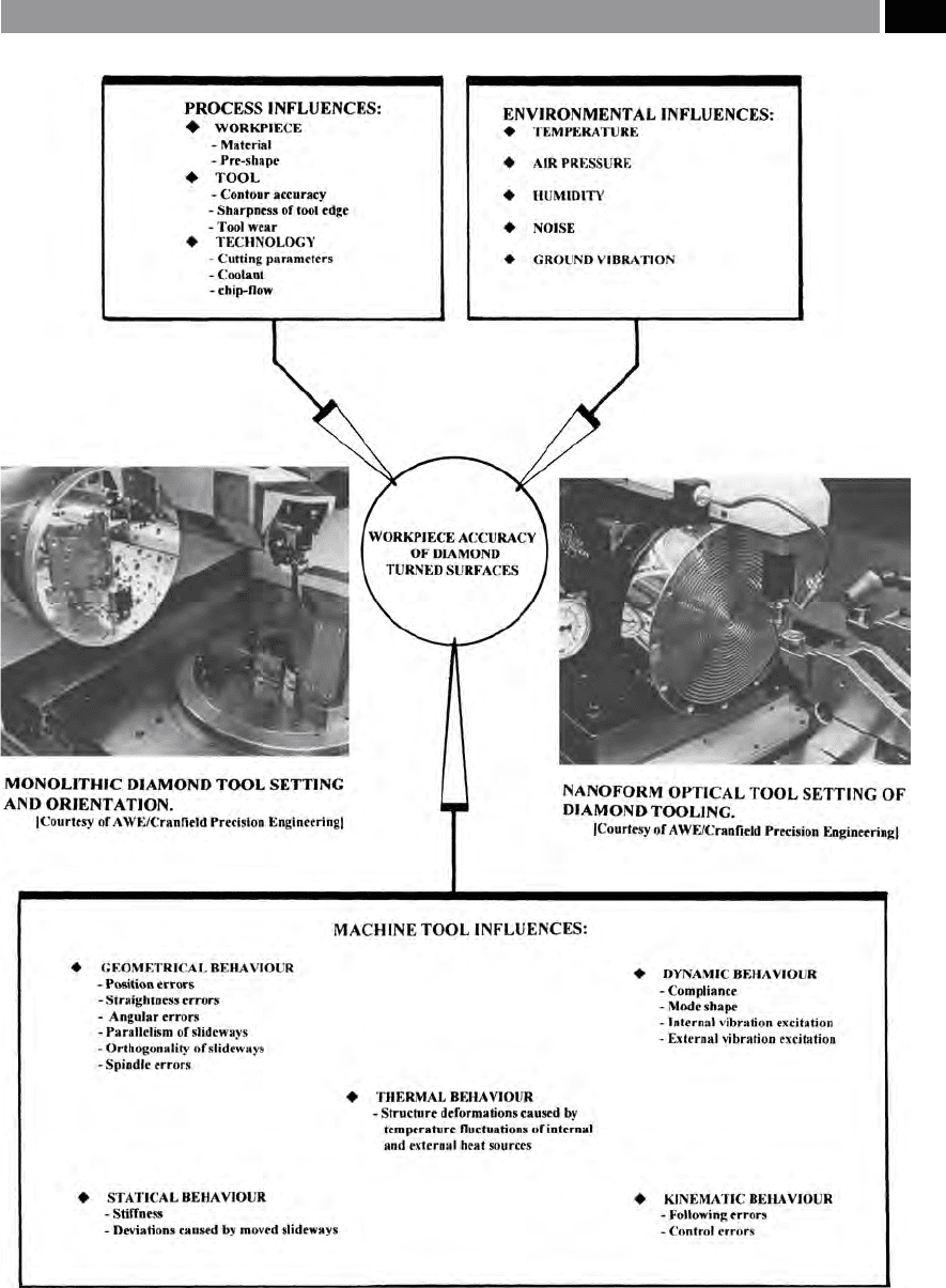
Figure 256. The error sources from the processes; environment and machine tool; on workpiece accuracy. [Source: Breuck-
mann & Langenbeck, 1989]
.
Machining and Monitoring Strategies 527

tioned, ultra-precision machining does not usually en-
tail machining very diminutive components, but it is
normally concerned with holding exceptionally tight
tolerances on macro-sized parts (Fig. 257b). In fact, a
diamond turning machine tool that can manufacture
components to nano-tolerances is depicted in Fig.
257a. is ultra-precision CNC lathe is considered to
be the most accurate and precise machine of its type
currently available. erefore, it is worth discussing
the machine and its environment, as its installation
and operation encapsulates all of the error sources
shown in Fig. 256.
Nano-Machine Tool and its Facilities
In Fig. 257a, is shown a very expensive and highly
sophisticated machine tool, it was delivered to the
Atomic Weapons Establishment (Aldermaston, UK)
from the manufacturers Craneld Precision Engi-
neering (UK). Its intended purpose was to machine
Perspex optics and large thin-walled aspheric shells
h
aving form errors of <5 µm, together with wafer-thin
laser targets having micro-machined features, but held
t
o tolerances of ± 10 nm, by single-crystal (monolithic)
diamond tools – these diamond cutting edges being
orientated along their correct crystallographic plane,
allowing turned surface texture values (Ra)
of <1 nm
to be achieved.
If an ultra-precision machine tool is required to
work at nanometric resolution, then if it needs to be
located within a manufacturing plant, the machine
tool must have a special-purpose facility designed,
constructed and built to exceptionally-stringent
and specied requirements. Prior to discussing this
facility, it is worth describing some features of this a
machine tool, so that one can comprehend the signi-
cant technical problems that had to be overcome, in
order for it to achieve a ‘true’ nano-machining capabil-
ity.
e machine tool was constructed on a polymer
concrete base, that consisted of 8 tonnes of synthetic
granite, giving the desirable properties of: excellent
thermal stability; high stiness; plus good vibration
damping characteristics. Strangely for a diamond
turning machine, the headstock was equipped with a
hybrid hydraulic/air spindle rather than an air-bear-
ing design, because this spindle’s specially-designed
construction enabled an increased load-carrying ca-
pacity (57 kg), coupled to superior stiness. Spindle
s
peed range was from: 200 to 5,000 rev min
–1
. ree-
axes were tted, two linear axes – running on fully-
constrained hydrostatic dovetail bearings with linear
m
otor drives and one rotational axis. ese axes kine-
matics were: X-axis (520 mm); Z-axis (220 mm); B-
axis (360°) – as illustrated in Fig. 256-middle le. A la-
ser-positioning system was tted to the axes, having a
resolution of 1.25 nano-metres, incorporating a wave-
length tracker, to compensate for any environmental
changes to the air: temperature; pressure; humidity;
hydrocarbon content; etc. e CNC controller utilised
a
high resolution (1 nm) fast feed-forward operation,
thereby reducing servo-following errors, combined
with real-time axis compensation together with a
two-dimensional error compensation capability – for
straightness and orthogonality.
Tool-setting errors on the monolithic diamond
tooling, were minimised by a unique probe and optical
s
etting technique (Fig. 256 – middle-right), reducing
form errors, when utilising the rotational B-axis for
spherical/aspherical turned component geometry
72
.
e nanocentre machine tool, was housed in a tem-
perature-controlled environmental enclosure, consist-
i
ng of the temperature being held at: 20°C ± 0.5°C, en-
c
losed within 100 mm thick high density polyurethane
foam panelling – providing high thermal resistance,
with an air-tight seal. e positive-pressure air-supply
unit was situated outside – in an adjoining plant room,
ducted into the enclosure by dra-free ducts, with ten
platinum resistance temperature probes (i.e. resolu-
tion 0.001°C) strategically situated within the volume
space, continually monitoring the enclosure’s temper-
ature. Lighting from the uorescent lights had their
chokes removed from the enclosure, thereby reducing
the localised air temperature ‘stratication eects’ by
72 ‘Form errors’ , the principal causes of form error when spheri-
cal/aspherical diamond turning components, can be sum-
marised in the following manner:
Conical error – due to spindle misalignment,
Chevron and Ogive errors* – due to rst-order tool wear
and centring errors,Waviness error – resulting from sub-
strate vibration and tool prole error,
Astigmatism – created by the component xturing arrange-
ments and material stiness.
*Chevron error occurs when turning a convex spherical formed
component – due to the tool ‘over-shooting’ , while, an Ogive
error results from the tool stopping short – this latter error
creating an ‘ogival arch eect’ , with both these prole errors
being due to an incorrect tool centre height setup.(Sources:
Myler and Page, 1988; Wheeler, 2001)
–
–
–
528 Chapter 9
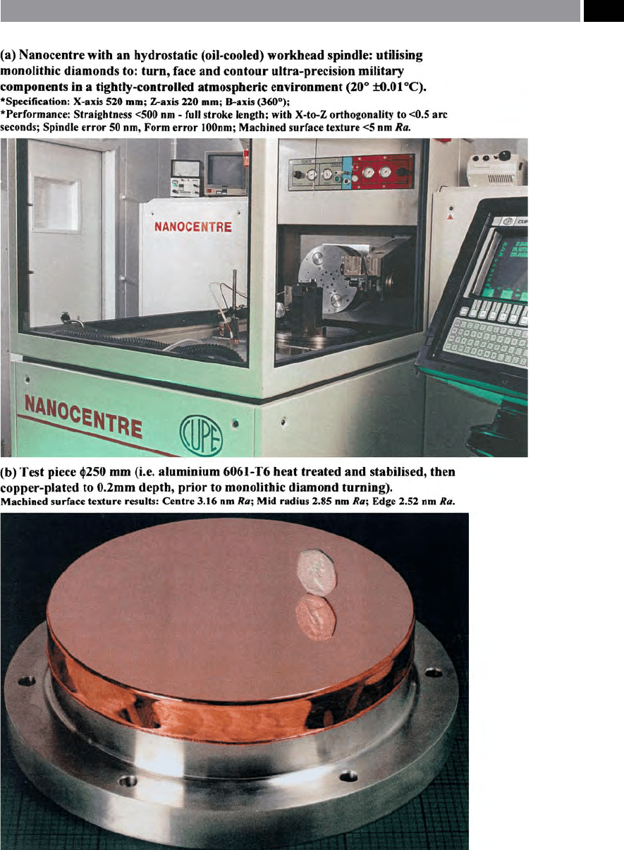
Figure 257. Nanometric machining to ultra-precise dimensional and surface texture characteristics. [Source:
Lamb & Gull, 1999]
.
Machining and Monitoring Strategies 529

over 1°C. e hydraulic and electronic cabinets were
temperature – controlled to ± 1°C. e ‘refractive index
of the air’ had to be corrected – based upon a modi-
cation to the Edlen (1966) equation, as the laser path
positional monitoring system would otherwise be af-
fected, with a correction factor being entered into the
CNC controller.
e ‘T-shaped base’ of the Nanocentre was sup-
ported on three pneumatic mounts that were ‘tuned’ to
e
liminate oor-borne vibrations of ≥ 2.5 Hz. Two types
of vibrational sources occur, namely forced- and self-
excited, with the forced vibrations originating from
external sources – through the foundations, while the
self-excited vibrations normally being the result of in-
ternal sources. A ‘oor vibration audit’ on the vibra-
tional inuences was conducted, to establish whether
the overall enclosure was suciently vibration absor-
bent. e oor vibration spectra gave typical vibra-
t
ional readings of 1 nm (rms) at frequencies of 25 Hz,
during the tests, with the external air compressors
e
mitting a oor borne 25 Hz frequency component,
which had to be subsequently nullied. Further testing
procedures were undertaken, including ‘modal analy-
sis’ and ‘thermal imaging’ of the machine’s structure,
together with a full calibration of the machine tool’s
kinematics.
Once all of these tests and various others had been
completed and compensated for, then a machining
testing program could then be undertaken. A typi-
cal test piece is illustrated in Fig. 257b, where an al-
uminium 6061-T6 part was heat treated and then
stabilised, of φ2
50 mm copper-plated (200 µm depth
coating) part. ese testpieces were faced-o with a
monolithic diamond tool – taking very shallow D
OC
’s
of just a few micrometres, producing for example, a
f
ace-turned surface texture averaging ≈ 2.8 nm Ra.
Later, proling tests were also conducted, prior to -
nal operational acceptance by AWE, from the machine
tool builder.
Prior to completing this summation of the just
some of the rigorous testing procedures carried out to
ensure that the Nanocentre machine tool could oper-
ate within the nanometric range of ultra-high machin-
ing operation, it is worth making an unusual point
concerning human intervention at this exacting-level
of machining. It was found that when several person-
nel were within the machine tool enclosure while
machining took place, then the thermal output from
these people, inuenced the part’s dimensional size
– without actually contacting the machine, by simply
acting as a heat-emitting source
73
. Moreover, it was
also found that when diamond-turning
74
by facing-o
a very ductile testpiece similar to that depicted in Fig.
257b, when these people were in conversation during
the nanometric cutting of the part, their ‘voice signa-
tures’ – in the form of air-borne vibrations were ‘ma-
chined’ into the surface – in a similar manner to that of
an acrylic recording of a record in the past! erefore,
in order to ensure that both the human thermal eects
and the vibrational perturbations (i.e. by air-borne vi-
brations – talking), the personnel had to be removed
while any ultra-precision machining operations were
in progress.
Ultra-precision machining at these nano-metric
levels of operation, severely stretches today’s levels
of technological challenges for: machine tools, me-
trology, plant and equipment, as we approach that of
atomic-levels of precisional uncertainties
75
. It is not
just the case of purchasing an extremely accurate and
73 ‘Human body – as a heat source’. e average body – in a
‘sedentary state’ , will emit ≈100 W of heat. So, here in this
case, when there are two people present in the machine tool
enclosure, they will radiate ≈200 W of heat – inuencing
the machine’s and hence, the workpiece’s thermal expansion
– when machining at nanometric levels of accuracy and preci-
sion. (Internet source: Burruss, R.A.P., Virtual People, 2005)
74 ‘Monolithic diamond’ ,
has some of the following characteris-
tics: hardness of ≈8,000 Hv; Density (ρ) of 3,515 kg m
–3
; com-
pressive strength of 7,000 MPa; and a Young’s modulus (E) of
930 GPa.(Source: Cardarelli et al., 2000)
75 ‘Atomic radius’ ,
for example, for some typical elements, ranges
from that of: carbon, having an atomic radius of ≈0.071 nm
(i.e. its atomic ≈φ0.142 nm)*, iron’s atomic radius is ≈0.124 nm
(i.e. ≈φ0.248 nm, or ≈¼ nm)*, Aluminium’s atomic radius is
≈0.143 nm (i.e ≈φ0.286 nm, or >¼ nm), Cesium’s atomic radius
is ≈0.265 nm (i.e ≈φ0.530 nm, or >½ nm).(Source: Callister, Jr.
et al., 2003)*Slight digression here, may help explain why these
atomic radii are important, when certain elements are alloyed
together, such as iron and carbon, these being the main con-
stituents of plain carbon steel.When an allotropic change oc-
curs to the iron’s atomic lattice structure (i.e. BCC→FCC @
≈910°C), then the carbon being somewhat smaller, can t into
these (now) larger interstitial sites – voids – within the FCC
iron lattice – distorting the adjacent iron atoms. Upon rapid
cooling (e.g. by water quenching), some of the carbon is
‘trapped’ and severely distorts the structure as it attempts to
transform back to the original BCC form. Hence, this dis-
torted structure of iron-carbon – termed martensite, is both
a very hard, but brittle structure, requiring tempering: if it is
to act as a hardened and tempered workpiece material. is is
the basis (i.e. somewhat simplied), behind this iron-carbon
heat-treatment process.
530 Chapter 9

precise machine tool (Fig. 257a), and hoping to utilise
it to machine when approaching nano-metric resolu-
tion levels. ere are many oen interrelated factors
that have to be considered and then dealt with, if one
is to successfully operate at this ultra-precision level of
machining operations.
9.11 Machine Tool
Monitoring Techniques
Introduction
One of the most fundamental requirements for increas-
ing productivity of CNC machine tools, is the ability
to operate them ideally, in an untended manner, but
at the very least, minimally-manned – whether they
are ‘stand-alone’ machines, or part of a exible manu-
facturing cell, or system (FMC/S). So, if an untended
operation has been decided upon, then the absence
of an operator will create a considerable number of
problems that must be overcome, if the machining op-
erations are to be satisfactory. ese problems arise in
performing the monitoring and service functions that
are usually seen by the operator, who would normally
undertake the: monitoring of the cutting tool’s condi-
tion and its performance; replacing worn, or defective
tooling by interrupting the cutting cycle; assessing the
workpiece quality during machining; changing speeds
and feeds – if required; plus responding to unusual
conditions that are either seen, or heard, during the
cutting operation. While, in an unmanned machin-
ing environment, the associated monitoring systems
must provide the ‘articial intelligence’ (AI), necessary
to ‘mirror’ the experience gained by a fully-skilled op-
erator and their instinctive reactions and, to provide
the type of expertise usually associated with human
involvement. To cope with these every-day human-
intelligence activities and their subsequent interven-
tion during any machining operations, a considerable
number of monitoring systems have been developed.
In general, monitoring systems can be classied as:
process-monitoring; workpiece-monitoring; machine
tool monitoring; and tool-monitoring systems. Typical
applications of these monitoring systems for untended
operation on machine tools, include:
•
Monitoring the correct loading of the workpiece,
correcting any set-up misalignments, or datum o-
sets, while checking the quality of the workpiece,
•
Checking that the correct tools are available, by
identifying both the tools and their setting osets,
monitoring for tool wear and breakage and, initiat-
ing tool replacements – as necessary,
•
Adjusting speed and feed as appropriate and, com-
pensating for such eects as tool wear, thermal de-
formation and chip congestion,
•
Monitoring of machine elements, including the
CNC controller and taking any necessary correc-
tive action in response to: program failure; diag-
nostic error messages; etc.
Whatever the function that is to be monitored, there
is a need for some form of sensor to be incorporated
into the system – to detect any problems as they arise,
so that action can be appropriately taken, if necessary.
us, a sensor’s output – triggered by an error mes-
sage, must be processed to obtain the correct informa-
tion, allowing decision(s ) to be made. e machine’s
control unit, will then receive this ‘sensed’ result and
initiate controlled actions to either correct, or re-
cover the situation. Various types of monitoring and
sensing systems are currently available for machine
tools. Although, because this subject matter is so vast
and sophisticated, only several of these monitoring
techniques and sensing systems will now be consid-
ered.
9.11.1 Cutting Tool Condition
Monitoring
Introduction
Whenever an operator is present during a machining
operation, one of their major functions is to monitor
the tool’s condition while the cutting continues, where
they continually assure themselves that a tool in-cut
is performing productively. e tool-related monitor-
ing functions performed by an operator during any
component’s manufacture, may be classied into four
groups, briey these are:
1. Tool identication – this ensures that the correct
tool will be used for a specic operation, with a va-
riety of techniques being employed to achieve this
crucial tooling activity. Techniques include the use
of: touch-trigger probes (Fig. 133); non-contacting
probing methods (Fig. 134); ‘tagged’ tooling of the
contact (Figs. 116 and 117), or non-contact variet-
ies (not depicted),
Machining and Monitoring Strategies 531

2. Tool-oset measurement – of the cutting edge’s po-
sition is necessary, in relation to that of the part’s
datum point. is can be accomplished by the
‘probing-techniques’ and tool identication meth-
ods mentioned above,
3
. Tool life monitoring – is necessary to estimate the
extent of a worn tool’s condition, which must be
replaced prior to tool failure. e are a range of
sensing devices available and they can be classied
into two main groups: ‘Direct sensing’ – include:
radioactive techniques; measurement of electrical
resistance; optical observation of the wear zone;
m
easurement of workpiece dimensional changes;
or the distance between the workpiece and the
tool post, ‘Indirect sensing’ – based upon either:
temperature; sound; vibration; acoustic emission
and force. is latter method can be measured
and monitored either directly, by dynamometry
(Figs. 178–180, 237 and 244), or indirectly via mea-
surements of power, current, or torque – some of
these techniques will shortly be discussed,
4
. Tool breakage detection – can be monitored to en-
sure that the cutting edge does not fail in-cut, as
damage to both the tooling assembly and the work-
piece may occur as a result. Once again, a variety
of commercially-available techniques based upon
force-related signals are available, including: those
methods that use a dynamometer, either situated
on the tool block, or in say, a turning operation be-
low the tooling turret (Fig. 179); thrust-/feed-force
sensors (Fig. 258); spindle-bearing/motor-current
monitoring (not shown); power-/torque monitor-
ing (Fig. 259a). is latter technique (Fig. 259a),
is oen known as: ‘Torque-controlled machining’
(TCM).
NB I
n order to fully appreciate the complexity and
sophistication of any tool- condition monitoring,
on CNC machine tools, the following section has
been included.
Tool-Condition Monitoring –
With Feed-Force Sensors
Modern microprocessor-designed tool-monitoring
systems can be utilised for a variety of reasons, for
example, to monitor the tool’s condition, or to reduce
machining value-added costs. e advantages of using
monitoring detection, are
•
Tool wear is monitored and tool changes initiated
when necessary, so avoiding damage to the ma-
chine, or workpiece,
•
If breakage occurs, a signal will be immediately
produced to stop the machine tool – usually within
milliseconds,
•
e system detects if a tool, or workpiece is miss-
ing, thus eliminating wasted machine time and the
likelihood of unpredictable crashes.
While the cost advantages of using tool monitoring
are:
•
Tool life can be optimised, meaning that the tools
need to be only changed when they are worn – to a
specied amount (Figs. 174 and 176) and so reduce
the tool costs (Fig. 177e),
•
Down-time (i.e. here, it is normally associated with
unanticipated wear rates, or tool crashes) is re-
duced, which increases the machine’s output and as
a result, improving cycle-time and costs per part,
•
Repairs to the machine tool and cutting tools may
be reduced to a minimum, so the maintenance costs
are lower,
•
e machining operation is automatically moni-
tored, limiting any costly labour rates by subse-
quent operator involvement.
e above listed advantages for tool-condition moni-
toring are quite an impressive recommendation, but
how does it achieve consistent and accurate tool moni-
toring, while simultaneously controlling the cutting
process? ese questions will now be considered, deal-
ing in the rst instance, with how the system monitors
the tool’s performance during machining.
A
well known fact is that a tool will produce rela-
tively high loads during a cutting operation, as it
begins to wear. For eective ‘process monitoring’ it
is important that the signal utilised should vary in a
progressive manner as the tool wears and, not just at
the time that it actually breaks. It has been shown (Fig.
258b) that during a machining operation, the axial
force component (F
A
) provides a better indication of
the cutting edge’s condition as a function of tool wear,
than the torque value (M). us, the increase in the
axial force is more clearly dened – in both cases, from
t
hat of a sharp tool (Fig. 258b – le) to that of a worn
tool (Fig. 258b – right). is change in the force gener-
ated whilst cutting is instantly detected by a feed force
sensor (Fig. 258a). e sensor transforms the force
change into an electrical signal which is transmitted
532 Chapter 9