Smith G.T. Cutting Tool Technology: Industrial Handbook
Подождите немного. Документ загружается.

6.1 Modular Quick-Change
Tooling
Introduction
e modular tooling concept was developed by cut-
ting tool manufacturers from the long-standing tool-
ing cartridges (Fig. 112 – indicates a typical self-con-
tained cartridge), which had been previously available
for many years. Initially, the modular tooling was de-
signed and developed for turning operations (Fig. 113)
and was demonstrably shown to oer amazing versa-
tility to a whole range of machine tools and, not just
the CNC versions.
e point that the tooling is a key element in the
whole manufacturing process was not lost when in the
early 1980’s the United States Government commis-
sioned a ‘Machine Tool Task Force Survey’ on machine
tools and tooling, to determine the their actual utilisa-
tion level. Here, the US ndings compared favourably
with a similar survey undertaken in Germany some
years later. It was a surprising fact that on average
only between 700 to 800 hours per annum, were spent
actually ‘adding-value’ by machining operations on
components. is particular outcome becomes even
more bizarre, when one considers that the theoreti-
cally available annual loading time for a machine tool
of 364 days x 24 hours per day yielded a potential ma-
chine tool availability of 8736 hours – representing a
meagre ≈8% as actual cutting time. is ≈8% value is
shown on the diagram in Fig. 114a, where an attempt
has been made to identify and show actual individual
blocks of time allocated to both shi-wastage and non-
productive time. is massive potential machine tool
availability, is further compounded when one consid-
ers the rapid advances in both machine and cutting
tool developments of late (Fig. 114b), where tool utili-
sation time and in particular the lead-times would sig-
nicantly benet from using a modular quick-change
tooling strategy.
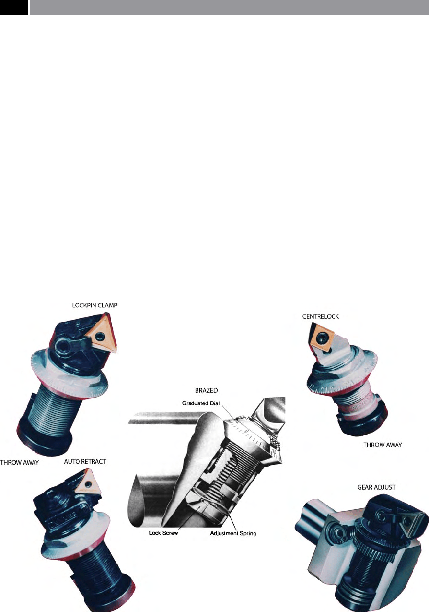
Figure 112. Microbore (adjustable) modular cartridges, with indexable inserts. [Courtesy of Microbore Tooling Systems].
212 Chapter 6
Prior to a discussion of ‘modular tooling concepts’ ,
it is worth briey mentioning that in many instances,
conventional tooling correctly applied can make sig-
nicant productivity savings, whether the emphasis is
on increased production – through longer tool life, or
on a reduction in the cycle time for each part. e ma-
chining trend in recent times, has been to increase the
productive cutting time of expensive machine tools
and, in order to achieve this objective it is necessary to
minimise tool-related down-time.
Cutting tool manufacturers have not been slow
in developing and producing modular quick-change
tooling systems. eir initial steps into such systems
occurred in the early 1970’s, with one solution involv-
ing changing the indexable insert itself: the major
drawback here was that the insert-changer was com-
plex in design and could only change one type of in-
sert. is fact limited it to long-running turning ap-
plications and even here, it suered with the advent
of CNC. Yet other approaches involved changing both
the tool and its toolholder, in a similar manner to cur-
rent practice on CNC machining centres. is sys-
tem also imposed restrictions, owing to the relatively
high weight and dimensional size of the tool-changer,
which meant that its load-carrying capacity was lim-
ited. Even where a tool magazine is present – such as
is found on certain types of turning and machining
centres, its capacity becomes rapidly exhausted, so
that fully-automated operation over a prolonged pe-
riod is not possible. Further, the multitude of geom-
etries and clamping systems necessary, causes impos-
sible demands on an automatic tool-changer, with the
problem being exacerbated still further by the fact that
indexable inserts may not be suitable for all machining
operations. erefore, a completely dierent approach
was necessary for automatic tool-changing systems, to
overcome these disadvantages.
Prior to a discussion concerning modular quick-
change systems in use today, it is worth mentioning
t
hat many machine tool manufacturers can oer extra
capacity tool magazines, holding almost 300 tools – in
certain instances (Fig. 115). So the question could
rightly be asked: ‘Who needs such modular quick-
change tooling, when machines can be provided with
their own in-built storage and tool-transfer systems?’
is is a valid point, but a very high capital outlay is
necessary for these extra-large magazines (i.e. as de-
picted in Fig. 115) and, even then, only a nite tooling
capacity can be accommodated and its variety would
be considerably reduced if a ‘sister tooling’
1
approach
1 ‘Sister tooling’ – is where there is at least one duplication of
the most heavily-utilised tools within the tooling magazine/
turret. is multiple-loading of duplicate tooling, is normally
operated as follows: once the rst tool of the duplicates is near-
ing the end of its active cutting life, it is exchanged for a ‘sister
tool’ and will not be called-up again during the unmanned
production cycle. is duplication strategy, can signicantly
extend the untended machining environment, through per-
haps, a ‘lights-out’ night-shi, if necessary.
NB It is important to establish the anticipated tool life for
a tool (i.e. by perhaps utilising a simplied Taylor’s tool-life
equation , or maybe from previous machining trials – more
on this subject later), as its in-cut time. is value can be input
into many of today’s CNC tool tables (i.e. in terms of minutes
available of G-codes feeds, for example: G01, G02, G03, etc.).
As these G-codes feed along and around the components ge-
ometry producing parts, the time is decremented down, until
the available cutting time approaches zero, then its duplicate
‘sister tool’ is called-up from the tool table, and hence it is
transferred to the spindle (i.e. having previously taken out the
‘old tool’) from its location in the magazine and, in this man-
ner minimising machine tool down-time.
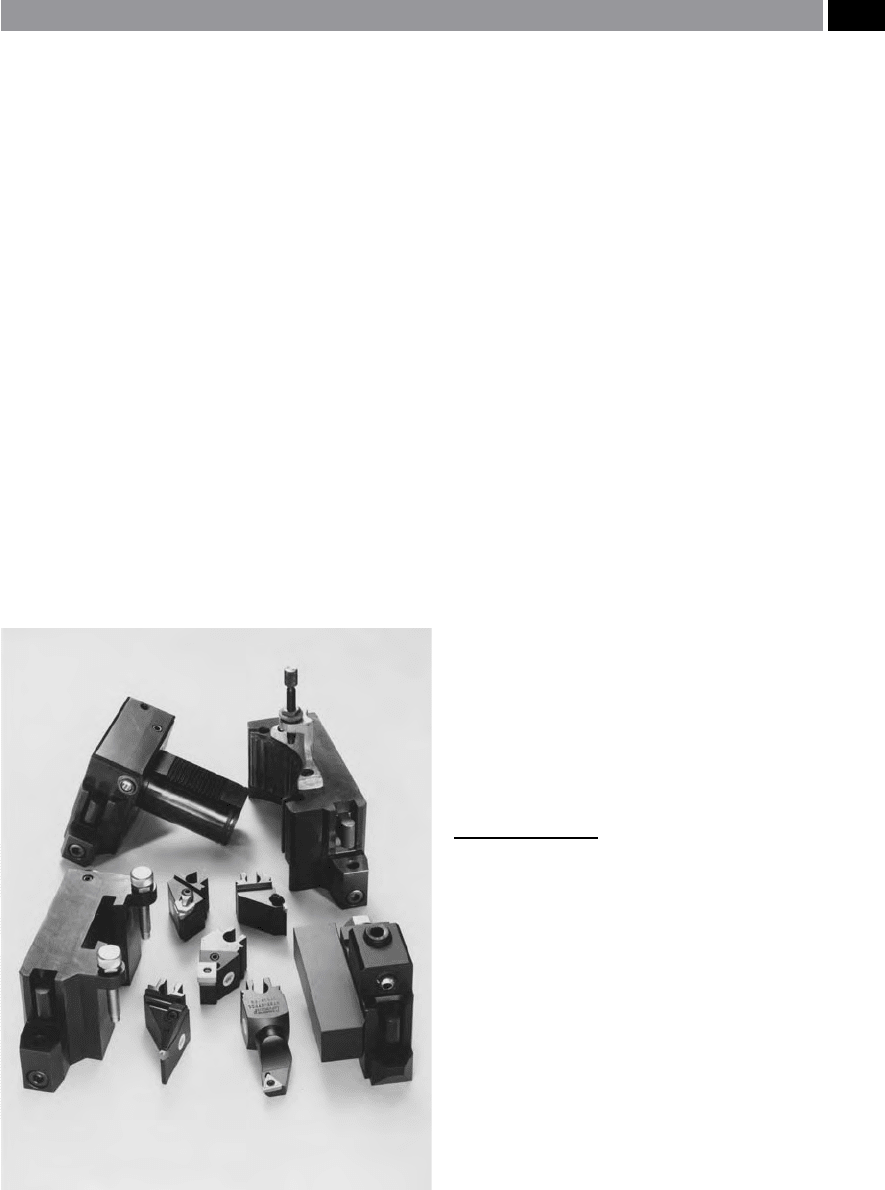
Figure 113. The original ‘modular tooling concept’, termed
the block tooling system – allowing ecient and fast ‘qualied’
tooling set-ups for non-rotating tooling on both conventional
lathes and turning centres. [Courtesy of Sandvik Coromant]
.
Modular Tooling and Tool Management 213
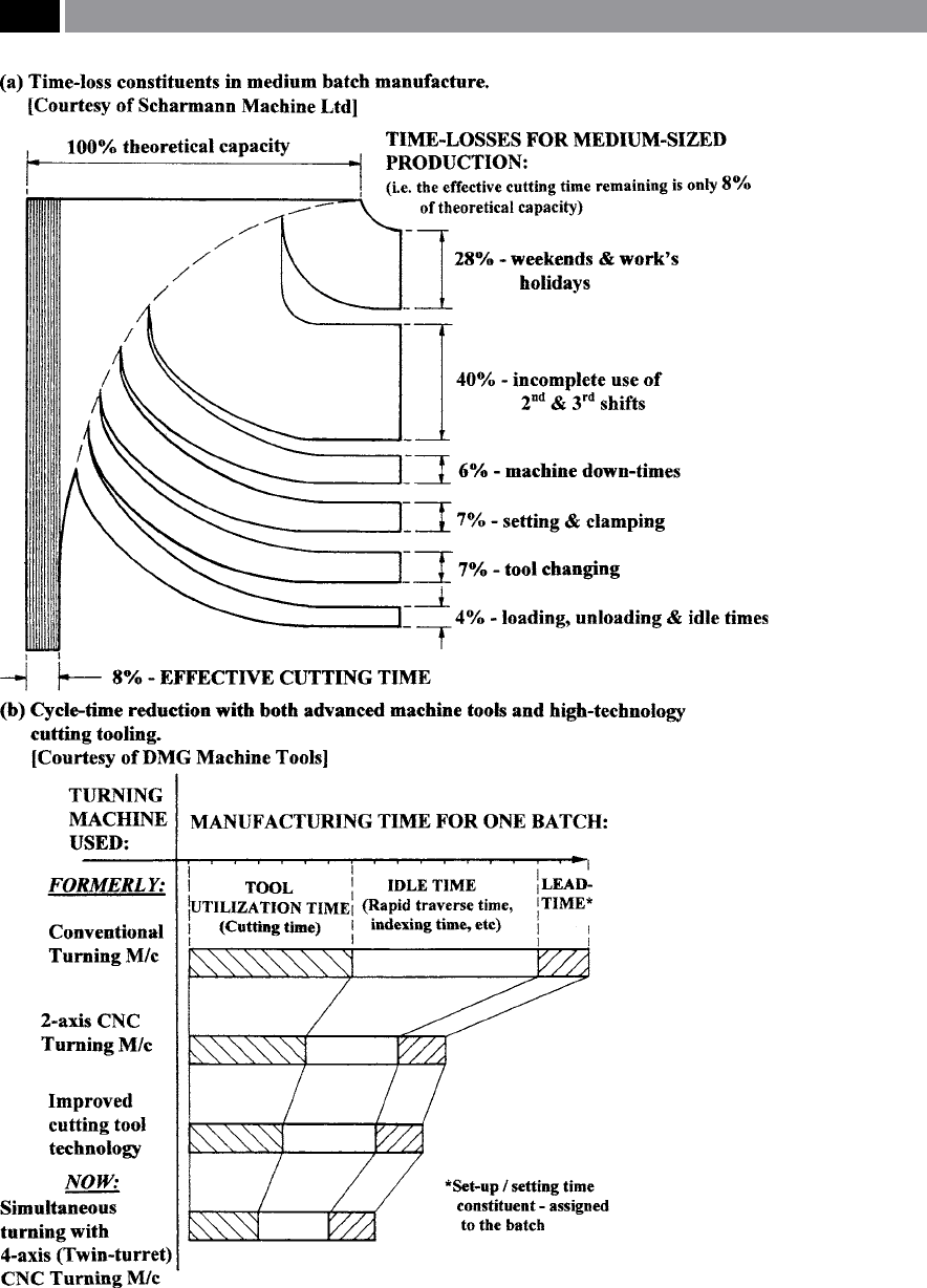
Figure 114. Cutting availability and cycle times can be dramatically improved with ecient tooling strategies..
214 Chapter 6
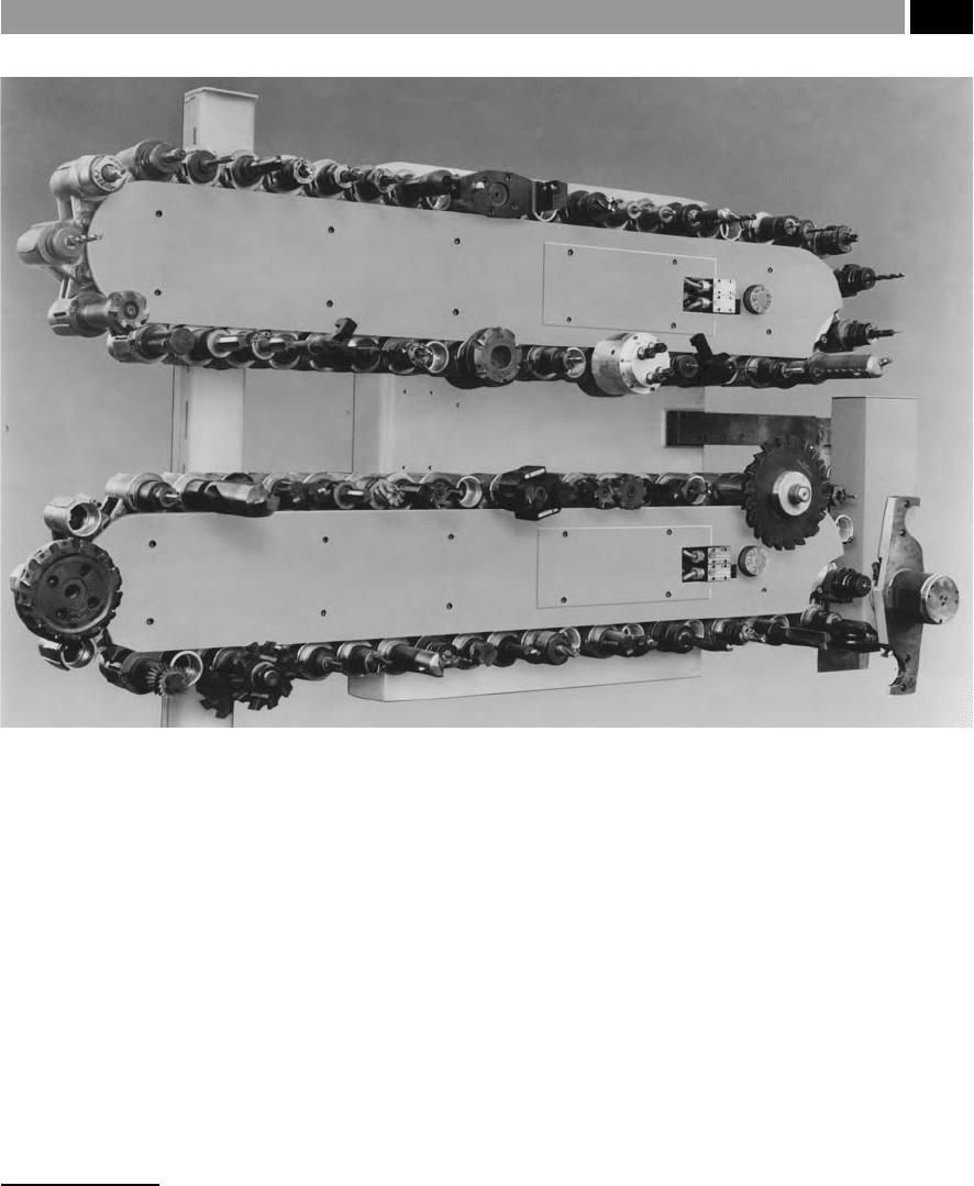
was adopted. is tooling-capacity problem becomes
acute in the case of Fig. 115, where some large tools
have to be held in the magazine and empty tool pock-
ets have to le either side of it – as shown by the large
tool situated on the lower chain on the extreme le.
Machine tool builders have spent considerable time
and eort on reductions in the non-productive activi-
ties, such as ‘
cut-to-cut times’
2
. Modular quick-change
tooling will further reduce set-up times and for any
2 ‘Cut-to-cut times’ , having reductions in tool transfer on: turn-
ing centres – with bi-directional turret rotation, or on ma-
chining- and mill/turn-centres equipped with either tool car-
ousels/magazines, enabling rotational indexing to the correct
tool pocket, prior to load/unload of tooling, tool transfer – re-
ducing the idle-times to the next machining operation to just
a few seconds. If the machine has facility for either automatic
jaw-changing on a say, a mill/turn centre, or pallets on a ma-
chining centre, this non-productive operation is undertaken
simultaneously with the tool-changing/ tool-indexing – on the
latest machine tools, thereby further reducing idle times.
subsequent tool maintenance activities, more will be
said on the topic later in this chapter under the guise
of ‘tool management’.
So far, these introductory remarks have addressed
some of the issues concerning early techniques for
quick-change tooling and the machine tool builder’s
approach to overcoming the problem. So again, one
can state: ‘Why does one need modular quick-change
tooling?’ One of the most important aspects of utilising
such tooling systems on for example, machining cen-
tres, has been to standardise and thereby reduce tooling
inventories (i.e. rationalise and consolidate the remain-
ing tools), whilst simultaneously giving the tools more
exibility in their cutting requirements which occur
during a production run. Now that many turning cen-
tres are equipped with full C-axis headstock control –
for contouring capabilities, together with driven/live
tooling from their turret pockets (i.e. termed: mill/
turn centres), their requirements for modular tooling
are similar to those of a machining centre.
From the previous discussion, it is now evident that
signicant reductions in the machine tool’s non-pro-
Figure 115. A 90-tool capacity, auto-toolchanger magazine (chain-type), three such magazines can be slotted together, to give
a 270-tool capacity. [Courtesy of Cincinnati Machines]
.
Modular Tooling and Tool Management 215

ductive times can be accomplished, by minimising the
down-time associated with utilising cutting tools. If a
manufacturing company incorporates modular quick-
change tooling systems on its machining and turning
centres, or even on some conventional machine tools –
involved in large batch runs, then great productivity
benets will accrue over a relatively short pay-back
period. is will be the theme for the discussion over
the next sections. Firstly, we will consider the tooling
requirements for turning centres and secondly, the ap-
plications for modular quick-change tooling on ma-
chining centres.
6.2 Tooling Requirements
for Turning Centres
Perhaps of all the machine tools that use either single-,
or multi-point cutters, the turning centre has under-
gone the greatest changes. e vast spectrum of these
turning-based machine tools, include at the one end:
basic CNC lathes – oen equipped with conventional
square-shanked toolholders and round-shanked bor-
ing bars, that are manually-loaded, to highly sophis-
ticated co-axial spindled twin-turret mill/turn cen-
tres. ese highly productive multi-axis machine
tools, have features such as: full C-axis control – for
part contouring; robot/gantry part-loaders – for e-
cient load/unload operations; automatic jaw-changers
for exible component work-holding; programmable
steadies – for supporting long and slender parts; tool-
probing systems – having the ability to apply automatic
tool oset adjustment with the capabilities of tool-wear
sensing/monitoring and control; work-probing inspec-
tion – for automated work-gauging of the workpiece’s
critical features. With respect to these latter multi-axis
highly-productive machine tools, the capital outlay
for them is considerable and in order to recoup the
nancial outlay and indeed, cover the hourly cost of
running such equipment, they must not only increase
productive cutting time – with an attendant reduction
in cycle times, while simultaneously reducing any di-
rect labour costs associated with the machine’s initial
set-up and maintenance. It is oen this nal aspect of
labour-cost reduction, which becomes the most at-
tractive cost-saving factor, as it is usually constitutes a
large component in the overall production cost in any
manufacturing facility.
When a company species a new turning centre for
its production needs, they might want to increase its
versatility by specifying a rotating tooling with a full
C-axis capability, giving the ability to not only con-
tour-mill part features (i.e. see Fig. 93), but cross-drill
and tap holes while in-situ – termed ‘one-hit machin-
ing’. ese secondary machining operations may even
eliminate the need for any post-turning machining
operations, on for example, a machining centre, giv-
ing yet further savings in production time – work-in-
progress (WIP) and minimising the need for an addi-
tional machine tool. If oor-space is at a premium, then
one highly productive and sophisticated multi-axis
mill/turn centre, may be the solution to this problem.
Previously, justication for the need to employ a
modular quick-change tooling strategy for turning
centres has been made. Some of these modular tooling
systems will now be reviewed, many of which are now
being phased-out, while others have recently become
popular. Basically, there are two types of modular
quick-change tools available today, these being catego-
rised as follows: Cutting-unit systems, or Tool adaptor
systems. e two systems vary in their basic approach
to the quick-change tooling philosophy and, whether
they are designed to be utilised on turning, or machin-
ing centres separately, or alternatively, for a more
universal approach. e cutting-unit system was one
of the rst to be developed by a leading cutting tool
manufacturer and is universally known as the ‘Block
tool system’ (Fig. 113, 116 to 118). is system (Fig.
113), is based on a replaceable cutting unit (i.e. ‘club
head’) utilising a square-shanked toolholder, with the
coupling providing a radial repeatability to within
±0
.002 mm. is high-level of repeatability to ± 2 µm, is
necessary in order to minimise the coupling’s eect on
the diameter to be turned. To ensure that the generated
c
utting forces do not deect the ‘Block tool’ , a clamp-
i
ng force of 25 kN is used. ‘Club head’ clamping may be
achieved in a number of ways, either: manually – with
an Allen key, or either by semi-automatic clamping, or
automatically, as depicted in Fig. 118. e clamping
force is normally provided by using a certain number
of spring-washers, these being pre-loaded to provide a
reliable clamping force. ese cutting units can be re-
leased by compressing the washers so that the draw-bar
can move forward. In the case of the automated cutting
unit system, a small hydraulic cylinder mounted on
the carriage behind the turret causes the draw-bar to
release it, this being timely-activated by a command at
the correct sequence within CNC program.
216 Chapter 6
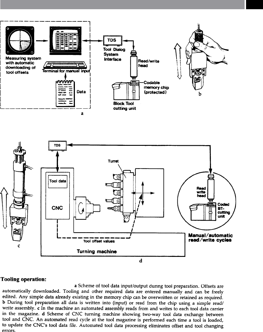
Figure 116. Tool data processing employing modular quick-change tooling on a turning centre, via the ‘intelligent/
tagget’ tooling concept. [Courtesy of Sandvik Coromant]
.
Modular Tooling and Tool Management 217

Previously, mention was made of the cutting unit’s
repeatability and its associated clamping forces, to-
gether with techniques for releasing the ‘Block tool’.
Now, consideration will be given to how the cutting
units are precisely located in their respective toolhold-
ers. e ‘Block tool’ is located in the following manner:
the cutting unit slips in from above the coupling (i.e. of
the receiving toolholder) to rmly rest on a supporting
face situated at the bottom of the clamping device.
is tool ledge supports the cutting unit tangentially
during the machining operation. Once the cutting
unit is seated on the bottom face (i.e. tool ledge), the
draw-bar is activated – either manually – with a key,
or by the hydraulic unit – in the case of automatic
cutting unit loading. is draw-bar activation, pro-
vides a rigid and stable coupling, that can withstand
the loads produced during cutting. Both internal and
external machining cutting units (Fig. 113) can be
supported.
A major advantage of all modular quick-change
systems is ease and speed of tool-changing, produc-
ing shorter cut-to-cut times, in comparison to that of
conventional tooling. If an operator is present whilst
machining, the added bonus here is one of reduced
operator-fatigue, since tool handling – particularly
with heavy tools – can be minimised particularly when
using either semi-automatic, or automatic tool-chang-
ing methods. As a result of the smaller physical size of
these modular tools, they can be more readily stored
in a systematic ‘tool-management’ manner, allowing
them to be eciently located and retrieved from the
stores, with the added bonus of reducing tool-stock
space.
e benet of just using the ‘entry-level’ manual
‘Block tool’ system over conventional toolholders, may
be gleaned from the following tabulated example, de-
picted in Table 8, where the numerical values in the
table form the basis for the comparisons. e gures
in the le-hand column are typical for most two-axis
turning centres, where: manual tool-changing is em-
p
loyed, securing the tool in its pocket and maintenance
takes place.
is data can now be applied to the practical situ-
ation for an environment of mixed production con-
taining small batches of turned components, where
the actual cutting time represents 15% of the total
machine-shop time. If one assumes that an average of
30% of the tools needed measuring cuts (e.g. compo-
nent diameters to be machined and measured, then
these values input into the machine tool’s CNC con-
troller) and, that 200 set-ups were required per year
on the machine, necessitating some 1580 tool changes
during these tasks per year. So, under such production
parameters, the quantitative strategic benets of util-
ising the modular quick-change tooling system over
conventional tooling, are as follows:
•
Setting-up time – dierences would be:
15 × 200 = 3000 minutes per year,
•
Tool-changing time – dierences are:
2 × 1580 = 3160 minutes per year,
•
Measuring-cut times – dierences amount to:
1580/3 × 5 = 2630 minutes per year.
ese time-savings mean that a total dierence of
8790 minutes would be accrued, or 146 hours, which
equates to a saving of 18 working days. Hence, this
simple ‘Block tool’ system allows for a signicant in-
crease in available production time over this time-pe-
riod. Alternatively, this time-saving can be multiplied
by the machine’s running cost per hour, to further
reinforce the correctness of the decision to purchase a
quick-change tooling system, since it quickly builds-
up the pay-back on the initial investment for this type
of tooling strategy. e simple example given above,
clearly demonstrates the real benets of using a man-
ual quick-change tooling system, on either a conven-
tional lathe, or turning centre.
So far, the merits of utilising a quick-change tool-
ing system have been praised, but one might ask the
question: ‘What type of batch size can justify the -
nancial expense of using such a ‘Block tool’ system?’
To answer this, we will consider the two manufac-
turing extremes of both large-batch production and,
small-batch production usage – the latter using one-
os.
Table 8. Comparison between utilising conventional and
quick-change tooling
Operation: Conventional
toolholder:
Block tool
system:
Setting-up time 30 15
Tool-changing time 3 1
Measuring-cut time 5 0
NB A
ll times are in minutes.
.
218 Chapter 6
Today, large batches and even mass production
runs, are increasingly performed in ‘
linked’
3
turning
centres. e manufacturing objective here is to limit
operator involvement and for planned stoppages and
tool changing/setting to occur according to an organ-
ised pattern, so that they usually happen in between
shis, or at recognised scheduled stops in the produc-
tion schedule.
For example, utilising the ‘Block tool’ system al-
lows tool changes to be organised and made very ef-
cient, especially so when the tool changes are semi-
3 ‘Linked turning centre production’. Here, the emphasis is on
back-to-back turning centres equipped with automated work-
piece handling and process supervision equipment, allowing
parts to be loaded/unloaded between the so-called ‘exible
manufacturing cell’ (i.e. FMC). is manufacturing strategy
enables a relatively wide range of part mixes to be undertaken
oering high machine tool utilisation rates, but covering a
relatively small production area ‘footprint’.
automatic, or automatic in operation (Fig. 118). ese
modular quick-change cutting ‘club-heads’ are small,
light and easily organised for tool changing. More-
over, they can be preset outside the machine tool en-
vironment and as a result, their accuracy is assured by
the precise mechanical coupling to that of its mating
holder. It is also possible to give these ‘Block tool’ cut-
t
ing unit’s a degree of ‘intelligence’ , by an embedding
coded microchip, having a numbered tool data mem-
ory-coded identication – sometimes termed ‘Tagged-
tooling’. In the early days of tool read/write micro-
chips, they were of the ‘contact varieties’ (i.e. see Figs.
116 and 117), but many of today’s tool identication
systems are of the non-contact read/write versions.
Tool oset settings produced when initially measuring
them on the tool presetting machine, can have these
numerical values stored in coded information within
the in-situ micro-chip situated within the quick-
change tooling ‘club head’. An alternative approach to
actual measurement of the tool osets, is to utilise ei-
ther a touch-trigger, or non-contact probe, situated on
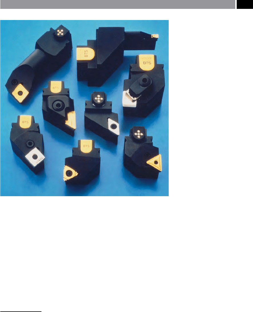
Figure 117. A few examples of
modular block tooling, some toolhold-
ers illustrating built-in memory-coded
tool identication chips. [Courtesy of
Sandvik Coromant]
.
Modular Tooling and Tool Management 219
the machine tool – more will be said on this subject
later in the chapter. ese tooling aids also minimise
the setter/operator activity and this will ensure that
such vital information is correctly performed, thereby
eliminating the risk of mistakes being made during
any hectic machine stoppages. While another bene-
t of using a quick-change modular tooling strategy,
is that the time needed to change tools is very short.
It may even be possible to make an unscheduled tool
change for critical tooling, if for example, their wear-
rate is unexpectedly high. is unscheduled tooling
adjustment, will raise the overall cutting performance,
which in turn leads to improved and economical tool
utilisation, particularly during a large production run.
Where a company is involved in large-batch, or mass-
production runs, its should be obvious by now, that
utilising modular quick-change tooling oers consid-
erable savings by reducing the non-productive cut-
ting times. is modular tooling strategy is also true,
but to a lesser degree, for either small batches and can
even be relevant in the extreme case for certain one-
os, requiring many tool changes in the machining of
a complex part geometry. is latter factor is particu-
larly the case when ‘p
art families’
4
are required to be
produced.
Frequently the problem that is present within a ma-
chine shop, is one of insucient tool storage on the
actual machine tool, this is particularly the case for
single-turret turning centres – having limited pockets
available for the tooling. Under such circumstances,
the solution may be to use modular quick-change tool-
ing. Using say, minimal levels of tooling automation,
via semi-automatic quick-change tooling, extends the
turret’s capacity with minimal loss of productive cut-
t
ing. Replacing a new cutting ‘club head’ , simply re-
quires the operator to li out the old unit and push
in another – at the press of the tool-release button.
4 ‘Part families’ , refer to the machining of components that
have either similar workpiece geometries – oen termed ‘as-
pect ratios’ , or comparable machining processes undertaken
to complete the parts.
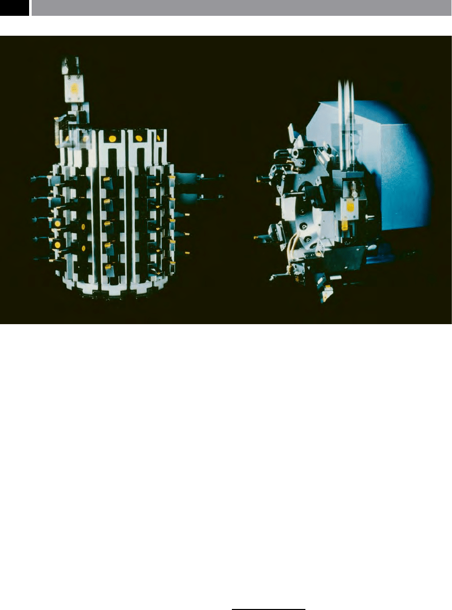
Figure 118. Automated gantry loading of modular block tooling from magazine to a turning centre’s turret. [Courtesy of Sandvik
Coromant]
.
220 Chapter 6

Optional tool stops can be programmed into the CNC
controller for just this purpose. By presetting the tool-
ing, in conjunction with each cutting head, the cou-
pling’s guaranteed repeatability, ensures that the cut-
ting edge is both accurately and precisely positioned
relative to the workpiece’s orientation and datum. is
fact, negates the need for the operator to have to in-
dividually adjust all of the tooling osets for dierent
workpiece congurations.
Yet another approach to the lock-up sequence and
design of modular quick-change tool adaptor systems,
is depicted in Fig. 119. e mechanical-locking in-
terface is via a Hirth gear-tooth coupling mechanism
5
.
is system oers both a high positioning accuracy in
combination with an almost perfect transmission of
the torque eects induced by the oset in cantilevered
turning and grooving tooling, whilst cutting. Clamp-
ing consists of draw-bar locking aer insertion of
the male and female gear teeth of the desired cutting
unit into the adaptor. ese changeable cutting units
also require accuracy and precision in the manufac-
ture, with their location and clamping being achieved
through axial movement of a draw-bar. e draw-bar
can be either manually, or automatically moved by us-
ing a torque motor. is draw-bar locating mechanism
allows both the male and female coupling ‘geared faces’
to be rmly locked and assembled together. e Hirth
g
ear-tooth coupling has a repeatability of <±0.002 mm,
with tooling system that can be mounted in either a:
disk, drum, row, at, or chain magazine. e Hirth
coupling has a standardised installation, with identi-
cal dimensions of φ40 and φ6
3 mm, for the tooling sys-
tem selected. ese modular cutting mechanical in-
terfaces are directly mated together, allowing internal
coolant ushing and as such with use, will not become
polluted during its lifetime’s operation. As with all of
these modular quick-change tools they can have their
tooling of internal, or external mounting (i.e. shown in
Fig. 119), and of dierent ‘hands’ in order to achieve
universal turning/grooving machining applications on
the widest variety of parts.
Despite all of this convincing evidence in favour
o
f such tooling, some pessimistic manufacturing en-
5 Hirth gear-tooth coupling mechanism, is a well known tried-
and-tested mechanical-interface, which is oen present on
rotary axes for machining centre pallets, allowing for accu-
rate and precise pallet changeovers, between following parts
requiring subsequent machining.
gineers may still remain sceptical as to the advantages
to be gained from this additional tooling capital ex-
penditure. While another factor preventing the pur-
chase of a comprehensive modular quick-change tool-
ing package, is that a company simply cannot aord
the luxury of purchasing a complete tooling system.
Under these nancial constraints, it might be prudent
to purchase just a few quick-change units initially and,
at a later stage, appraise the situation in terms of the
likely productivity increases and the operator’s own
experiences with this new tooling concept. In this
manner, only a relatively small nancial outlay will
have been necessary and the company will not become
too disenchanted if the results prove unfavourable,
perhaps owing to some extraneous circumstances that
could not be initially accounted for when the original
tools were purchased.
6.3 Machining and Turning
Centre Modular Quick-
Change Tooling
Design and Development – KM Modular
Tooling – a ‘Case-Study ’
Prior to designing this KM modular quick-change tool-
ing system – which was introduced by several tooling
companies in the late 1980‘s (i.e. see Figs. 120 to 122)
for both machining and turning centres, a number of
key decisions had to be made. e basic criterion of
the system’s conguration for use with either rotating,
or stationary tooling, is that the coupling needed to
have a round geometry and have a centreline datum.
Moreover, for ease of use, the tool-changing and preci-
sion and accuracy required, that in the radial direc-
tion (i.e. X-axis), a tapered shank was mandatory. To
ensure that an equal level of operational performance
occurred in the axial direction (i.e. Z-axis), face con-
tact at the mechanical interface was necessary. e
cutting edge’s height was deemed to be a less critical
factor and this allowed a reasonable design tolerance
here, giving good results for the majority of machining
operations using this newly-designed modular quick-
change tooling concept.
Together and employing these stated design crite-
ria, the following repeatability for the KM modular
tooling concept was obtainable:
Modular Tooling and Tool Management 221