Smith G.T. Cutting Tool Technology: Industrial Handbook
Подождите немного. Документ загружается.

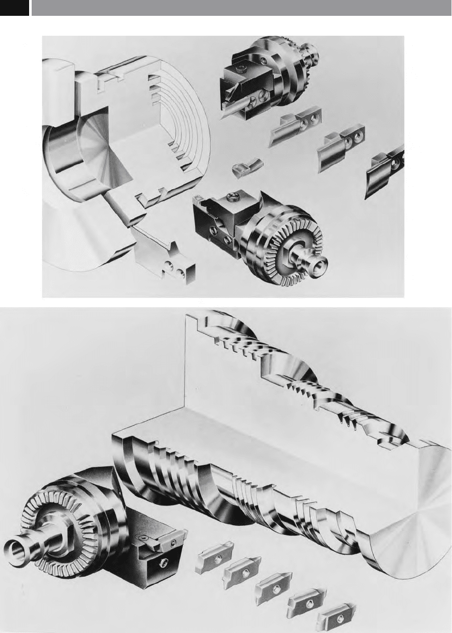
Figure 119. The ‘modular tooling concept’ based upon attachment of ‘front’- and ‘back-ends’ by the Hirth coupling, illustrating
both axial and transversal grooving of component features in this instance. [Courtesy of Widia Valenite]
.
222 Chapter 6

•
Axial tolerance – ± 0.0025 mm,
•
Radial tolerance – ± 0.0025 mm,
•
Cutting-edge height – ± 0.025 mm.
On say, a turning centre using this KM modular quick-
change tooling – for the ‘intermediate’ size range, the
‘front-and back-ends’
6
, can withstand tangential cut-
ting loads of 12 kN. At this level of cutting force, the
actual mechanically-clamped front-and back-ends
c
losely approximates to that of a ‘solid’ 32 mm square-
shanked toolholder – in terms of its mechanical integ-
rity. However, when the initial KM tooling review was
made concerning the ‘dimensional envelope’ of ma-
chines that might employ this modular quick-change
s
ystem, it was found that a 40 mm round-shanked sys-
tem was the largest that could be easily accommodated
(i.e. see Fig. 122). Hence, this diameter was selected
for the coupling, with adaptors for sizes ranging from
2
5 to 80 mm, for use on both turning and machining
centres.
Once the basic conguration had been established
and selected, to meet both the dimensional and re-
peatability criteria, the actual shape of the mechani-
cal coupling could be considered. It was evident that
the male portion of the mechanical coupling would
be used for the cutting tool unit, as it would present
the smallest overhang, therefore being less inuenced
by deections resulting from high tangential loading
whilst roughing cuts were taken. A secondary, but
nonetheless important operational factor, was that a
male cutting unit would provide more protection for
the taper and the locking mechanism, once the cutting
unit was removed.
With the taper’s geometric conguration yet to be -
nally determined – more will be mentioned on this sub-
ject in the next paragraph, it was necessary to decide on
the method of achieving contact between the taper and
t
he face. From a design viewpoint, there are two basic
methods of providing this face contact, these are:
1. Metal-to metal contact – by holding very close tol-
erances on both halves of the mating male and fe-
male couplings,
2. Elastic distortion at contact – by designing a small
amount of elastic distortion into the coupling as-
sembly.
6 ‘Front-and back-ends’ , is general workshop terminology that
refers to the cutting unit (i.e front-end) and its mating tool-
holder situated in either the pocket, of tool post (i.e. back-
end).
As the male portion of the mechanical interface was
located and attached to the cutting tool, any such de-
formation would take the form of expansion of the fe-
male taper in the clamping unit. In exhaustive testing
procedures, an optimum performance occurred with
a combination of pull-back force coupled to elastic
deformation. is latter method of utilising an elas-
tic distortion design, resulted in improved static and
dynamic stiness, when compared to the much more
costly manufacturing technique of metal-to-metal
conguration of the alternative mechanical coupling.
When the design and geometry of the taper size
was considered, it was determined that the gauge-
line
7
diameter had to be as large as possible, in order
to promote the highest possible stiness to the tool-
ing assembly. As the wall thickness would have been
a
ected a compromise of 30 mm was decided upon.
e nal design decisions concerning the joint-cou-
pling were concerned with its length and taper angle.
For example, if a steep taper angle had been utilised,
this greater angle would have caused an increase in the
force required to produce the necessary elastic defor-
mation in the female half of the coupling. Conversely,
a slow taper – of smaller included angle, would have
had the eect of increasing the force necessary to sep-
arate the male and female tapers – acting like a ‘self-
holding taper’. erefore, aer this design evaluation
exercise, the latter ‘self-holding’ version was selected,
as it produced the optimal taper, namely of: 1 : 10 by
2
5 mm long. is taper angle and length gave the best
combination of stiness and forces for locking and
unlocking the mating parts. e taper equated to the
ubiquitous Morse taper and, had the added bonus that
limit gauges
8
were commonly available for checking
tolerances during their production.
Once the coupling geometry had been established,
the locking mechanism could be considered. Using
computer-aided design (CAD) techniques and in par-
ticular, sophisticated soware, namely, nite element
analysis (FEA), allowed for a full investigation of the
locking mechanism in-situ within the relevant por-
tions of the male and female tapers. Techniques such as
FEA, were utilised on key portions of the mechanical-
7 ‘Gauge-line’ , refers to the taper length and its respective
diameter. From here, is where the taper’s length is datumed,
for tool oset measurement of the cutting unit in the tool-pre-
setting machine, for ‘qualifying tooling’.
8 Limit gauges, are a form of attribute sampling of the Go and
Not Go tolerances for this Morse taper.
Modular Tooling and Tool Management 223
interface couplings, to ensure that the correct strength
and durability levels occurred. Moreover, extensive
‘life-testing’ was also conducted, to avoid unexpected
failures of the tools in-service, which might otherwise
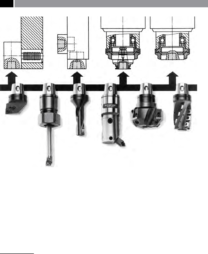
prove signicantly costly to remedy. e locking mech-
anism (i.e. indicated by the sectional line diagrams in
Fig. 120 – top) used hardened precision balls to pro-
duce a system which has high mechanical advantage
9
,
9 Mechanical advantage (MA), is the term used to obtain
greater output from a smaller input, using some mechani-
cal mechanism, such as by using either a: lever, pulley, disc-
springs, etc. A mechanism’s mechanical advantage, can be
expressed in the following manner:
MA = Load (N)/Eort (N) no units
For example, in this case the MA was 3.5: 1 for the ball-lock-
up sequence, using the 55° machined angle in the taper, giv-
ing: the resulting coupling a clamping force of >31 kN, this
being produced by either a draw-rod, or disk-spring pulling
force of 8.9 kN.
coupled to low frictional losses and was a reasonably
low-cost solution. is tooling mechanism employing
a
mechanical-interface for the ‘front- and back-end’ ,
produced a locking force of >31 kN, while tting into
the taper with a gauge-line of just 30 mm. e ball-
lock mechanism used two balls that locked into the
machined holes through the taper shank of the cut-
ting unit (Fig. 120 and 121). is lock-up congura-
tion, allows either a φ9 m
m draw-rod, or disk-springs
to be used to apply the necessary pull-back force. e
holes in the tapered shank – into which the balls are
seated, have a machined angle of 55°, this results in a
mechanical advantage of 3.5 : 1. As the disk-springs –
used in this method – are pulled back, it forces the two
balls radially outward until they lock into the tapered
machined holes, as depicted in Fig. 122 – where an Al-
len key T-bar is used to activate the lock-up sequence,
via a series of back-to-back disk-spring washers. To
release the cutting unit’s front-end, a force is applied
by the T-bar, which pushes these disk-springs and re-
leases the balls, while at the same time it ‘bumps’ the
Figure 120. The ‘modular tooling concept’ based upon both angular and face contact, illustrating a variety of rotating and
stationary holders and machining operations. [Courtesy of Widia Valenite]
.
224 Chapter 6
cutting head and in so doing, releases it from its self-
holding taper.
Referring to the lock-up sequence once more. Once
the cutting unit is inserted into the female taper (i.e.
back-end), it makes contact at a stand-o distance of
0
.25 mm from the face. erefore, as the locking force
is applied, a small amount of elastic deformation oc-
curs at the front of the female taper. As the cutting tool
is locked-up, there is a three-point contact that takes
place: at the face, the gauge-line and at the rear of the
taper. Finally, if one compares the coupling’s stiness
with that of a solid-piece unit which has been ma-
c
hined to identical dimensions, then when a 12 kN
is applied – to simulate tangential cutting loads – the
dierence in deection between them, would be only
5 µm. Hence, this modular coupling tooling assembly,
closes approximates to that of the ultimate rigidity
found if a solid-piece cutting tool was utilised.
Tooling Requirements for Machining Centres
Machining centres with their in-situ automatic load/
unload tool-changers and tool-storage carousels, or
magazines, have reduced cut-to-cut times signicantly,
allowing faster response times to the next machining
requirement of the CNC program. If a tooling-ap-
praisal is made of the tool-storage facility of machining
centres, it would soon be apparent that less-than-total
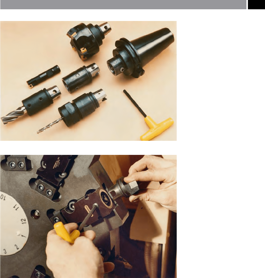
Figure 121. ‘Modular tooling con-
cepts’ allow ‘qualied tooling’ to be set
up with the minimum of adjustments,
thereby signicantly reducing down-
time. [Courtesy of Kennametal Hertel]
.
Figure 122. ‘KM’ modular quick-
change tooling system being manu-
ally-tted/changed – using the T-bar
wrench, into a turning centre’s turret.
[Courtesy of Kennametal Hertel]
.
Modular Tooling and Tool Management 225

capacity occurs. is noticeable under-storage tooling
capacity may be due to one, or more of the following
reasons:
•
Heavy tooling requirement in the tool-stor-
age system – because of the tool storage system’s
c
onguration – such as a chain-type magazine (Fig.
115) – tools have to be widely-spaced to allow the
magazine to be kept evenly-balanced,
•
Large tools situated in the magazine – this nor-
mally requires that the adjacent pockets must be
le empty, so avoiding them fouling each other
upon magazine rotation (Fig. 115),
•
‘Sister-tooling’ requirement – this allows for dupli-
cation of the most-commonly-used tools, as they
are more susceptible to breakage, or wear, enabling
longer overall machining time for the production
run, prior to a complete tool changeover.
NB
is latter point of employing a ‘sister tool’
strategy, has the eect of signicantly reducing the
variety of tools that can be held in the nite amount
of pocket-space available on many magazines, car-
ousels, etc.
In order to increase the capacity of a tool-storage
system, while simultaneously expanding the range
of tools that are available during a production run,
modular tooling has been developed which further
extends the machine’s capability and versatility. With
today’s modular tooling all being of a ‘qualied size’
10
,
they can be prepared from a centralised preparation/
storage facility, then transported to the machine tool
automatically – more will be said concerning this level
of sophisticated tool management toward the end of
the chapter.
So far, the relative merits of utilising a modular
quick-change tooling system for machining centres
has been discussed. Today, such systems can be used
for both rotary and stationary tooling operations on
m
achined workpieces. A ‘tooling exemplar’ , of such
10 ‘Qualied tooling’ , this refers to all of the tool’s osets be-
ing known – this allows the tool to be tted into its respective
pocket in the tool storage facility, with the tool oset table up-
dated, allowing the tools to be utilised, without the need for
presetting on the machine tool, prior to use.
NB Previously mentioned with regard to Boring operations
in: Chapter 3, footnote 41.
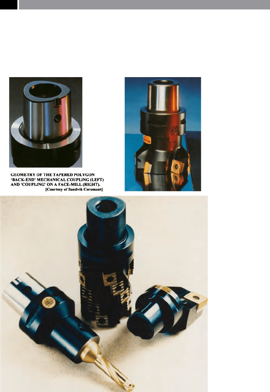
tools, is the ‘Capto system’
11
, being an amalgamation
of a self-holding taper and a three-lobed polygon (i.e.
see Figs. 123 to 125). is novel tooling mechanical in-
terface design, features a tapered polygon, which is an
extremely dicult geometric shape to manufacture for
both male and female couplings (Fig. 123-bottom le).
However, this tapered polygon oers multiple-point
contact in a robust and precision coupling, allowing
high torques to be absorbed for both rotating and sta-
tionary tooling (Fig. 124). Complete ‘Capto’ systems –
ranging in their available diameters – are presented for
a variety of machine tool congurations, which are ob-
tainable with a wide variety of ‘back-ends’ to suit many
diering tool pocket styles (i.e. see Fig. 125 – e.g. ISO,
VDI, ANSI, etc.).
In order to enhance the use of say, the ‘KM-type’
of modular tooling still further and to ensure that a
positive location between mating faces occurs, it is
possible to utilise an electronically-activated back-
pressure device, coupled to the CNC controller. With
this system in-situ, the tool-locking procedure, could
be as follows:
1. ‘
Old tool’ is removed from ‘front-end’ – this oc-
curs by either activation of the tool-changer (i.e. on
a machining centre), or a tool-transfer mechanism
(i.e. on a turning centre),
2. C
ompressed air purges the female taper – this has
the eect of cleaning-out the debris – nes
12
– from
the previous tool’s cutting operation,
3. ‘
New tool’ is inserted into ‘back-end’ of toolholder –
its male taper is cleaned, then it begins to seat itself
in the female taper,
4. A
s it is pushed rmly home to register with its op-
posing taper – the back-pressure is electronically
monitored and, a signal indicates that seating has
taken place and this data is sent to the CNC control-
ler, conrming coupling has been rmly locked,
11 ‘Capto system’ , was developed by a leading tooling company,
its name is derived from the Italian word for: ‘I hold rmly’
– which seems somewhat appropriate for an excellent me-
chanical interface between the ‘front- and back-ends’ on a
modular tooling system.
12 ‘Fines’ ,
are either minute particles resulting from the tool ‘re-
cutting eect’ – in the form of small slivers of material, or is
the result of dust/debris created when brittle-type material in
particular, has been machined and these particles may elec-
tro-statically attach themselves to the machined mechanical
interface coupling’s mating surfaces.
226 Chapter 6
5. Tool is ready for use – this unmanned operation al-
lows the next turning, or machining operation to
commence.
NB Q
uick-change tooling of this level of sophisti-
cation needs to be coupled to some form of tool-
transfer mechanism, in order to gain the full bene-
ts of its potential range of machining applications
and speed of operation, to minimise the pay-back
period.
e spindle nose taper tment is an important factor
in obtaining the necessary accuracy from modular
quick-change tooling (Fig. 126a). Here, the ‘spindle
cone’ must run true to the spindle’s Z-axis and the
pull-stud pressure should be checked to ensure that it
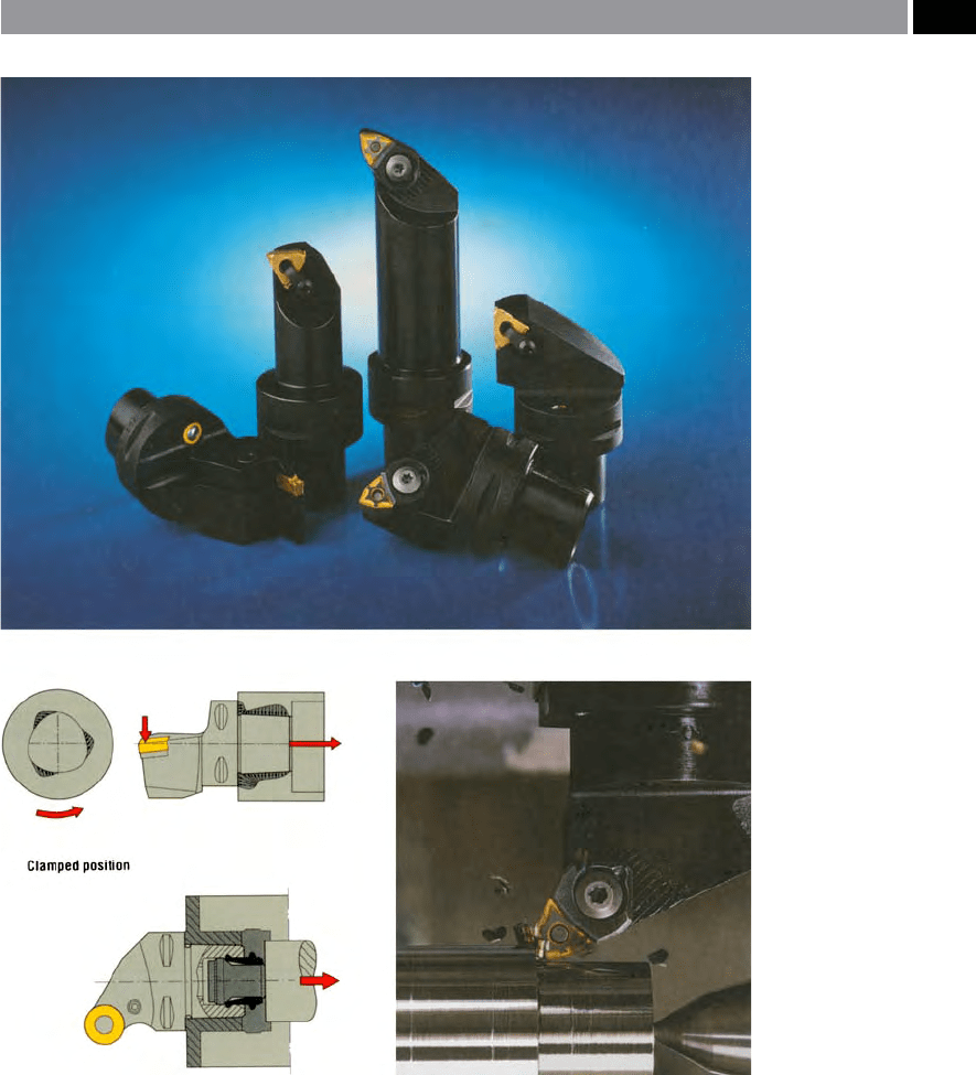
Figure 123. Modular tooling ‘capto’ with tool security and precision location via face and lobed
taper contact. [Courtesy of Seco Tools]
.
Modular Tooling and Tool Management 227
is within the machine tool manufacturer’s guidelines.
Oen when problems occur at the spindle taper, it is
the result of several factors:
•
Pull stud pressure variation – this should be
checked to ensure that it is within manufacturer’s
specication,
•
Spindle nose dri – this is the result of perhaps
running the spindle at continuously high rotational
speeds, resulting in the spindle nose cone ‘ther-
m
ally-growing’ , leading to the simultaneous: X-, Y-
and Z-axes driing several micrometres (e.g. this
t
hermal driing can oen account for around 10 µm
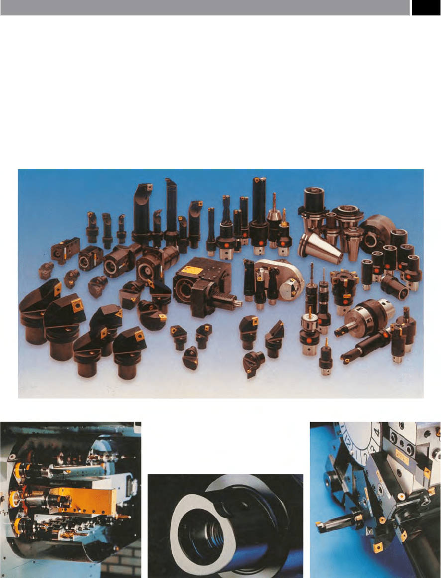
Figure 124. Modular
tooling (Capto) illustrating
stationary (turning) and
rotational tooling (milling,
drilling, etc.), with indenti-
cal lobed and tapered
‘back-ends’. [Courtesy of
Sandvik Coromant]
.
228 Chapter 6
of compound angular ‘spindle cone’ movement),
which could present a problem for any close toler-
ance component features requiring machining.
NB When these problems occur, the whole cut-
ting tool assembly, can become ‘unbalanced’ ,
this is particularly true for high cutter rotational
speeds.
Much more could be said concerning tool-changing
techniques, where tool transfer arms are discarded
in favour of the whole magazine, or tooling carousel
being moved to the spindle to speed-up tool-chang-
ing even further. Alternatively, gantry-type tool/
work delivery systems are available, or complete tur-
rets previously equipped with ‘qualied’ tooling can
be delivered, for un-manned operations, in a ‘lights-
Figure 125. The vast range of modular (capto) tooling available for:
• machining centres,
• turning centres and
• mill/turn centres.
[Courtesy of Sandvik Coromant]
.
Modular Tooling and Tool Management 229

out’
13
environment. e techniques for tool delivery
to keep machine tools in operation virtually continu-
ously is a vast topic, which goes way beyond the cur-
rent scope of this existing tooling-up discussion.
All of these rotational modular quick-change tools
can be successfully utilised up to speeds of approxi-
m
ately 12,000 rev min
–1
, without any undue problems.
However, once rotational tooling speeds increase
above this rotational level, then invariably it is neces-
sary to redesign the tool assemblies, allowing them to
be dynamically balanced, this will be the theme of the
next section.
6.4 Balanced Modular
Tooling – for High
Rotational Speeds
When rotational spindle speeds are very high, the con-
ventional ball-bearing spindles are limited and have
a
n upper velocity of ≤80 m sec
–1
, this is where the balls
lose contact with the journal walls and begin to pro-
mote ‘Brinelling’
14
within the raceways. It is not usu-
ally the case, for a conventional milling spindle to be
u
tilised at rotational speeds >20,000 rev min
–1
, without
due regard for the: centrifugal force, frictional eects
and spindle cone roundness levelling variations, that
are likely to be present beyond these speeds. For any
dynamic unbalance
15
of the tooling assembly to occur,
this will happen, if the mechanical interface is not se-
13 ‘Lights-out’ machining environments, refer to either com-
pletely un-manned machining, or minimal-manning levels.
Some companies, run an fully-automated machining ‘night-
shi’ without any personnel in attendance, allowing the lights
to be turned out, thereby saving signicant electrical power
cost, when this factor is taken over the year’s usage.
14 ‘Brinelling’ ,
creates break-down and delamination of the
raceways as the ‘unrestrained’ hardened balls strike both the
internal and external races at high speeds, causing them to
prematurely and catastrophically fail in-service.
* Brinell hardness – uses a ø10 mm steel ball – hence the
name.
15 ‘Dynamic unbalance’ ,
can occur in either of the two tooling
planes, these are either radial, or axial movement, related to
the high rotational speeds of the cutter assembly. In many
cases, dynamic dual-plane balance can be achieved, using spe-
cialised tool assembly balancing equipment (i.e. see the chap-
ter concerning high-speed milling applications).
cure – more will be said on this subject in the chapter
describing high-speed milling operations. With bal-
anced tooling in mind, cutting tool assemblies were
developed that minimised rotational unbalance, being
based upon the HSK taper tment, shown in Figs. 126b
and 127. e most important advantages of this ex-
emplary mechanical interface with its tapered hollow
s
hank, coupled to its axial-plane clamping mechanism
(i.e. based upon: HSK-DIN 69893), is as follows:
•
High static and dynamic rigidity – the axial and
radial forces generated in the tool shank, provide
the necessary clamping force,
•
High torque transmission and dened radial po-
sitioning – the ‘wedging eect’ between the hol-
low taper shank and holder/spindle, causes friction
contact over the full taper surface and the face (Figs.
127ci and cii). Two keys engage with the shank end
of the toolholder, providing a ‘form-closed radial
positioning’: thereby excluding any possibility of
setting errors,
•
High tool-changing accuracy and repeatability
– the circular form engagement of the clamping
claws within the hollow tool shank, provides an
extremely tight connection between the shank and
holder/spindle (Fig. 127cii),
•
High-speed machining performance – improves
in both locking/clamping power and eectiveness
with increased rotational speed. e direct initial
stress between the hollow shank and the spindle
holder, compensates for the generated spindle ex-
pansion promoted by centrifugal force and, in so
doing, negates any radial play. e face contact
clamping, prevents any slippage in the axial direc-
tion (Fig. 127cii),
•
Short tool changing times – due to much lighter
tooling, when compared to a conventional ISO
taper: the shank is about 1/3 of its length and, ap-
proximately 50% lighter in weight,
•
Insensitive to ingress of foreign matter – the un-
interrupted design of the ring-shaped axial plane
clamping mechanism, simplies coupling cleaning.
During an automatic tool-change, compressed air
purges mating surfaces and provides cleaning at the
interface,
•
Coolant through-feed – via centralised coolant feed
by means of a duct, which also excludes ingress of
coolant, as the front- and back-ends are entirely
sealed – preventing fouling of the mechanical inter-
face,
•
Tool shank construction is both simple and eco-
nomic to produce – as no moving parts are present,
230 Chapter 6
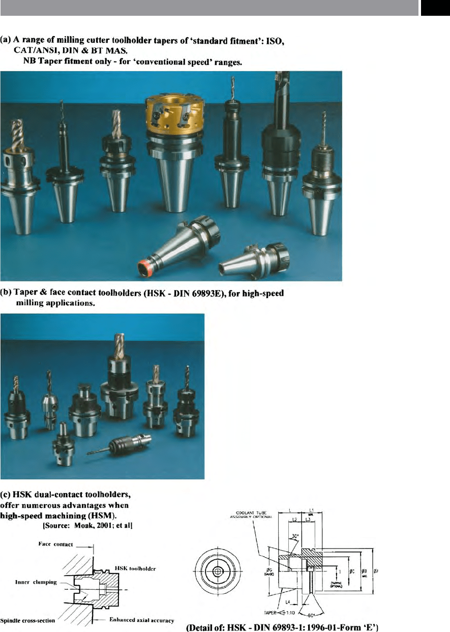
Figure 126. Milling cutter toolholder taper tment. [Courtesy of Sumitomo Electric Hardmetal Ltd.].
Modular Tooling and Tool Management 231