Smith G.T. Cutting Tool Technology: Industrial Handbook
Подождите немного. Документ загружается.


cic location within the company’s premises. A list is
then compiled, allocating every machine tool’s: power
capacity, spindle taper, number of spindles, its current
operating condition
25
, present tooling utilised, plus the
current and past operations performed on each ma-
chine tool. By organising information concerning the
capital equipment capability and availability, produces
a number of distinct benets, including a knowledge of
the machines basic characteristics, thus ensuring that
the most advantageous machine tool can be selected
and any machining operation is performed using the
optimum parameters.
Knowledge gained from such a study of perishable
and capital equipment, allows for improvements in
both: process planning – the action plan for the manu-
facturing of a certain part, together with production
planning – the best use of a factory’s resources for a
particular workload.
Building-Up the Tool File
Probably the principal users of a tool le within any
manufacturing organisation are the Process Engineer
and Part-programmer, with perhaps the Tool-preset-
ting operator and Stores-personnel, also making use
of this ‘le’. It should be stressed that new tools are
only added to the tool le aer a proper investigation
of the need for them, assuming that such tooling was
not previously listed. By accepting this limitation on
25 ‘Operating condition’ , this machine tool activity is invariably
of some concern, as although some form of periodic mainte-
nance is likely to be undertaken, perhaps less attention is given
to the machine’s current state of calibration. is situation can
be diagnostically-achieved, both speedily and eciently by
the use of telescoping ‘Ball-bars’. is calibration equipment
can undertake a quick ‘health-check’ and assess both the static
and dynamic machine tool’s performance, indicating the fol-
lowing important characteristics: Servo-mismatch, Stick-slip,
Reversal spikes, Scale uncertainty, Straightness, Squareness,
Lateral play, Back-lash, Cyclic error. ese machine tool re-
lated-factors are automatically prioritised by the soware,
then they can then be simply: analysed, diagnosed and then
corrected, together with a machine tool ‘health-check’ report.
NB Many companies perform these full diagnostic ‘health-
checks’ , periodically, or simply prior to a shi commencing,
as they can be undertaken in just a few minutes for a ‘quick
assessment’ , or perhaps a more thorough ‘Ballbar’ assess-
ment can be achieved in just a few hours – when a convenient
‘maintenance window’ occurs.
the number of dierent tools in the tooling inventory,
then a company can be assured that when the tools are
‘called-up for use’ in the manufacturing process they
will be available and backed-up with spares, since the
‘stores’ has access to this ‘le’. An important feature of
any tool le is the cutting data and machining times
listed. ese machining data are known to be achiev-
able and will be those values expected to be employed
during component production. More specically, the
data values are the ones utilised to calculate quotation
prices for the product, for any future customer ap-
praisal. e editor of the tool le has a key role to play
in the acquisition of tooling data, so when building up
t
he ‘le’ , they have to:
•
Scrutinise any reported deviations – from the re-
corded cutting data and the original tool le,
•
Investigate higher productivity ratings – some
newly-available tooling may lay claim to be both
faster and more ecient in comparison to either its
predecessor, or competitors tooling products,
•
Obsolete tooling should be ‘weeded-out’ – particu-
larly with the introduction and addition to the tool
le of newer high-technology tooling,
•
Investigation of new tooling – to see if claims of
new tooling products, with regard to their: geom-
etry, coatings, performance, etc., are a genuine im-
provement over the previous versions used.
e systematic accumulation of tooling knowledge in
the tool le for each section of the manufacturing
operation, ensures that the cutting performance will
‘
continuously improve’
26
. Such improvements may be
considered to be analogous to improving the skill of
an operator on a conventional machine tool, but with
more exibility, as the tool le system soware is able
to cope with much more diverse and complex tooling
26 Continuous improvement programs’ , were originally devel-
oped in Japan and are now well-known and are oen termed
‘Kaizen’ *, which is a philosophical and rigorous approach to
process/product improvements, based upon:
(i) Satisfying the customers – in order to keep the business
alive and to be more protable,
(ii) Being both customer- and process-oriented – to promote
vigorous improvements here,
(iii) Requiring commitment and participation of a company’s
personnel – using their knowledge and experience to achieve
continuous improvements in both working practices and in
the product’s quality.
*In Japanese, Kaizen, approximates to: ‘Change to the better’.
242 Chapter 6

situations. A ‘well-disciplined’ and ‘active’ tool le,
completely eliminates the anticipated ‘hiccups’ that are
likely to occur, whenever a new Part programmer is
employed, or even when hiring new Stores personnel,
or Machine operators, for that matter!
With the soware structure of the tool le – of
necessity – being highly complex and interrelated in
nature, it is not possible within the connes of this
chapter to go into too much detail showing how the
operating system works. However, an appreciation of
a simpler, but still valid tool le format can be gleaned
by describing how a ‘manual le’ is produced. Prior to
constructing this manual tooling data-base, a separate
record is produced for each tool, which is cross-refer-
enced to separate cards for cutting inserts that can be
utilised with the tool. In essence, there are four ‘elds
of tooling information’ that are needed for a usable tool
le, these are:
1. T
ooling is built-up from modular elements – which
are the ‘key’ to eective management and control,
as they allow the widest range of tooling for an ex-
tensive assortment of machine tools available, from
the minimum number of tooling elements in stock.
Hence, a tool for a given machining application may
be assembled from dierent modular elements, to
suit a range of machines,
2. Materials Requirement Planning (MRP)
27
– the
system together with the tool stores should support
the tooling from the tool le, with such items as:
spares, consumables, plus back-up tooling. In order
to achieve this objective, the tool le record would
include details of the build-up for each tool as well
as the stores location for each part, using a specic
‘key’ notation,
27 ‘Materials Requirement Planning’ (MRP*), is a soware-
driven system that enables manufacturing companies to
calculate: how many materials are needed, what particular
types that are required, plus at what times they are needed. To
achieve this level of control, the system utilises a sales order
book, which records known future orders and also a ‘fore-
cast’ of what sales orders the business is reasonably condent
it might have won. en, the MRP soware interrogates and
checks all the ‘components/ingredients’ which are required to
make these future orders and ensures that they are ordered in
time.
*MRP, was originally developed in the 1960’s and is some-
times termed MRPI, to dierentiate it from the ‘derived’ MP-
RII system – see Footnote 18.
3. Certain ‘steering comments’ on tooling – normally
these statements are based upon shop-oor expe-
rience, that are included to enable the Process-, or
Planning-engineer to select the appropriate tool for
the desired machining application,
4. O
rganisation of basic cutting data – this is nor-
mally produced so that the data can readily be in-
cluded into the CNC program.
NB
is cutting data is organised according to the
component to be machined and the optimum or-
ganisation of this machining data will vary from
one company to another, depending on their needs.
Of course, all of this data listed reects the compa-
ny’s actual experience, in particular, it includes the
results of any ‘optimisation exercises’ (i.e. Machin-
ability trials – more on this later) previously under-
taken in the machine shop.
Practicalities when Star ting-Up a Tool File
Whenever a tool le system is initiated, the important
point to observe is to: start small and keep the tooling
information to be included ‘sound’. Having accepted
this principle, a company may start to build-up the
tool le steadily – over perhaps a month, including
any practical test data for maybe a hundred, or so of
the most popular tools utilised. is information now
residing within the tool le, will ow through the tool-
management system and, it will begin to highlight
the requirements of the system users, driving forward
the le’s further development. Conversely, a company
may embark on a more comprehensive tool le sys-
tem, incorporating all the machining data available on
perhaps two thousand tools, but utilising provisional
cutting data, instead of well-proven information. With
this rather heavy-handed and rapidly-built tool le
approach, the probable outcome will mean that the
whole ‘le’ has incorporated many ‘dud tooling solu-
t
ions’ , thereby ensuring that the system is discredited,
even before it is correctly operating at anywhere near
its optimum level.
Obtaining meaningful test results and tool assess-
ments does not necessarily demand extra eort from
the company, merely the organisation of endeavour
already being made by the company’s ‘Tooling-engi-
neers’ and those from the tool suppliers. Oen, most
of the tooling trouble-shooting activities will dissipate
once the current component batch is completed, sim-
Modular Tooling and Tool Management 243

ply because there is no framework in which this vital
information can be recorded – for future usage. So,
all the time and pain’s-taking eort needed to collate
‘sound’ tooling data is disregarded and the informa-
tion is discarded. So, when then a repeat batch order
duly arrives, the whole tooling-related data-gather-
ing process must once again begin, by ‘re-inventing
the wheel’ – this being a total and unnecessary, but is
costly waste of everybody’s time!
Tool-kitting servicing to the machine shop must
be based upon the assurance that the completed kits
are dependable, whilst providing the maximum secu-
rity from a limited budget for tooling stock. Usually
there is a nite tool stock available, with the objec-
tive being to utilise, for example, the same modular
tools across a range of machine tools. For this reason,
modular quick-change tooling, has seen a widespread
acceptance by machining-based companies of late.
Yet another important factor in any tooling requisi-
tion for a specic machining operation, is the inherent
quality of the tools used. One of the major function’s
of the tool-kitting area, is to monitor and control the
quality of delivery of tooling within the manufactur-
ing environment, by accessing the ‘tool data ow’ for
both out-going ‘new kits’ and in-coming tooling ‘old
kits’ from completed production runs. As batch sizes
become smaller, the ‘logistical-ow’ of kits speeds-up.
e eectiveness of the tool-kitting personnel will be
inversely-proportional to the number of tooling items
on the inventory and the ‘standard’ they must control.
is problem of eective tool control, is a further ar-
gument in favour of a factory-wide standardisation of
the tooling inventory. erefore, in summing up tool-
ing-related activities within the production location,
two main factors emerge, these are:
1. L
inking every tool with its application technology
– this is normally achieved in such a manner that it
is the most productive tools that are chosen for new
jobs and not the old ones – just because they have
been previously used and are known to be sup-
ported by the tool stores. is tool selection strat-
egy, will result in the optimum cutting conditions
being selected,
2. F
ormulating a rationalised and optimised tool
management ‘standard’ – this is essential as it sup-
ports tooling across the breadth of the whole fac-
tory.
NB W
hen purchasing any new tooling, or machine
tools, reference to this ‘standard’ is of the essence
for the overall system to operate eectively.
6.5.3 Overall Benefits of a Tool
Management System
By the correct implementation of a basic, but compe-
tent tool management control system, the following
list highlights the ‘rewards’ that can be expected:
•
Manpower is conserved and training requirement
minimised,
•
e number of tools lost, or misplaced is reduced,
•
Timely and up-to-date information on tool usage is
produced,
•
Tool inventory shortages are identied and pre-
vented,
•
e accuracy of the tooling inventory is improved,
•
Inventory levels and excess purchasing are mini-
mised,
•
Time spent on re-ordering, etc., plus ‘piecemeal
purchasing’ are reduced,
•
Record-keeping functions are consolidated,
•
Tool tracking and tooling availability within the
machine shop is monitored,
•
Tools in rework can be tracked,
•
A record of scrapped tools can be kept,
•
Obsolete tooling can be identied and then elimi-
nated,
•
e cost of the total tooling inventory can be criti-
cally-assessed,
•
e gauges and xtures supplied with the tool kits
can be identied and tracked,
•
Machine tool set-up, tool-return and withdrawal
times are reduced,
•
Possibility of pin-pointing over-use machining
problems, by specic personnel,
•
Improper charge-outs, losses, or pilferage can be
minimised,
•
Space requirements and overheads are reduced,
•
Possibility of incorporating existing tool numbers
and current mode of operation into an automated
system, without making radical changes.
Tool management systems provide all of the above
benets, by allowing the operations to be easily re-
ported, analysed and corrected, enabling timely de-
cisions to be made, concerning the tooling, with the
minimum of manpower and operational changes
n
ecessary. So that the information required by a com-
pany can be obtained, the system should be organised
to allow personnel responsible for the tools to record
t
heir activities. On the ‘shop oor’ , it is the usual prac-
tice to allow two basic groups of the workforce levels
of responsibility/access to the system to provide both
244 Chapter 6

vital and helpful tooling information, these are the:
Tooling-supervisor and Stores personnel.
So far, the information on Tool management sys-
tems has been principally concerned with the justi-
cation and benets that accrue through the adoption
by a company and the philosophy underpinning its
practical application. In the ‘continuous circle’ of tool
monitoring and control, the tool-kitting area is at the
‘heart’ of the overall tool management procedure. is
vital day-to-day activity of tool preparation and set-
ting, will be the subject of the following section.
6.5.4 Tool Presetting Equipment
and Techniques
for Measuring Tools
Introduction
Cutting tools that are to be utilised on CNC machine
tools for the production of workpiece features, need to
have exact measurement information regarding their
osets known, so that the CNC program can automati-
cally displace (i.e. oset) the tool these dimensional
distances, in order to perform the intended machining
task. Otherwise, major errors in the machined com-
ponent’s dimensional features would result. Hence,
cutting tooling can be classied under three distinct
headings, these are:
1. Unqualied tools – these are tools that do not have
known dimensions, therefore they must be inde-
pendently measured and these values can then be
located and placed into a ‘suitable eld’ within the
CNC Controller’s tool table. Typical of such tooling,
are special-purpose form tools that may be consid-
ered to full this classication,
2. Semi-qualied tools – these are tools where not all
of the tool measurement oset data are known. For
example, a typical Jobber drill’s diameter would be
normally be known – say, φ1
2 mm
28
, but perhaps its
length for the purposes of utilising it immediately
would not. erefore, it would necessitate measur-
28 Whenever a tool’s dimensional size is known, it is necessary to
refer-back to the individual tooling manufacturer’s tolerance
specication, in order to establish the limiting values when
this data is utilised, when the tool is to be used without any
form of pre-measurement being undertaken.
ing the drill’s length, once it has been suitably lo-
cated and held in an appropriate chuck,
3. Qualied tools – are when all the tool oset data
are known and this information can be readily in-
put into the CNC controller’s tool table. Typically,
‘Modular quick-change tooling’
29
, can be consid-
ered under this category.
Presetting on the Machine Tool – Tool Contacting
When setting an ‘unqualied’ tooling dimension –
such as a drill’s length, on the machine tool, this being
the crudest form of tool presetting*. It is achieved on
say, on a vertical machining centre, in the following
manner: the cutting tool’s tip is held in the machine’s
spindle and is positioned over the table, being slowly
‘
jogged-down’
30
until its just touches a suitable ‘setting
29 Modular quick-change tooling, such as the ‘front-end’ cutting
units, tted into the already machine tool-pocketed and lo-
cated ‘back-ends’ , typied by the ‘KM tooling’ ranges (i.e. see
Figs. 120 to 122), would give the following repeatability read-
ings:
• Axial tolerance ±0.0025 mm,
• Radial tolerance: ±0.0025 mm,
• Cutting-edge height tolerance: ±0.025 mm.
NB All of these tooling manufacturer’s tolerances, limit the
machining tolerances that can be held, unless they (i.e. already
placed within quick-change tools in their respective holders)
themselves are measured, which tends to negate the rationale
for their original purchase!
30
‘Jogging-down’
– sometimes referred to as ‘inching-down’ , is
a manual means of slowly lowering the tool’s tip down onto a
surface – in this case a known height ‘setting-block’. is lin-
early-controlled action is achieved, by employing the ‘hand-
wheel’ , which allows the handwheels angular rotation to be
equated to an operator preselected incremental amount. is
incremental motion can be changed to a smaller value, as the
block is slowly approached, to give a sense of ‘feel’ (i.e some-
what like using a ‘feeler-gauge’), as contact is made between
the tool and the block.
NB e tooling is usually kept stationary while this manual
setting activity is undertaken.
* is is not strictly the most basic tool setting method, as the
‘cut and measure’ technique – then setting this measured value
in the tool table, is the most primitive and time-consuming
procedure of tool oset setting.
Modular Tooling and Tool Management 245

block’
31
. e Z-axis position is then noted and its value
is automatically entered into the tool table, giving a
‘semi-qualied’ tool oset, that can then be used for
the important Z-axis motion – when coming down
onto the workpiece’s surface to begin engaging in the
rst cut. If each tool length has to be input into the tool
t
able’s ‘osets’ , then this simple procedure has several
disadvantages: it is labour-intensive, ties-up cycle con-
siderable time, it is rather inaccurate and, it sets only
one oset dimension. In the case of turning centres,
the technique of determining osets is dierent, but
similar limitations still apply.
A tool presetting device is oen used on many of
today’s machine tools, this technique is typied by the
ubiquitous ‘
touch-trigger probe’
32
. Hence, this type of
tool-contacting presetting probe fulls a number of
‘
quoted benets’ , such as:
•
Setting/re-setting of tool length and diameter (Fig.
133b) – automatically up-dating, or correction of
the respective tool table osets, even while the tool
is still rotating,
•
Measurement of a complete tool station – automat-
ically in just a few minutes,
31 ‘Setting blocks’ , are usually manufactured from hardened steel,
that have been accurately and precisely ground to a known di-
mensional size and tolerance, nominally to some conveniently
‘round gure’ , for example:100 mm in height. ese ‘blocks’
are usually either rectangular, or round in cross-section. e
rectangular ones are preferred, because dierent nominal di-
mensions can be utilised for each adjacently at and square
face. e tolerance for the ‘Setting block’ should be ‘very close’ ,
as any dierence from the nominal size when input into the
tool table, will impinge on the overall workpiece tolerance, in
essence, somewhat reducing the tolerance’s ‘working range’.
32 ‘T
ouch-trigger probes’ **, in the simplest form these ‘tool
probes’ are omni-directional switches, that are sprung-loaded,
which when the tool makes contact with either an attached
setting cube, or a cylindrical ‘setting gauge’ (Fig. 133b), it im-
mediately breaks the electrical circuit. is loss of electrical
contact occurs when the three equi-spaced precision rods:
each one seated on two precision balls (i.e. each rod being po-
sitioned at 120° to each other) in a simple kinematic seating
mechanism, are lied/pushed either individually, or ‘as one’
out of their respective seating(s), which triggers an ‘electrical
pulse’ representing a nominal dimension and is automatically
recorded as either a length, or radius – in the case of a rotating
tool, which then automatically up-dates the tool table’s osets
for this tool.
**On a turning centre (Fig. 133a), this tool setting touch-trig-
ger probe, is termed a ‘tool eye’.
NB A small vertical machining centre with a 12 to
15 tool station, would take at least 5 minutes per
tool, with the traditional manual technique, men-
tioned above (i.e. see Fig. 133-bottom right, inset
graph/description).
•
Elimination of manual setting errors – tools that
are set manually, particularly tooling such as a large
diameter face mill, it will be open to errors when
setting both height and diameter osets. is is
because each cutting insert may ‘stand proud’ in
its respective seating, giving a false oset reading
– when stationary. Ideally, the whole tooling assem-
bly needs to be rotated as its oset is set,
•
No presetting of tools is necessary – as this is auto-
matically undertaken on the machine tool,
•
Accurate and precise ‘First-o machining’
33
– this
is the result of condence in the tool osets, set by
t
he ‘probing system’ ,
•
In-cycle tool breakage detection – at convenient
and programmed pre-selected intervals, the tool’s
osets can be checked for either: tool wear – to a
prescribed level, or tool breakage, which will auto-
matically stop the machine preventing either fur-
ther workpiece damage, or part-scrappage,
•
Improved condence in unmanned machining
– due to the fact that tool breakage detection pe-
riodically occurs, untended machining operations
can be undertaken.
ese are ‘real benets’ that occur when using ‘on-ma-
chine’ tool presetting equipment, but the ‘down-side’ of
such systems is they do utilise some potential in-cycle
cutting time. is negative eect using some of the cy-
cle-time, can be signicantly reduced for the following
presetting system, employing non-contact laser-based
tool setting techniques.
33 ‘First-o machining’ , this term is self-explanatory, in that it
is the rst component produced in a batch which is simply
known as the ‘First-o’ the machine. Invariably, this initial
component produced, is subject to rigorous inspection proce-
dures, being the ‘initiator’ for calculated data concerning the
whole batch’s metrological and statistical variability/consis-
tency.
246 Chapter 6

Figure 133. Cutting tool osets being set on a turning and machining centre. [Courtesy of Renishaw plc].
Modular Tooling and Tool Management 247

Presetting on the Machine Tool –
Non-Contacting Tool Setting
In recent years, laser systems for tool setting and bro-
ken tool detection on CNC machining centres have
become popular (Fig. 134), as manufacturers realise
the benets of fast process set-ups and in-process
feed-back on the tool’s current condition, particularly
on diminutive tooling that cannot be easily measured
by the more usual contact-type sensors.
Laser non-contact tool setting systems, utilise a
beam of laser light which passes between a transmit-
ter and a receiver, located either on the bed of the
machine, or on each side of it allowing the beam to
pass through the ‘working volume’ (Figs. 134a and b).
Hence, the tool’s passage through this beam, causes a
reduction in light as seen by the receiver, which will
then generate a ‘trigger-signal’. is ‘triggered-signal’
for the machine’s actual position, is instantly recorded
and from which, the tool’s dimensional characteristic
can be derived. Not only can the system measure the
required tool’s dimensional parameters, it can also be
used to detect broken tools. is tool breakage process
involves rapidly moving the tool into a position where
it can intersect the laser beam, so, if the light reaches
the receiver, then the tool’s tip, or point, must be either
missing, or broken. ere are quite considerable ben-
ets that accrue by the application of a non-contact
laser tool setting system, these include:
•
Rapid measurement of both tool length and di-
ameter – tools can be moved into the laser beam
at high speed, without risk, or any attendant dam-
age and the tool osets are automatically up-dated
(Fig. 134a),
•
Fast tool setting times can be achieved – tools can
be measured at normal rotational speeds, allowing
tooling assembly and taper tment errors such as
radial run-out, taper ‘pull-back’ to be identied,
then compensated for by the system,
•
Minute, or delicate cutting tools can be conve-
niently measured – without any subsequent tool
wear, or damage (Fig. 134b),
•
Tool breakage can be checked at very high
feedrates – this ecient process minimises cycle-
time, while increasing condence in untended ma-
chining applications,
•
Multi-point tooling can have each facet checked –
this is automatically undertaken while the tool ro-
tates,
•
Monitoring tool settings on the machine – enables
compensation for any ‘t
hermal movement’
34
of the
machine spindle.
Although the measurement process lasts for only a few
seconds, this is long enough for the chance of a falling
coolant drip to intersect the laser beam, possibly creat-
i
ng and attendant measurement error. Hence, the laser
tool setting equipment, must be able to distinguish
between reductions in light at the receiver, created by
a ‘falling object’ (i.e. termed: ‘drip-rejection’) as com-
pared to rotating tool, if it is to avoid ‘false-triggering’
producing tool measurement errors. is elimination
o
f ‘false-triggers’ , is achieved by the ltering-out of
signals by the electronic interface, this value being set
at a pre-determined ‘trigger-threshold’. It should be
noted, that the laser tool setting system cannot cope
with following circumstances: the presence of ‘ood-
c
oolant’ , cutter edge and prole checking, nor with
radial broken tool rejection processes.
e cutting edge laser measurement is quite a
complex process, when the tooling assembly is both
rotating and in linear motion simultaneously. If one
considers the relative motion of just one of these cut-
ter’s teeth, then, its edge moves in a circular path and
superimposed onto which will be the axial feedrate,
this motion being perpendicular to the laser beam.
Hence, for each of the tool’s revolutions, the promi-
nent edge approaches the laser beam by an increment,
this value is the feed per revolution. Such incremental
movement, introduces a potential error into measure-
ment of the tool’s size. For instance, if a tool rotates
a
t 1,000 rev min
–1
while feeding toward the laser beam
at 100 mm min
–1
, it will be seen to advance by 100 µm
between intersections of its prominent cutting edge
34 ‘ermal movement’ of the machine spindle, is important, as
the whole tooling assembly can eectively ‘grow’* due to ther-
mal eects, which may present problems – if not compensated
for – when very tight machining tolerances have to be held, or
maintained across either a high-quality machined component,
or for consistency in a large batch run.
*Tests undertaken, on a vertical machining centre equipped
with a ball bearing spindle – utilising a special-purpose ‘Invar’
spindle analyser – with the tooling being rotated at 3,000 rev
min
–1
under ‘no-load conditions’ for one hour, have produced
the following thermal results: Z-axis dri 9.2 µm, Y-axis dri
6.3 µm and X-axis dri 0.7 µm. Additionally, the bearing itself,
had some radial error motion present – as indicated in a ‘po-
lar-plot’ , this value being typically: 4.6 µm for the total radial
error.
248 Chapter 6
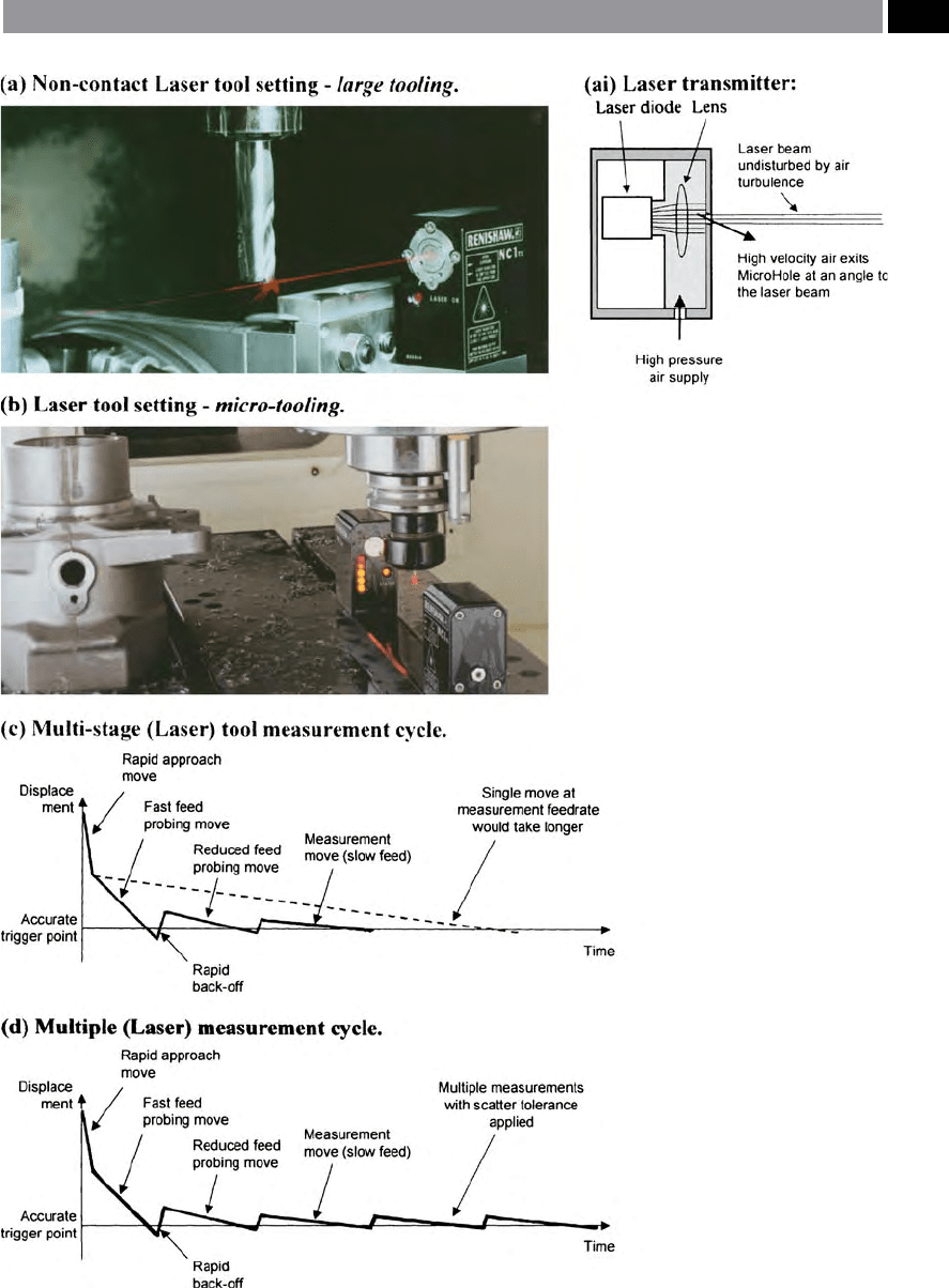
Figure 134. Automatic cutting tool setting and tool breakage detection, utilising an ‘on-machine’ non-contact laser.
[Courtesy of Renishaw plc]
.
Modular Tooling and Tool Management 249

to that of the ‘stationary position’ of the laser beam
– this being the maximum possible ‘feed per revolu-
tion’ error for any one particular reading. Conversely,
an improved accuracy can be obtained by rotating the
cutter faster, but advancing more slowly. For example,
i
f one wants only a 1 µm rev
–1
intersections, this level
of accuracy can be obtained by rotating the tooling at
3
,000 rev min
–1
,while advancing at only 3 mm min
–1
.
In order to minimise cycle times, the tool measure-
ment soware, programs the machine tool to move the
tooling into the beam initially from a ‘stand-o dis-
tance’ that is adequate to account for the uncertainty of
tool assembly build-up – this is important when setting
the tool’s length, if the tool is held in a collet, or simi-
larly-designed toolholder. So, the initial move is a fast
feedrate to gain an approximate position with respect
to the laser’s beam, from which the tool is backed-o
by a small linear distance. Here, the tool is ‘probed’ at
a reduced reduced feedrate, this is necessary to more
accurately nd the tool’s location, from where a very
short distance ‘back-o’ move is executed. Finally, a
m
easurement move is completed at a very low feed-
rate, so that an accurate measurement is tenable. is
complete tool checking process is considerable quicker
than approaching with the laser beam at a constant,
but low feedrate, from a larger ‘stand-o distance’ – see
Fig. 134c. While, yet another challenge to precise and
accurate tool measurement, is the result of the pres-
ence of either coolant, or debris on the tool’s tip which
is about to be measured. e most signicant prob-
lem facing non-contact sensing, when compared to its
equivalent contacting techniques – this latter method
achieves ‘hard-contact’ with the tool and can thereby
safely ignore any coolant lms, or liquid drips – is that
in the former case no actual tool contact occurs. is
lack of contact in the presence of uid media, can be
overcome by rotating the cutting tool assembly at very
high speeds, so as to dislodge any uid residue, or per-
haps another strategy is by utilising an air-blast on the
tool for non-contact measurement.
Yet another soware technique that can be used, is
the capacity to measure the tooling several times and
apply a ‘scatter tolerance’ to check for any variation
r
esulting from measuring ‘something’ , other than the
tool itself (Fig 134d). is soware routine will retake
readings until it obtains several values within the re-
qu
ired tolerance – these ‘tool-checking retries’ , plus
the ‘scatter tolerance bandwidth’ can be pre-selected
by the user.
e detection of broken tools is somewhat less de-
manding than for tool measurement – in terms of ac-
curacy and precision, although the cycle-time tends to
be more critical. e demands on a laser broken tool
detection system require it to be ‘active’ at the instant it
is required and, be able to operate under the prevailing
conditions, instantaneously aer machining stops. e
laser transmitter for the non-contact tool detection
system shown in Fig. 134ai, has been designed with a
‘MicroHole™’
35
, this ensures that the presence of cool-
ant does not aect the integrity of the laser system. In
practice, the laser system reliably operates under rela-
tively ‘harsh’ workshop conditions and the broken tool
detection system works in the following sequential
manner:
1
. Tool’s end is moved at rapid traverse into the laser
beam by 0.2 mm,
2. Tool breakage cycle is activated via an M-code from
the CNC controller,
3
. End of tool dwells in the laser beam for between 0.1
to 0.3 seconds,
4
. If laser light is received by the optical receiver unit for
more than a specied time-period, typically 10 µs,
then this distinguishes a broken tool is present,
5
. If laser light is not received by the optical receiver
unit, then the tool’s condition is satisfactory,
6
. Tool is the moved rapidly to its respective home po-
sition – end of cycle.
NB
is detection cycle also enables small tools to
be inspected, even when in the presence of ‘ood-
c
oolant’ , thereby minimising cycle-times.
ese laser non-contact tool setting systems, oer
many more soware-based features, not described
here, such as: cutter prole checking routines, together
with many inspection/checking routines for either tool
measurement, or broken tool detection. Furthermore,
laser tool setting systems provide machining-based
companies with a rapid, exible, accurate and precise
approach to control tooling dimensions and oer the
techniques necessary to increase machining automa-
tion.
35 ‘MicroHole™’ – both for the laser transmitter and the opti-
cal receiver, incorporate an angled aperture of just 0.75 mm
diameter, as this ensures that protection from: coolant, chips,
swarf and other debris such as machined graphite nes oc-
curs, because of a continuous stream of air that ows through
and along the laser beam – protecting it as schematically il-
lustrated in Fig. 134ai.
250 Chapter 6
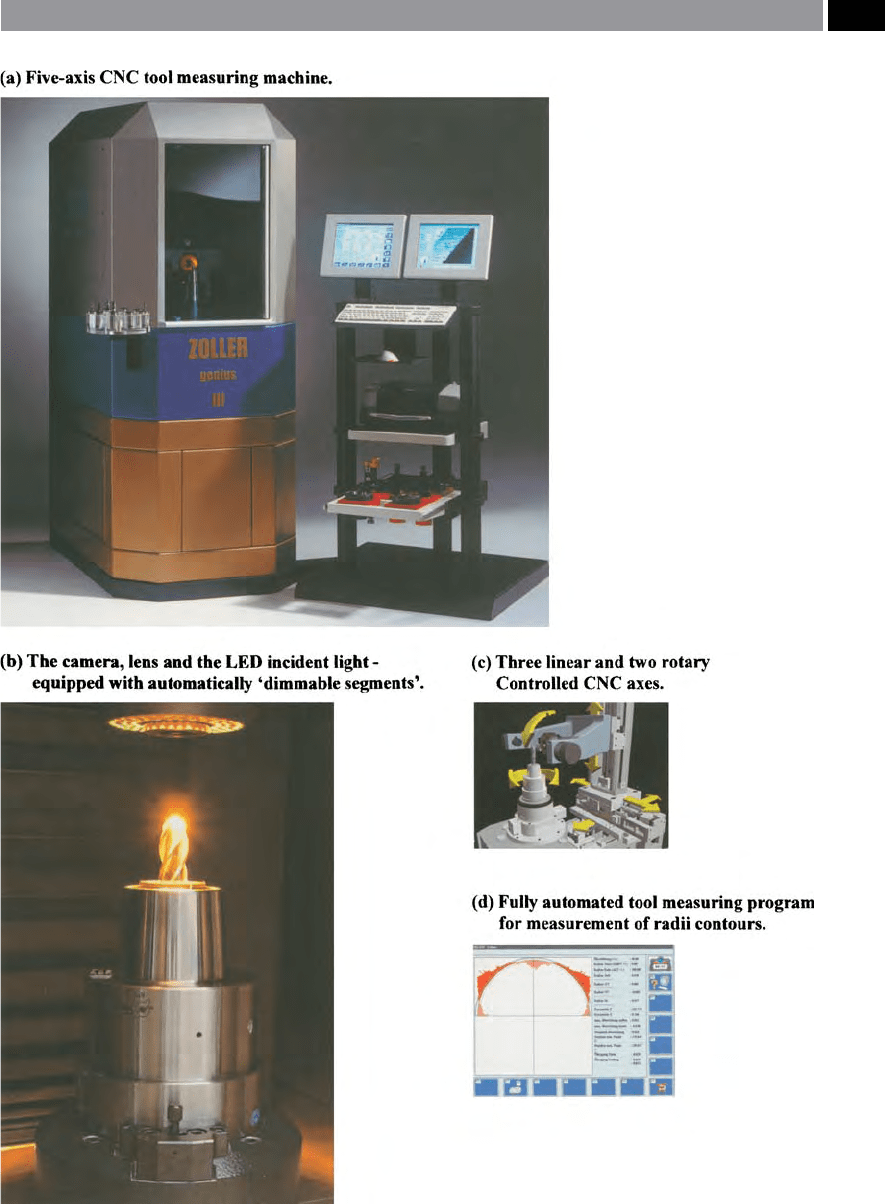
Figure 135. An automated ve axis CNC universal tool measuring machine for metrological and geometric inspec-
tion. [Courtesy of E. Zoller GmbH & Co. KG]
.
Modular Tooling and Tool Management 251