Shani G. Radiation Dosimetry: Instrumentation and Methods
Подождите немного. Документ загружается.

70 Radiation Dosimetry: Instrumentation and Methods
Equation (2.185) gives in units of MeV/g if
is
given in g/cm
3
. To obtain in Gy, one needs to multiply
by the factor , where e is the
elementary charge.
The dose delivered right after the protons have lost
the energy may be written as .
The dose at the actual depth z is then obtained by
folding the Gaussian depth straggling into by means of:
(2.187)
The calculation of , i.e., the consideration of
straggling for the fraction of protons that have nuclear
interactions, is less straightforward but also less critical,
because these protons contribute a smaller and smoother
amount to the total dose.
One can write as the convo-
lution integral [53]
(2.188)
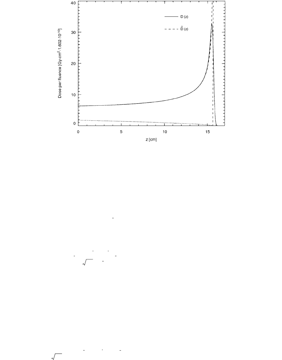
The resulting Bragg curves with and without consid-
eration of straggling are shown in Figure 2.54.
An attempt to include density heterogeneity effects in
the analytical dose calculation models for proton-treatment
planning using a dynamic beam delivery system was made
by Schaffner et al. [54] Different specialized analytical dose
calculations have been developed which attempt to model
the effects of density heterogeneities in the patient’s body
on the dose. Their accuracy has been evaluated by a com-
parison with Monte Carlo calculated dose distributions in
the case of a simple geometrical density interface parallel
to the beam and typical anatomical situations. A specialized
ray-casting model which takes range dilution effects (broad-
ening of the spectrum of proton ranges) into account has
been found to produce results of good accuracy.
The dose calculation of Schaffner et al. consists of a
superposition of individual scanned pencil beams. The
description of the physical pencil beam uses calculated
look-up tables of the depth-dose curve and the depth-width
relation of a proton beam in water. The depth-dose curve
is characterized by the nominal beam energy and the width
of the initial energy spectrum (momentum band). The dose
deposited by a single proton of known initial energy is
derived from the Bethe-Bloch equation.
The formula for the dose deposited at a position (
x, y,
z) by a pencil beam along the z-axis and positioned at
is given by
(2.189)
FIGURE 2.54 Bragg curves with and without consideration of straggling for 150-MeV protons in water. The dotted line at the
bottom is the dose contribution from the fraction of protons that have nuclear interactions, i.e., or (these are
indistinguishable within the resolution of the figure). (From Reference [53]. With permission.)
D
2
z() D
ˆ
2
z()
D
ˆ
D
ˆ
10
9
eC 1.602 10
10
E
0
E
D
ˆ
1
zEE
0
,()()
D
1
z()
D
ˆ
1
D
1
z() D
ˆ
1
〈〉z() D
ˆ
1
z()
e
zz()
2
2
z
2
z()
2
z
z()
--------------------------------
zd
0
R
0
D
2
z()
Dz() D
1
z() D
2
z()
Dz() D
ˆ
〈〉z()
1
2
---------------
D
ˆ
z()e
zz()
2
2
2
zd
R
0
x
0
y
0
,()
Dxyz,,()N
p
ID wer()
1
2
x
y
-------------------
x
0
x()
2
2
x
2
[]y
0
y()
2
2
y
2
[]expexp
Ch-02.fm Page 70 Friday, November 10, 2000 10:53 AM
Theoretical Aspects of Radiation Dosimetry 71
where
ID is the integral dose, interpolated from the depth-
dose look-up table; is the number of protons in
the beam spot; wer is the total water-equivalent range
(range shifter plates plus patient) along the central axis of
the beam; and are the standard deviations of the
Gauasians in
x and y directions. They include all contri-
butions to the beam width, i.e., initial phase space, Coulomb
scattering in the patient and range shifter and its propagation
in the air gap between range shifter and patient.
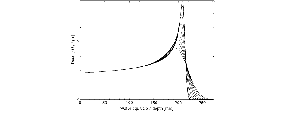
The resulting depth-dose curves for a relative range
dilution from 0 to 9% standard deviation are shown in
Figure 2.55. The influence of range dilution on the shape
of the Bragg curve is very high in the peak region, while
there are almost no changes in the plateau. This underlines
the importance of the peak region and justifies their
approach of calculating the range dilution only for protons
stopping in the point of interest.
Utilization of air-filled ionization chambers with
60
Co-
based reference calibrations in proton dosimetry requires
application of water to air stopping power ratios and the
mean energy required to produce an ion pair (W or w).
Proton dosimetry protocols recommend the use of calorim-
etry as the absorbed dose standard. Siebers et al. [55] used
calorimetry in conjunction with an ionization chamber
with
60
Co reference calibrations to deduce the proton w
value in the entrance region of a 250-MeV proton beam:
34.2 0.5 eV.
For high-energy charged particles (protons), the dif-
ferential value w is used since only a small fraction of the
particle energy is deposited in the ion chamber gas cavity.
For photon and electron beams, the stopping power ratios
and
W values are known to within a few tenths of 1%.
The dose delivered to the water calorimeter was deter-
mined from [55]:
(2.190)
with being the absorbed dose to water, c the spe-
cific heat of water, T the change in water temperature
measured using the thermistors, and the thermal defect
of water. Water temperature changes were monitored using
a Wheatstone bridge circuit. is expressed in terms of
the Wheatstone bridge deflection and the thermistor
calibration factor as
(2.191)
To evaluate ionization dosimetry, measurements were
made in a geometry similar to that used for the calorimeter
measurements through use of the dummy calorimeter. In
place of the thermistors, a Farmer-type PTW ionization
chamber (model W30001, volume 0.6 cm
3
, PMMA walls,
aluminum central electrode) was inserted into a water-
proof PMMA cap which was securely mounted in the core
region. Ionization charge measurements were made for
runs of length equal to that of the water calorimeter runs.
The ionization chamber calibration factor in the pro-
ton beam was determined from the calorimeter and ion
chamber responses by applying the recommendations of
the AAPM and ECHED code of practice.
(2.192)
FIGURE 2.55 Depth-dose curve for a 177-MeV beam with a momentum band of 1.1% and with a relative range dilution of 0–9%
in steps of 1%. (From Reference [54]. With permission.)
wer wer x
0
y
0
z,,()
t
i
wer x
0
y
0
z,,()()with ixy.,
N
p
x
y
,
D
c water,
cT 1 D
T
()
D
c water,
D
T
T
V
u
T V
u
N
D
P
D
c water,
MP
ion
CIS, att()
p
----------------------------------------
Ch-02.fm Page 71 Friday, November 10, 2000 10:53 AM

72 Radiation Dosimetry: Instrumentation and Methods
where is the proton calibration factor, is the
dose measured using the calorimeter [Equation (2.190)],
and M is the charge collected in the ionization chamber,
corrected to reference temperature and pressure condi-
tions. corrects for recombination in the ionization
chamber and corrects for inverse square and
attenuation (depth-dose) variations due to minor geomet-
ric differences between the calorimeter and the dummy
calorimeter. The proton calibration factor for an ionization
chamber with a
60
Co reference calibration is
(2.193)
To determine , the calorimeter-based calibration
factor [Equation (2.192)] is set equal to the calibration
factor determined from the
60
Co-based calibration.
is solved to reveal
(2.194)
In Equation (2.194), the subscript air refers to dry air,
whereas gas denotes humid air. The equivalence
can be made by assuming that
humidity corrections to w values are independent of irra-
diation modality.
X. CAVITY THEORY
Cavity theory is used to relate the radiation dose deposited
in the cavity (the sensitive volume of the detector) to that
in the surrounding medium. The dose to the cavity
depends on the size, atomic composition, and density of
the cavity and the surrounding medium. The size of the
cavity is defined relative to the range of the electrons set
in motion. A cavity is considered small when the range
of the electrons entering the cavity is much greater than
the cavity dimensions. The electron spectrum within a
small cavity is solely determined by the medium surround-
ing the cavity. The ratio of absorbed dose in the cavity to
that in the surrounding medium is given by the Bragg-
Gray or Spencer-Attix theory. When the cavity dimensions
are many times larger than the range of the most energetic
electrons, the electron spectrum within the cavity is deter-
mined by the cavity material. A cavity whose dimensions
are comparable to the range of electrons entering the cav-
ity has a spectrum within the cavity that is partially deter-
mined by the medium and partially determined by the
cavity material. Burlin proposed a general cavity theory
to include all cavity sizes
A detector will give a signal proportional to the absorbed
dose in the sensitive detector material, which in general
differs from the medium. One can write
(2.195)
where is the dose to the radiation-sensitive material,
is the dose to the medium, and
f is the ratio of the
two doses. In case of photon radiation, the factor f can be
given either by the mass stopping power ratio , if
the detector is small compared to the electron range
(Bragg-Gray cavity), or by the ratio of the mass energy
absorption coefficients , if the detector is
large compared to the electron range. For both categories
Burlin’s theory yielded expressions combining both
and .
According to Bragg-Gray theory, Equation 2.195
becomes
where
is the mass stopping power ratio, is the charge
collected per unit mass of air, and
W/e is the energy
required to create one ion pair in air. When the incident
photon energy decreases, the energy absorbed in air in the
chamber increases and will finally invalidate the Bragg-
Gray condition.
The validity of the Bragg-Gray cavity theory in photon
radiation dosimetry for photon energies from 10 keV to
10 MeV has been investigated by Ma and Nahum [56]
quantitatively. The ratio of the absorbed dose result-
ing from photon interactions in an air cavity to that
in air under the condition of charged-particle equilibrium
has been used as a parameter to determine if the air
cavity can be classified as a Bragg-Gray cavity. Burlin
general cavity theory seriously overestimates the depar-
ture from Bragg-Gray behavior. For clinical photon
beams, the dose ratio is 0.29 for a 150-kVp beam and
0.27 for a 240-kVp beam, compared to 0.006 for a
60
Co-
beam, if the cavity is placed at a depth of 5 cm in water.
The study confirms that typical air-filled ionization cham-
bers cannot be considered to be Bragg-Gray cavities for
low- and medium-energy photon radiation.
For a given absorbed dose to the medium, , the
absorbed dose to the sensitive detector material in the case
of a small detector, , is in general different from that
for a large detector, . By substituting and
into Equation (2.195), in turn, one obtains
(2.196)
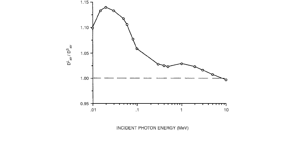
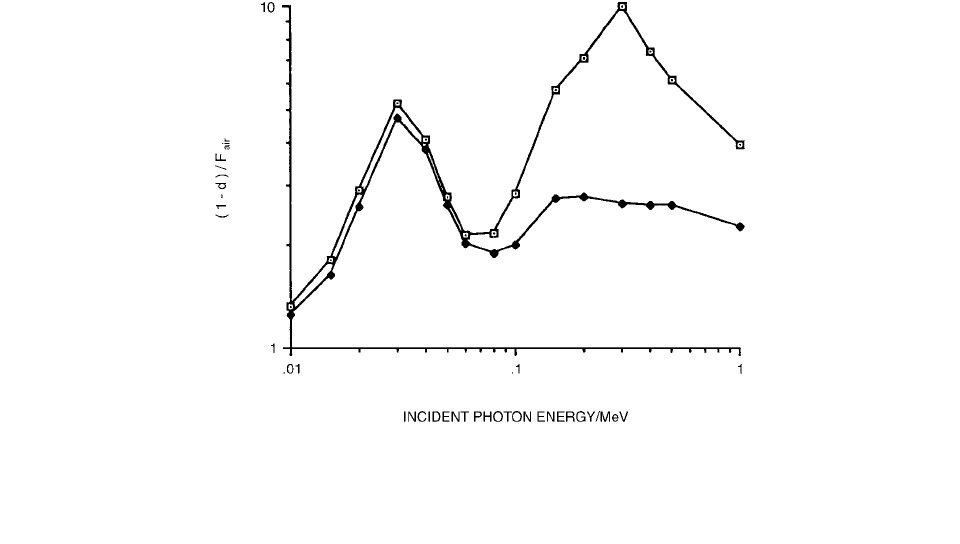
Figure 2.56 shows how the dose ratio, , cal-
culated using Equation (2.196), varies with energy when
a monoenergetic photon beam is incident on water and
N
D
p
D
c water,
P
ion
CIS, att()
p
N
D
P
N
gas
w
p
W
()
gas
S
,()
gas
water
p
p
w
p
w
p
W
()
gas
w
p
W
()
gas
w
p
W
()
air
D
c water,
MN
gas
S
,()
gas
water
p
p
P
ion
C IS att,()
p
---------------------------------------------------------------------------------
w
p
W
()
gas
w
p
W
()
air
D
med
fD
det
D
det
D
med
s
med,det
en
()
med,det
s
med,det
en
()
med,det
D
med
D
air
s
med,air
D
air
J
g
We()
s
med,air
J
g
F
air
D
air
PA
D
air
CP
E
F
air
D
med
D
det
S
D
det
L
s
med,det
en
()
med,det
D
det
L
D
det
S
s
med,det
en
()
det,med
D
det
L
D
det
S
Ch-02.fm Page 72 Friday, November 10, 2000 10:53 AM
Theoretical Aspects of Radiation Dosimetry 73
the (air-filled) detector is placed at a depth of 8 cm in
water (chosen to be greater than the maximum possible
CSDA electron range at all energies). The value of is
usually smaller than that of and the difference between
increases as the incident photon energy
decreases. This means that significant dosimetric errors
could be introduced by using such detectors at lower pho-
ton energies.
Suppose that an air cavity (i.e., without walls) is
placed at a depth in water where charged-particle equilib-
rium (CPE) has been established. The mean absorbed dose
in the air cavity, , can be divided into two parts; i.e.,
(2.197)
where is the dose resulting from the electrons gener-
ated by photon interactions in the surrounding water and
is the dose resulting from photon interactions in the
air cavity. If and the disturbance by the detec-
tor of the electron fluence present in the undisturbed water
is negligible, then the absorbed dose in the air cavity
depends solely upon the electron fluence present at the
depth of interest in water (the condition for Bragg-Gray
theory to apply). If is close to , the absorbed dose
in air under the CPE condition, then the absorbed dose in
the air cavity depends mainly upon the photon fluence
present at the depth of interest in water (the condition for
large detectors). For the intermediate case, if one still uses
the Bragg-Gray cavity theory, errors will occur, the severity
of which can be judged from Figure 2.56.
Let the quantity be a measure of
the validity of the Bragg-Gray cavity theory at different
photon beam energies; the condition for the Bragg-Gray
cavity theory to apply is . For a monoenergetic
photon beam of energy E, we have
(2.198)
where
is the photon fluence and is the mass
energy absorption coefficient of air at energy E. The dose
ratio, , for a monoenergetic photon beam of energy E
can then be expressed as
(2.199)
Suppose that one has a photon spectrum and wishes
to calculate the corresponding quantity, , for the
spectrum. This can be done by integrating over
the photon spectrum according to [56]
where is the photon fluence, differential in energy,
and ( is the mass energy absorption coeffi-
cient for air at energy
E.
The Burlin general cavity relation can be written as
(2.200)
FIGURE 2.56 The variation with the incident photon energy of the dose ratio, at a depth of 8 cm in water calculated
using Equation 2.196. The mass energy absorption coefficient ratios and the mass stopping power ratios were calculated using Monte
Carlo techniques. (From Reference [56]. With permission.)
D
air
L
D
air
S
D
air
S
D
ai
r
L
D
air
S
D
air
L
,
D
air
D
air
D
air
EW
D
air
PA
D
air
EW
D
air
PA
D
air
PA
D
air
D
air
PA
D
air
CPE
F
air
D
air
PA
D
air
CP
E
F
air
0→
D
air
CPE
E
en
()
air
en
()
air
F
air
E
air
E() D
air
PA
E
E
en
()
air
F
air
spec
F
air
E()
F
air
spec
F
air
E()
E
E
en
E()
()
air
Ed
0
E
max
E
E
(
en
E()
)
air
Ed
0
E
max
E
en
E()
)
air
D
det
ds
det med,
1 d()
en
()
det med,
[]D
med
Ch-02.fm Page 73 Friday, November 10, 2000 10:53 AM
74 Radiation Dosimetry: Instrumentation and Methods
where d is a parameter related to the cavity size that
approaches unity for small cavities and zero for large ones.
Burlin expresses (1 d) as
(2.201)
where L is equal to four times the cavity volume, V, divided
by its surface area, with
satisfying
(2.202)
That is, the maximum depth of electron penetration, T, is
to be arbitrarily taken as the depth to which only 1% of
the electrons can travel.
Suppose the CPE condition has been established and
the values of and are known. Then
one can write
(2.203)
By combining Equation (2.203) with equation (2.197),
one obtains [56]
(2.204)
By comparing Equations (2.200) and (2.204) and not-
ing that , Ma and Nahum arrived at
(2.205)
(2.206)
It is worth noting that, since is in general differ-
ent from either or , it is evident that [56]
(2.207)
This is ignored in the Burlin theory.
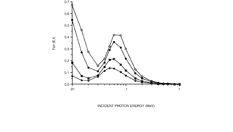
Figure 2.57 shows the ratio of the absorbed
dose in an air cavity of thickness
t and 6-mm diameter in
vacuum to that in air under the condition of CPE for
monoenergetic photon beams. Above about 0.1 MeV, the
dose ratio decreases rapidly with the incident
photon energy and becomes negligible for high photon
energies (smaller than 0.01 for photon energies above
500 keV). The curves exhibit maxima between
50 and 80 keV [ (80 keV, 6 mm) 0.41, (60 keV,
3 mm) 0.37, (60 keV, 1 mm) 0.22, and
(50 keV, 0.5 mm) 0.14]. The fraction of the photon
energy transferred to Compton electrons decreases
steadily with decreasing photon energy, whereas, for pho-
toelectrons, this fraction is essentially unity. As a conse-
quence of more secondary electrons resulting from
Compton interactions than from photoelectric interac-
tions, the total average energy transfer actually decreases
for photon energies greater than 20 keV, increasing again
only for photon energies greater than 60 keV.
Comparing values with the (1 d) values in Burlin
theory, we note the following. In Figure 2.58, the values of
(l d) normalized to are presented as a function
of photon energy for monoenergetic photon beams. The
Monte Carlo calculated results of the dose ratio, ,
show a much smaller fraction of the absorbed dose in the
FIGURE 2.57 The variation with the incident photon energy, E, of for an air cavity of thickness t and 6-mm diameter
in vacuum irradiated by monoenergetic photon beams. The Monte Carlo calculational uncertainty is smaller than 0.5%.
, t
0.5 mm; , t 1 mm; , t 3 mm; , t 6 mm. (From Reference [56]. With permission.)
F
air
Et,()
1 d()
Le
L
1()
L
e
L
0.01
s
det med,
en
()
det med,
D
med
s
med det,
D
det
S
en
()
med det,
D
det
L
D
air
D
med
D
air
EW
D
air
S
()S
air med,
D
air
PA
D
air
L
()
en
()
air med,
D
air
L
D
air
CP
E
F
air
D
air
PA
D
air
CPE
1 d
D
air
EW
D
air
S
d
D
air
D
air
S
D
air
L
D
air
EW
D
air
S
()D
air
PA
D
air
L
()1
F
air
Et,()
F
air
Et,()
F
air
Et,()
F
air
F
air
F
air
F
air
F
air
F
air
E()
F
air
E(
)
Ch-02.fm Page 74 Friday, November 10, 2000 10:53 AM
Theoretical Aspects of Radiation Dosimetry 75
air cavity resulting from the direct photon interactions
with the air in the cavity compared to that predicted by
Burlin theory. Using 0.04 instead of 0.01 in Equation
(2.202) only slightly reduces the difference between
and (l d).
The Burlin theory ignores all secondary-electron scat-
tering effects which results in large discrepancies in dose
to the cavity compared with the experimental results in
high atomic number media. Kearsley [57] proposed a new
general cavity theory which includes secondary-electron
scattering at the cavity boundary. The Kearsley theory
showed excellent agreement with experimental results for
60
Co
-rays but poor correlation for 10-MV x-rays. The
Kearsley theory has numerous parameters and the magni-
tude of the input parameters is arbitrary; therefore, the
dose to the cavity depends on the choice of parameters.
Haider et al. [58] have developed a new cavity theory which
includes secondary-electron backscattering from the
medium into the cavity. The strength of this proposed theory
is that it contains few parameters and a methodical way of
determining the magnitude of the parameters experimen-
tally. The theory gives better agreement with experimental
results in lithium fluoride thermoluminescence dosimeters
for
60
Co
-rays and 10-MV x-rays in aluminum, copper,
and lead than do the Burlin and Kearsley cavity theories.
Haider et al. assume that the Compton interaction is
the dominant radiation interaction and, thus, the applicable
energy range of the theory is from 500-kV to 20-MV x-
rays. The electron density is proportional to the energy
loss cross section of electron stopping power which is
mainly determined by the excitation energy of the mole-
cules and the Compton scatter cross section. When the
Compton process is dominant and the difference of mean
excitation energies per electron is small, then the stopping
power ratio averaged over the cavity volume is equal to
the ratio of electron densities, independent of cavity size.
The total electron fluence in the cavity of
thickness
t is divided into three groups: [58]
1. the electron fluence that originated in the cavity,
including the backscattered electrons generated
by it in the cavity traveling in the opposite direc-
tion ;
2. the electron fluence that originated in the
front-wall medium, including the backscat-
tered electrons generated by it in the cavity
traveling in the opposite direction ;
and
3. the electron fluence in the cavity resulting from
the difference in the backscattering coefficients
of the cavity medium and the back-wall medi-
um .
In the following, w is referred to as the front-wall medi-
um, g as the cavity medium, m as the back-wall medium,
and b as the backscattering coefficient. The electron flu-
ence in the cavity is given by
(2.208)
FIGURE 2.58 Values of the ratio (1 d)/ for an air cavity of 6-mm thickness and 6-mm diameter in vacuum; (l d) was
calculated using Equation (2.201) with
L 4 mm. For Burlin’s (l d),
was calculated using Equation (2.202) with T 0.95
. For Janssens et al.’s [73] (1
d), a constant of 0.04 was used in place of 0.01 in Equation (2.202). , Burlin; , Janssens
et al. (From Reference [56]. With permission.)
F
air
E()
R
SCDA
F
air
E()
egT,,
z()()
eg,
z()()
ew,
z()(
)
emb,,
z()()
egT,,
z()
eg,
z()
ew,
z()
emb,,
z()
Ch-02.fm Page 75 Friday, November 10, 2000 10:53 AM
76 Radiation Dosimetry: Instrumentation and Methods
Therefore, the dose to the cavity is given by
(2.209)
where is the mean mass collision stopping power. In
the absence of the cavity, the dose to the wall is given by
(2.210)
where the subscript c denotes the equilibrium fluence in
the wall medium (i.e., under charged particle equilibrium
(CPE), where dose is equal to the collision part of the
kinetic energy released in medium A (kerma). The ratio f
of the average dose to the cavity (g) and to the front wall
medium (w) is given by
(2.211)
where is the ratio of the mean mass collision
stopping powers of medium
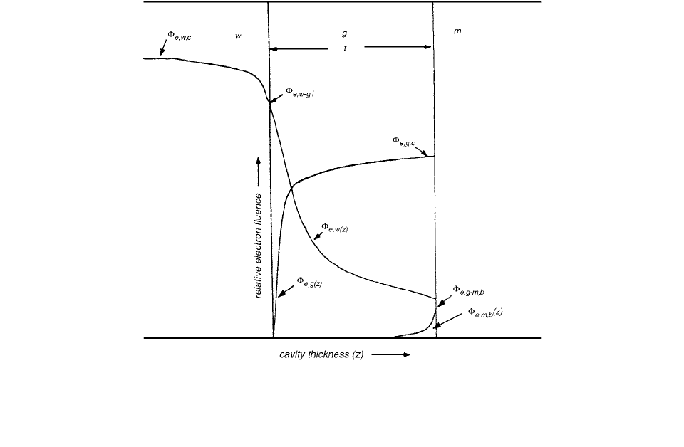
g and of medium w. ,
, and are functions of the distance z from the
front cavity interface (Figure 2.59). Each term can be
represented by the product of a distance-independent elec-
tron fluence term at the interface and a distance-dependent
weighting factor. Therefore, [58]
(2.212)
where is the equilibrium cavity fluence, is
the electron fluence at the front wall-cavity (w-g) inter-
face, is the electron fluence at the back wall-
cavity (g m) interface, and , and are dependent
weighting factors: is the ratio of the electron fluence
generated in the cavity medium at a distance z from the
front wall-cavity interface and the equilibrium fluence in
the cavity medium; is the ratio of the electron fluence
generated in the front wall medium at a distance z from
the wall-cavity interface (Figure 2.59) and the electron
fluence at the front wall-cavity interface; and is
the ratio of the backscattered electron fluence at a distance
(t z) from the back wall-cavity interface to the back-
scattered electron fluence at the cavity-back wall interface.
If the cavity and the wall materials are irradiated by
the same photon fluence separately, then the dose ratio
between the cavity and the wall under CPE is related by
the ratio of the average mass energy absorption coeffi-
cients. Therefore,
(2.213)
FIGURE 2.59 Illustration of cavity parameter. is the electron fluence that originated in the cavity (g), including its
backscatter. is the electron fluence spectrum that originated in the front-wall medium (
w) and its backscatter as it crosses
the cavity. is the electron fluence spectrum in the cavity resulting from the difference in the backscattering coefficient of
the cavity (
g) and the back-wall medium (m). (From Reference [58]. With permission.)
eg,
z()
ew,
z()
emb,,
z()
D
g
egT,,
z()S
〈〉
g
eg,
z()
ew,
z()
emT,,
z()()S
〈〉
g
S
〈〉
D
w
ewc,,
z()S
〈〉
w
fz()
eg,
z()
ew,
z()
emb,,
z()
ewc,,
--------------------------------------------------------------------------
S
〈〉
w
g
S
〈〉
w
g
e
g
,
ew,
emb,,
fz()
C
1
z()
ewc,,
C
1
z()
ewgi,,
C
3
z()
egmb,,
ewg,
----------------------------------------------------------------------------------------------------------------
S
〈〉
w
g
egc,,
ew-gi,,
e, gm, b
C
1
C
2
, C
3
C
1
C
2
C
3
D
g
D
w
-------
en
〈〉
w
g
Ch-02.fm Page 76 Friday, November 10, 2000 10:53 AM
Theoretical Aspects of Radiation Dosimetry 77
where is the mean mass energy absorption coef-
ficient. The dose ratio between the cavity and the wall is
also related by
(2.214)
using the relationship of Equation 2.210:
(2.215)
Let
F be the fraction of the total number of electrons
per unit area which crosses a reference plane r from left
to right in a medium under CPE and let b be the fractional
number of incident electrons that are backscattered from
the reference plane r traveling from right to left. In a
homogeneous medium, the total number of electrons or
the equilibrium fluence which includes the backscat-
tered electrons traveling in the opposite direction is given
by
(2.216)
The term is the total number of electrons per unit
area which crosses a reference plane r from left to right
and the team is the total number of backscattered
electrons crossing the same reference plane from right to
left. If the medium to the left of the reference plane r is
w and to the right of the reference plane is g, then the
electron fluence at the interface of w g is
given by [58]
(2.217)
where is the fractional forward electron fluence orig-
inating in the medium w and b
g
is the probability of back-
scattering of the medium g. If medium g of thickness t is
sandwiched between medium w and medium m, then the
relative backscattered electron fluence between medium g
and medium m at the interface g m ( ) is given by
(2.218)
where is the fractional forward electron fluence
of the total electron fluence arriving at the inter-
face
g m; is the backscattering coefficient of the
medium m; and is the difference in the backscat-
tering coefficient of medium g and medium m. Electron
backscattering within the medium g is already accounted
for in , and . consists of and ,
evaluated at cavity thickness t given by
(2.219)
where is the fractional forward electron fluence orig-
inating in the cavity medium and is the fractional
forward electron fluence originating in the front-wall
medium. and can be expressed by a prod-
uct of cavity size–independent electron fluence terms and
cavity size–dependent weighting factors. Therefore,
(2.220)
where and are the fractions of the electron fluences
and , respectively, that arrive at the interlace
g m of cavity thickness t.
When the cavity size is very large compared with the
range of the electrons, the above equations lead to the ratio
of the mass-energy absorption coefficients of cavity and
medium as in the Burlin and the Kearsley cavity theories.
When the cavity size is very small compared with the
range of the electrons and the front-wall and back-wall
mediums are identical, f reduces to the Bragg-Gray theory.
However, when the front and the back walls are not iden-
tical, f does not reduce to the Bragg-Gray theory. Since
the contributions from the front-wall, cavity, and back-
wall mediums are calculated separately, all three media
could be of different atomic composition. [58]
The weighting factors and are given by
(2.221)
where is the effective electron absorption coefficient
(cm
2
g
1
) in the cavity. [58]
XI. ELEMENTS OF MICRODOSIMETRY
Radiation dose in conventional dosimetry is a macroscopic
concept. Target volumes are many orders of magnitude
greater than the individual cellular entities which make up
tissue. The dose to a macroscopic multicellular volume is
obtained by the summation of the total energy deposited
by multiple radiation tracks over the volume divided by
the mass of that volume. Microdosimetry is the study of
radiation energy deposition within microscopic volumes,
where “microscopic” encompasses sensitive target volumes
ranging from the diameter of a cell (typically 20 mm) down
to the diameter of the DNA molecule (2
m). Although
microdosimetry is concerned with the same concept of
energy deposition per unit mass as dosimetry, the differ-
ence in size of the target volume of interest introduces
stochastic effects which are negligible in conventional
dosimetry. The magnitude and importance of stochastic
fluctuations in the target volumes depend greatly on the
target diameter, on the energy and linear energy transfer
(LET) of the particles, and on the relative number of
particles, i.e., the magnitude of the radition dose.
The fluctuations of energy deposition are incorporated
in the stochastic quantities of a subdiscipline of radiolog-
ical physics that has been termed microdosimetry. By
focusing on actual distributions of absorbed energy rather
en
〈〉
w
g
D
g
D
w
-------
en
〈〉
w
g
ewc,,
ewc,,
en
〈〉
w
g
S
〈〉
g
w
ec,
ec,
F
ec,
1 b()
F
ec,
Fb
ec,
e, wg,i
()
e, wg,i
F
w
ewc,,
1 b
g
()
F
w
e, wg,i
e, gm,b
F
e, gm,i
e, gm,i
b
m
b
g
()
F
e, gm, i
e, gm, i
b
m
b
m
b
g
eg,
ew,
e, gm, i
eg,
ew,
F
e, gm, i
e, gm, i
F
g
eg,
t() F
w
ew,
t()
F
g
F
w
eg,
t()
ew,
t()
F
e, gm, i
e, gm, i
d
4
F
g
egc,,
d
5
F
w
e, wg, I
d
4
d
5
egc,,
e, wg, I
d
4
d
5
d
4
1 d
5
()1
a
t()exp
a
Ch-02.fm Page 77 Friday, November 10, 2000 10:53 AM
78 Radiation Dosimetry: Instrumentation and Methods
than on their expected (mean) values, microdosimetry has
demonstrated the complexity of the problem of finding a
numerical index of radiation quality. On the other hand,
a realistic view of the pattern of energy absorption in
irradiated matter is essential for an understanding of the
mechanisms responsible for radiation effects, not only in
radiobiology but also in such fields as radiation chemistry
and solid-state dosimetry, and microdosimetry is required
in theoretical approaches to these subjects. Considerable
effort has therefore been expended in the measurement
and calculation of microdosimetric spectra. Once appro-
priate microdosimetric data were obtained, there were
efforts to employ them in radiobiology, radiation chemis-
try, and solid-state research. Such activities ran parallel
with further efforts in instrument design and an important
fundamental analysis of microdosimetry. [59]
The microdosimetric quantity that was first formulated
bears a relation to LET and it was, in fact, determined in
g scheme to derive t(L) by measurements of energy dep-
osition in a microscopic region termed the site. In a
spherical proportional counter made of tissue-equivalent
(TE) plastic, the energy that is deposited by an event (i.e.,
the passage of a charged particle) in a TE gas volume of
density
and diameter d is a good approximation to the
energy that would be deposited in unit density tissue
within a site of diameter d
. Since in the proportional
counters utilized,
is typically of the order of 10
5
, it is
possible to simulate very small tissue regions with
counters of convenient size. The quantity measured by
these devices was originally termed the “event size.” In a
later change, this became the lineal energy
y, which has
also been given a slightly different definition: [59]
(2.222)
where
is the energy deposited in an event and l is the
mean chord length in the tissue region simulated. (Origi-
nally the “event size’’ Y was defined as
/d, with d being
the diameter of the sphere. The newer definition of y
permits generalization to other shapes. In the case of the
sphere, l 2d/3.) This can be changed readily from a few
tenths to at least several tens of micrometers by a change
of gas pressure. Utilizing modern low-noise preamplifiers,
it is possible to measure most of the pulses corresponding
to a single ionization. (Because of the statistics of ava-
lanche formation in the proportional counter, initial ion-
izations result in a range of pulse heights). Pulse-height
analysis permits determination of the probability (density)
distribution f(y), i.e., the probability that the lineal energy
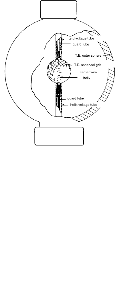
of an event is equal to y. A typical, widely used, TE-
counters design is illustrated in Figure 2.60. An example
for
60
Co y radiation is given in Figure 2.61.
The quantity termed the specific energy z (the original
name and symbol were “local energy density, Z”), which
applies to any number of events, is the stochastic analogue
of the absorbed dose and defined by
(2.223)
where
is the energy absorbed in a mass m in the receptor.
D, the average value of the absorbed dose in m, is equal
to , the average value of z.
The specific energy z that is produced by an event can
be expressed in terms of y because the mean chord length
in a convex body is 4V/S where V is the volume and S is
the surface. Accordingly,
(2.224)
where
is the density. For a unit density sphere,
(2.225)
when
z is expressed in gray, y in keV/
m, and d in
m.
Because of the statistical independence of events, a
y
l
FIGURE 2.60 Typical spherical proportional counter for micro-
dosimetry. The electrically grounded shell is molded from tissue-
equivalent (TE) plastic and the insulators are made of Lucite.
The spherical grid (TE) serves to largely eliminate the wall effect
that causes separate events in the simulated tissue regions to
coincide in the counter. The helix reduces variations of the electric
field along the center wire. These electrodes are of stainless steel.
The counter is traversed by TE gas at a pressure of the order of
10
3
Pa. The potential of the center wire is several hundred volts
positive and the potential of the helix is about 20% of this. The
spherical grid is at negative potential. An internal
or soft
x-ray source serves to calibrate the counter. (From Reference
[59]. With permission.)
z
m
z
z 4y S
()
z 0.204 yd
2
Ch-02.fm Page 78 Friday, November 10, 2000 10:53 AM
Theoretical Aspects of Radiation Dosimetry 79
knowledge of f(y) permits calculations of f(z,D), the prob-
ability (density) distribution for any value of the absorbed
dose D. This calculation involves , the frequency-averaged
specific energy in single events:
(2.226)
From this, one can obtain the mean number of events
n at dose D:
(2.227)
At sufficiently small values of D, there is usually no
event in a site and very rarely more than one. f(z, D) then
consists of a Dirac delta function
(z) and the single-event
distribution . This distribution has the same shape
as
f(y) and any reduction in D merely increases the relative
contribution of the delta function and reduces the fraction
of sites that receive an invariant spectrum of ener-
gies deposited in single events. At large values of D, when
, multiple events ultimately cause f(z, D) to assume
a bell-shaped curve about D. [59]
The product between the point-pair distance distribu-
tion and the measure of the site is termed the proximity
function of that domain. Thus, one has a proximity func-
tion of energy deposition
(2.228)
and a proximity function of the sensitive matrix
(2.229)
t(r)dr can also be defined as the expected energy imparted
to a shell of radius r and thickness dr centered at a ran-
domly chosen transfer point.
Proximity functions t(x) can be calculated from Monte
Carlo generated particle tracks. For monoenergetic parti-
cles (energy
T) one has
(2.230)
where
i and k refer to energy transfers, and , separated
by a distance between r and r r. The expectation value
refers to an ensemble of tracks. In simple cases t(r) can
be calculated directly. For a track segment with constant
LET, L (no radial extension of the track)
(2.231)
For a homogeneous distribution of energy transfers in
a medium of density exposed to dose D:
(2.232)
Equations (2.231) and (2.232) follow directly from the
definition of t(r). t(r) can not increase faster than for
any three-dimensional structure. The proximity function
can also be obtained directly from a series of microdosi-
metric measurements of in spherical sites of diam-
eter d: [59]
(2.233)
Microdosimetric concepts in radioimmunotherapy
were discussed by Humm et al. [60] There are three
principal areas where microdosimetry has been applied:
radiation protection; high LET radiotherapy, e.g., neu-
tron therapy; and incorporated radionuclides. In this lat-
ter category the importance of microdosimetry to the
radiobiology of radiolabeled antibodies is becoming
increasingly recognized. The objective of microdosime-
try is the complete characterization of energy deposition
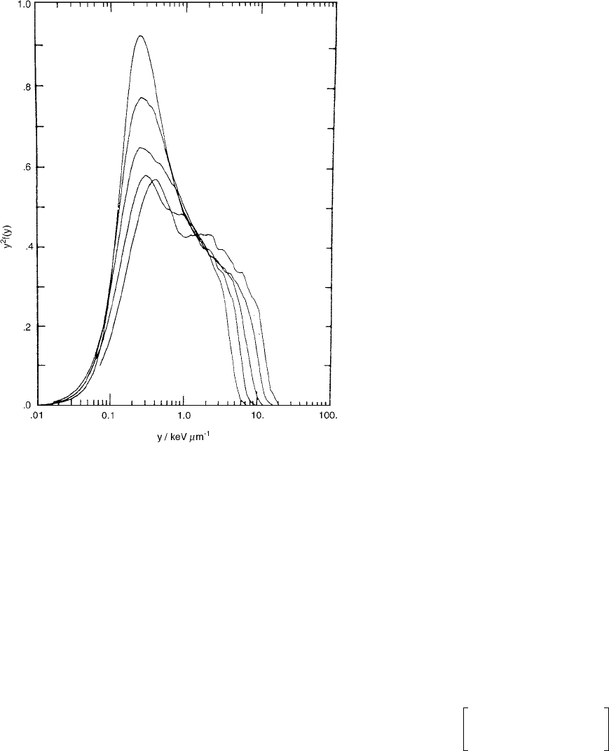
FIGURE 2.61 Microdosimetric spectra for
60
Co gamma radia-
tion. The spectra represent, from top to bottom, the following
site diameters: 8, 4, 2, 1, and 0.5 nm.
yf(y) is the relative fraction
of the absorbed dose in
y. In this plot, multiplication of the
ordinate by another factor
y makes the area under the curve
proportional to the logarithmic interval in the abscissa. (From
Reference [59]. With permission.)
z
F
z
F
zf
1
z()zf
1
z() zd
0
1
d
0
nDz
F
f
1
z()
f
1
z()
n 1
tr() total energy()p
track
r()
sr() site volume()P
site
r()
tr()rE
1
T
---
e
i
e
k
ik,
e
i
e
k
tr()dr 2L dr
tr() 4
r
2
D
r
2
z
D
r()
tr()
md
2
3dr
2
-----------
1
r
2
----
d
dr
-----
r
4
z
D
r()
rz
D
r()
Ch-02.fm Page 79 Friday, November 10, 2000 10:53 AM