Shani G. Radiation Dosimetry: Instrumentation and Methods
Подождите немного. Документ загружается.

FM.fm Page 12 Friday, November 10, 2000 10:36 AM

1
1
Introduction
CONTENTS
I. Units and Definitions ..............................................................................................................................................1
II. Absorbed Dose in Terms of Exposure and Stopping Power..................................................................................3
III. Linear Energy Transfer ...........................................................................................................................................4
A. Dose-Equivalent Quantities ..............................................................................................................................4
B. Dose Equivalent ................................................................................................................................................5
C. Ambient Dose Equivalent.................................................................................................................................5
D. Directional Dose Equivalent.............................................................................................................................5
IV. Dosimetry Methods.................................................................................................................................................5
A. Ionization Method.............................................................................................................................................5
B. Chemical Methods............................................................................................................................................5
C. Calorimetric Methods.......................................................................................................................................5
D. Thermoluminescence Methods.........................................................................................................................6
V. Gamma Dosimetry ..................................................................................................................................................6
A. Point Source Dose............................................................................................................................................6
B. First Collision Dose..........................................................................................................................................6
VI. Beta Dosimetry........................................................................................................................................................7
VII. Neutron and Heavy Particles Dosimetry ................................................................................................................7
A. Neutron Dosimetry ...........................................................................................................................................7
B. Heavy Particles..................................................................................................................................................8
VIII. Biological Dosimetry ..............................................................................................................................................8
IX. Cavity Theory........................................................................................................................................................10
References .........................................................................................................................................................................10
I. UNITS AND DEFINITIONS
The energy imparted by ionizing radiation to matter of a
given mass is the fundamental quantity of radiation dosim-
etry. Radiation field can be described by the average num-
ber of rays (or particles) per unit area, per unit time at
each point. The rays can be in a parallel beam at angle
to the plane or moving at all directions. In the second case
the examined surface should be a sphere. If the examined
area is a circle with area
a
(or one quarter of the sphere
area) and the number of rays crossing it at time
t
is
N
,
then the flux density is given by
(1.1)
and integration over time gives the fluence
(1.2)
Another way to deal with a radiation field is by sum-
ming the kinetic energy of all the particles entering the
sphere:
(1.3)
where
i
is the kinetic energy of the
i
th ray or particle.
The intensity is given by
(1.4)
If there is more than one kind of ray or particle, the flux
density and the energy fluence can be calculated for each
separately. If the particles (or rays) have different energies
within a range, the flux density will be the integration of
the distribution (or spectrum) over the energy range. When
a beam of radiation encounters matter, it will be attenuated
by the interaction with the matter. The attenuation can be
measured by the reduction in number of rays or panicles,
or by the reduction of the total beam energy.
The official units used in health physics and dosimetry
are those agreed upon by the International Commission
N
at
-------------
N
a
--------
ET
i
i
I
E
at
-------------
Ch-01.fm Page 1 Friday, November 10, 2000 11:57 AM
2
Radiation Dosimetry: Instrumentation and Methods
on Radiological Units and Measurements (ICRU). [1] In
radiation protection the term for the linear energy transfer
dependent factor is the quality factor (QF) by which
absorbed doses are multiplied to obtain a quantity expres-
sion of the irradiation incurred on a common scale. The
distribution factor (DF) expresses the nonuniformity effect
of the irradiation. The product of the absorbed dose (D)
and the two factors above is the dose equivalent
(1.5)
The units generally used in dosimetry are gray (Gy) for
absorbed dose, roentgen (R) for exposure, and curie (Ci)
for activity. Definitions of some terms used in dosimetry
are listed below:
• Direct ionizing particles—charged particles hav-
ing sufficient kinetic energy to produce ionization
• Indirect ionizing particles—uncharged particles
that can produce ionizing particles
• Ionizing radiation—radiation consisting of directly
and indirectly ionizing particles
• Energy imparted by ionizing radiation—the dif-
ference between the sum of energies of ionizing
particles entering a certain volume and the sum
of energies leaving the volume, less the energy
spent in increasing any rest mass
• Absorbed dose—the quotient of the energy
imparted by ionizing radiation and the mass of
this volume:
(1.6)
The units of absorbed dose are 1 Gy
100 rad
where 1 rad
100 erg/gm.
• Absorbed dose rate—the quotient of the incre-
mental absorbed dose and the absorption time:
(1.7)
The units can be Gy/min, Gy/sec, etc.
• Particle fluence—the quotient of the number of
panicles
N
that enter a sphere of area 4
a
(a
test sphere) and the area
a
(the sphere cross-
section area):
(1.8)
• Particle flux rate—the incremental particle flux
per time interval;
denotes flux distribution
with respect to energy, direction, etc.:
(1.9)
• Energy fluence—the incremental kinetic energy
of all particles entering the sphere of area 4
a
(cross-section
a
) per cross-section area:
(1.10)
• Energy flux density—the incremental energy
fluence per time interval:
(1.11)
• Kerma—the incremental kinetic energy of all
charged particles liberated by ionizing particles
in a volume element divided by the mass of this
volume element:
(1.12)
• Kerma rate—incremental kerma in time inter-
val
t
:
(1.13)
• Exposure—the ratio between the sum of sec-
ondary electrical charge (ions of one sign pro-
duced when electrons produced by photons are
stopped) in a volume element of air to the mass
of that volume:
(1.14)
The unit of exposure is roentgen: 1 R
2.58
10
4
Cb/kg. (This is identical to 1 ESU per 1
cc [0.001293 g] of air.)
• Exposure rate—the incremental exposure in time
interval
t
:
(1.15)
The units are R/sec (or R/min, etc.)
• Mass attenuation coefficient—the property of
the material defined by
(1.16)
DE D QF DF (Sv)
D
E
m
--------
D
˙
D
t
--------
N
a
--------
t
--------
F
E
a
--------
I
F
t
--------
K
E
m
--------
K
t
--------
X
Q
m
--------
X
t
--------
----
1
N
-------
dN
dl
-------
Ch-01.fm Page 2 Friday, November 10, 2000 11:57 AM
Introduction
3
for indirectly ionizing particles;
is the mate-
rial density,
N
is the number of particles incident
normal to the material, and
dN
is the number of
particles interacting in thickness
dl
.
• Mass energy transfer coefficient—the property
of the material defined by
(1.17)
where
E
is the sum of kinetic energies
T
i
of
indirectly ionizing particles meeting normally
on the material of density
.
dE
is the sum of
the kinetic energies of all the charged particles
liberated in thickness
dl
. One use of this quan-
tity is the ratio between fluence and kerma:
(1.18)
• Mass absorption coefficient—the property of
the material defined as
(1.19)
where
g
is the part of the energy of the second-
ary charged particles lost by
bremsstrahlung
.
• Mass stopping power—the property of the
material defined as
(1.20)
where
dE
s
is the average energy lost by a
charged particle traversing the length
dl
.
• Linear energy transfer—the energy imparted
from charged particles to the medium
(1.21)
where
dE
L
is the average local energy imparted
when the particle travels a distance
dl
.
• Average energy expended in a gas per ion pair
formed—
(1.22)
where
E
is the particle initial energy and
N
w
is
the average number of ion pairs formed by com-
plete stopping of the particle. Activity units are
II. ABSORBED DOSE IN TERMS
OF EXPOSURE AND STOPPING POWER
When the exposure is 1 R, the energy absorbed in air is
87.7 erg/g. The absorbed dose is
(1.23)
where
R
is the number of roentgens. If the medium is not
air, then
(1.24)
where
f
is the number of rad per roentgen in the medium.
When the spectrum is continuous, integration should
be carried out:
(1.25)
and
(1.26)
The absorbed dose for a charged particle can be expres-
sed in terms of the stopping power. If the stopping power is
(1.27)
and the particle fluence is
(
), then using the definition,
(1.28)
(1.29)
where
is the stopping material density and the charged
particles impinge perpendicular to the area.
The mean absorbed dose,
D
T
, in a specified tissue or
organ,
, is given by
(1.30)
where
m
T
is the mass of the tissue or organ and
D
is the
absorbed dose in the mass element
dm
. The mean absorbed
dose,
D
T
, in a specified tissue or organ equals the ratio of
k
-----
1
E
-------
dE
dl
-------
FK
k
-----
en
k
1 g()
------------------
S
dE
s
dl
---------
L
dE
L
dl
---------
W
E
N
w
-------
1 Ci 3.7 10
10
sec
1
D
air
0.877 R rad
D
m
0.877 R
en
m
en
air
--------------------
fR rad
DRE()fE()dE
0
RRE()Ed
0
E
max
ST()
dT
dx
-------
D
E
m
--------
D
1
---
ST()
T()td
0
T
max
D
T
1
m
T
------
Dmd
m
T
Ch-01.fm Page 3 Friday, November 10, 2000 11:57 AM

4 Radiation Dosimetry: Instrumentation and Methods
the energy imparted,
T
, to the tissue or organ, and m
T
,
the mass of the tissue or organ.
III. LINEAR ENERGY TRANSFER
Linear energy transfer (LET) denotes the energy lost by
a charged particle per unit distance of medium traversed:
(1.31)
where dE
L
is the average energy locally imparted to the
medium. When a nonmonoenergetic radiation interacts
with material, there is a distribution of LET. If the distri-
bution of tracks is T(L), then the average LET can be
defined as:
(1.32)
or dose average
(1.33)
Charged particles lose energy by colliding with the
atomic electrons and transferring energy to them. This
energy can be half the partial energy if the particle is an
electron and four times the relative mass between the
electron and the particle for heavy particles. The scat-
tered electrons that are
-rays form their own track,
which might branch to a ternary track.
-rays of energy
above 100 eV are generally considered separate particles
(in some cases higher energy is taken). The selection of
the lower limit of
-rays affects the LET of the original
particle and makes the calculation complicated.
Energy transfer of heavy charged particles (HCP) to
nm-size targets have been investigated by Iwanami and
Oda [2], taking into account
-ray generation by HCP as
well as associated
-rays. The energy transfer into the
target is mainly due to ionizing collisions of HCP with
matter. Secondary electrons generated by ionizing colli-
sions within the target, whose ranges are much larger than
the target size, deposit almost all of their energy outside
the target. The ionizing collisions generating such second-
ary electrons are therefore excluded from the energy trans-
ferred into the target and are regarded as generating a new
electron fluence. The energy of these electrons is greater
than the cutoff energy for
-rays, . Secondary electrons
with energy less than dissipate their energy locally at
their production site. ICRU [3] defined two kinds of LET:
unrestricted and restricted. The unrestricted LET, L
, is
the quotient of dE and dl, where dE is the mean energy
lost by a charged particle due to collisions with electrons
in traversing a distance
dl; thus,
(1.34)
L
does not take into account
-ray production. The
restricted LET, L
, is the quotient of dE by dl, where dE
is the energy lost by a charged particle in traversing a
distance dl due to those collisions with electrons in which
the energy loss is less than the restricted energy :
(1.35)
Where is the cut-off energy for
-rays and restricted
energy of L
,
A simplified parameter, the event size Y, was suggested
by Rossi. [4] It is the ratio between the energy deposited
in a small sphere by the primary and secondary particles
to the sphere diameter d:
(1.36)
The complication here is that Y requires additional param-
eter d.
A distribution of event size Y can be found as a distri-
bution of the LET or track length. The relation between the
distribution of the absorbed dose in Y, D(Y), and the distri-
bution in L, D(L), can be found by examining the relation
of a track length within a sphere and the sphere diameter d:
(1.37)
where
Y is idealized by assuming that the tracks are
straight lines, the energy loss is uniform, and Y is inde-
pendent of d. Y
L since Y
max
occurs along the diameter,
at which position Y L. It is also possible to write
(1.38)
A. DOSE-EQUIVALENT QUANTITIES
A quality factor, Q, is introduced to weight the absorbed
dose for the biological effectiveness of the charged parti-
cles producing the absorbed dose. It is formulated to take
account of the relative effectiveness of the different types
of ionizing radiation at the low exposure levels encoun-
tered in routine radiation protection practice. The quality
L
dE
L
dl
---------
L
T
TL()LLd
0
L
max
L
D
DL()LLd
L
min
L
max
L
dE
dl
-------
L
dE
dl
--------
Y
E
d
---
DY()
3Y
2
L
2
---------
DY() 3Y
2
DL()
L
3
-------------
Ld
Y
L
max
Ch-01.fm Page 4 Friday, November 10, 2000 11:57 AM
Introduction 5
factor, Q, at a point in tissue is given by
(1.39)
where D is the absorbed dose at that point, D
L
is the
distribution of D in linear energy transfer L, and Q(L) is
the corresponding quality factor at the point of interest.
The integration is to be performed over the distribution
D
L
, due to all charged particles, excluding their secondary
electrons.
B. DOSE EQUIVALENT
The dose equivalent, H, is the product of Q and D at a
point in tissue, where D is the absorbed dose and Q is the
quality factor at that point; thus,
(1.40)
The quantity dose equivalent is defined for routine
radiation-protection applications. The dose equivalent,
H,
at a point is given by
(1.41)
where
Q(L) is the quality factor for particles with linear
energy transfer L and D
L
is the spectral distribution, in
terms of L, of the absorbed dose at the point.
C. AMBIENT DOSE EQUIVALENT
The ambient dose equivalent, (d), at a point in a radi-
ation field is the dose equivalent that would be produced
by the corresponding expanded and aligned field in the
ICRU sphere [5] at a depth d on the radius opposing the
direction of the aligned field. [6]
For strongly penetrating radiation, a depth of 10 mm
is currently recommended. The ambient dose equivalent
for this depth is then denoted by (10). For weakly
penetrating radiation, depths of 0.07 mm for the skin and
3 mm for the eye are employed, with analogous notation.
Measurement of (10) generally requires that the
radiation field be uniform over the dimensions of the instru-
ment and that the instrument have an isotropic response.
D. DIRECTIONAL DOSE EQUIVALENT
The directional dose equivalent, H(d, ) (Sv), at a point
in a radiation field is the dose equivalent that would be
produced by the corresponding expanded field in the ICRU
sphere at a depth d on a radius in a specified direction, .
The ICRU sphere is a 30-cm-diameter tissue-equivalent
sphere with a density of 1 g cm
3
and a mass composition
of 76.2% oxygen, 11.1% carbon, 10.1% hydrogen and 2.6%
nitrogen.
IV. DOSIMETRY METHODS
A. I
ONIZATION METHOD
The most widely used method of dosimetry is based on
ionization. The number of ion pairs produced is
(1.42)
where B is the lower limit of energy loss and w
i
(
i
) is the
energy required for a particle of type i at energy
to
produce an ion pair. Since for many gases w is independent
of i and
, I
T/w.
When measurement of the dose at a specific position
is required, the detector dimensions must be small com-
pared to the attenuation length of the primary radiation.
If this is impossible, the first collision dose in the detector
must be the same as in the medium, or, at least, the ratio
between the first collision doses in the two materials must
be independent of energy. It is always required that the
ratio of the stopping powers in the two materials is inde-
pendent of energy.
B. CHEMICAL METHODS
In some systems the chemical composition is changed by
the absorbed radiation (including photographic film). If Y
is the observed chemical change, then
(1.43)
where G
i
(
i
) is the yield per unit energy absorbed. If G
is independent of particle type and
i
, then
(1.44)
C. CALORIMETRIC METHODS
The radiation energy absorbed in the dosimeter changes
into thermal energy and raises the dosimetry temperature.
The temperature change is given by
(1.45)
where
i
n
i
(
i
,E) d
i
is the amount of energy absorbed in
a unit mass. F
i
(
i
) is the fraction of charged particle energy
Q
1
D
----
QL()D
L
Ld
L
HQD (Sv)
HQL()D
L
Ld
L
H
*
H
*
H
*
I
i
n
i
E()
i
d
w
i
()
--------------------------
B
i
Y
i
n
i
i
E,()G
i
i
()
i
d
0
i
YGT
T
1
c
---
i
n
i
i
E,()F
i
i
()
i
d
0
i
Ch-01.fm Page 5 Friday, November 10, 2000 11:57 AM
6 Radiation Dosimetry: Instrumentation and Methods
that is degraded to heat. c is the thermal capacity of the
substance. F
i
(
i
) is approximately constant near unity so that
(1.46)
D. THERMOLUMINESCENCE METHODS
When radiation is absorbed by an impure crystal, some of
the electrons are trapped in the levels created within the
forbidden gap. When those electrons are forced by heat
to return to the valence band, their energy is emitted as
light. The total amount of light emitted is proportional to
the dose absorbed in the crystal:
(1.47)
where
L is the total amount of light,
i
is the light photon
energy, and n
i
is the number of light photons. B is the
lower limit of light detection.
V. GAMMA DOSIMETRY
A. Point Source Dose
If we define dose rate as the energy absorbed per unit
volume per unit time, it is given that
(1.48)
where I(E, r) is the flux density of energy E at a distance r
from a point source. If the point source strength is S, then
(1.49)
when no attenuation in the surrounding material is
assumed. With attenuation the flux is
(1.50)
For the dose rate to be in units of energy absorbed per
unit time as defined above, the source must be expressed
in units of energy
(1.51)
where c is the source intensity in disintegration per second
and E is in MeV. If the source strength c is expressed in
curie, then
(1.52)
and the dose rate is
(1.53)
The total dose is obtained by time integration of the
dose rate:
(1.54)
or, if the dose rate is constant,
(1.55)
Radioactive isotopes are an exponentially decaying
source, so integration must be carried out for at least short-
lived isotopes. When the source is other than a point source,
the flux must be calculated accordingly. Self absorption
should sometimes be included.
For high-dose measurement the following dosimeters
are used: calorimeters, alanine/electron spin resonance
(ESR) systems, liquid solutions (Fricke, ceric-cerous,
dichromate), and polymer systems (polymethyl methacry-
late, cellulose triacetate, radiochromic films and optical
waveguides).
B. First Collision Dose
When a beam of ionizing radiation meets with a small mass
so that the attenuation is small, the dose is referred to as
first collision dose. It is expressed in terms of the energy
imparted to a unit mass of the material per unit time per
unit flux at the incident beam. An expression for the first
collision dose for gamma rays of energy E is given by
(1.56)
where
D(E) is in rad/(photon/cm
2
); N
i
is the number of
atoms of the ith element per gram of material;
i
(E),
i
(E),
and
i
(E) are the photoelectric, compton, and pair produc-
tion cross sections, respectively, in cm
2
/atom of the ith
element; and
is the average kinetic energy transferred
to the electron (or positron) in the effects taking place (pe
is photoelectric, c is compton, and pp is pair production).
In the photoelectric effect,
pe
E E
B
, where E
B
is the
electron binding energy. The kinetic energy transferred to
the electron in the compton effect is
(1.57)
T
T
c
-------
L
i
n
i
E()
i
d
B
i
D
IE, r()
IE, r()
S
4
r
2
------------
IE, r()
S
4
r
2
------------
e
r
ScE MeV/s
S 3.7 10
10
cE
D 2.96 10
9
cE
e
r
r
2
----------
MeV
cm
2
s
--------------
DD td
DDt
DE() 1.602 10
8
N
i
{
i
E()
pe
E()
i
i
E()
c
i
E()
pp
}
E
c
aE 1
cos()
1
1
cos()
-------------------------------------------
Ch-01.fm Page 6 Friday, November 10, 2000 11:57 AM
Introduction 7
where
E/0.511 MeV and
is the Compton scattered
photon angle.
For the pair production
pp
E 1.022. The summa-
tion in Equation (1.56) is over all elements in the absorbing
material. The factor 1.602 10
8
converts MeV/gr to rad.
At low energy the main effect is the photoelectric effect.
The cross section is decreased when the energy is increased,
and it has the dependence. At energies above 0.2 MeV,
the main interaction is the Compton effect and then the pair
production. Both cross sections are relative to the number
of electrons per unit volume; hence, the difference between
the different materials is small.
VI. BETA DOSIMETRY
There are several methods of calculation of beta dose and
different applications of these methods according to the
different source geometry. A point source dose rate can
be calculated with the Loevinger formula [7]:
(1.58)
where D(r) is the beta dose rate in rad per hour at distance
r from the point source, r is measured in gr/cm
2
, C is the
source intensity in curies, c is a parameter dependent on
the beta maximum energy (dimensionless),
is the absorp-
tion coefficient in cm
2
/gr, and K is a normalization constant
(1.59)
where
is the absorber density, e is the mathematical e,
and E
av
is the beta average energy. The value of c in air
is and in tissue, c 2 for 0.17 E
max
0.5 MeV, c 1.5 for 0.5 E
max
1.5 MeV, and c 1
for 1.5 E
max
3.0 MeV.
in air is given by
(1.60)
is called the hypothetical average beta energy per dis-
integration for a hypothetical forbidden beta disintegration
having the same E
max
as an allowed beta decay transition in
the same Z element. For allowed spectra, E
av
/ 1.
Other simple expressions for beta dose rate calculation
are available. In analogy to gamma point source dosimetry,
the following equation can be used:
(1.61)
for C in curies, E
av
in MeV,
in gr/cm
3
,
/
cm
2
/gr, and r in gr/cm
2
. Expressions for other source geom-
etries can be found in Fitzgerald et al. [8]
VII. NEUTRON AND HEAVY PARTICLES
DOSIMETRY
A. NEUTRON DOSIMETRY
Neutron dosimetry is done by transforming the number
density of neutrons (or neutron flux) to dose. This is done
by using the equation
(1.62)
where D(r, E) is the dose rate in rad/h, K is a conversion
factor
(r, E) is the neutron flux in n/cm
2
sec, A is the atomic
mass of the target nucleus, E
is the radioactive capture
gamma-photon energy in MeV, and B is a factor representing
the fraction of radioactive capture gamma-photon energy
absorbed in the neighborhood of the capture.
A/(A 1)
2
is
the fraction of incident neutron energy imparted to the
recoil nucleus of mass A.
s
is the scattering cross section
and
n,
is the (n,
) reaction cross section. If any other
reaction in addition to scattering and radiation capture
takes place, the energy transferred to the substance should
be included.
The energy transferred to the substance after neutron
collision (first collision dose) is given by
(1.63)
where
N
i
is the number of nuclei of type i per gram of
substance,
ij
is the cross section of the ith kind of nucleus
for the reaction in which particles of type j are produced,
and
ij
is the average kinetic energy of the jth particle
emitted by the ith nucleus.
In elastic scattering the secondary panicle is the scat-
tered neutron, and for the isotropic case,
(1.64)
where
m is the neutron mass, M
i
is the nucleus mass, and
E is the neutron energy.
Z
5
D r()
KC
r()
2
-------------
c 1
r
c
------
e
1
r/c()
re
1
r()
K
1.7 10
5
2
3
E
av
3c
2
ec
2
1()[]
--------------------------------------------
rad/h
curie
-------------
3.11e
0.55E
max
16(2 E
av
E
*
av
)
E
max
0.036()
1.4
-------------------------------------------
cm
2
/gr
E
*
av
E
*
av
D r() 2.14 10
6
2
----
CE
av
e
r/
4
r
2
-------------
rad
h
-------
17E
max
1.14
D r,E() K
r,E() E()
AE
A 1()
2
---------------------
s
E()E
B
n,
K 5.76 10
5
rad
h
---------
Mev
cm
3
s
------------
DE() 1.602 10
8
N
i
ij
E()
ij
E()
j
i
ij
2mM
i
E
mM
i
()
2
-------------------------
Ch-01.fm Page 7 Friday, November 10, 2000 11:57 AM
8 Radiation Dosimetry: Instrumentation and Methods
For an unisitropic scattering, the last expression
should be multiplied by 1 f
li
(E), where f
li
(E) is given
by the expansion of the elastic cross section
(1.65)
P is the Legendre polynomial.
In the case of nuclear reaction,
(1.66)
where
Q
ij
is the reaction Q value.
B. HEAVY PARTICLES
The introduction of heavy particles (hadrons) into radia-
tion therapy aims at improving the physical selectivity of
the irradiation (e.g., proton beams) or the radiobiological
differential effect (e.g., fast neutrons) or both (e.g., heavy
ion beams). Each of these therapy modalities requires
several types of information; absorbed dose measured in
a homogeneous phantom in reference conditions; dose
distribution computed at the level of the target volume(s)
and the normal tissues at risk; radiation quality from which
an evaluation on the RBE could be predicted; and RBE
measured on biological systems or derived from clinical
observation. The single beam isodoses and thus the dose
distributions are similar in neutron and photon therapy.
Similar algorithms can then be used for treatment planning
and the same rules can be followed for dose specification
for prescribing and reporting a treatment. In hadron
therapy, the RBE of the different beams raises specific
problems. For fast neutrons, the RBE varies within wide
limits (about 2 to 5) depending on the neutron energy
spectrum, dose, and biological system. For protons, the
RBE values range between smaller limits (about 1.0 to
1.2). A clinical benefit is thus not expected from RBE
differences. However, the proton RBE problem cannot be
ignored since dose differences of about 5% can be detected
clinically in some cases. The situation is most complex
with heavy ions since the RBE variations, as a function
of particle type and energy, dose, and biological system,
are at least as large as for fast neutrons. In addition, the
RBE varies with depth. Radiation quality thus has to be
taken into account when prescribing and reporting a treat-
ment. This can be done in different ways: description of
the method of beam production; computed LET spectra
and/or measured microdosimetric spectra at the points
clinically relevant; or RBE determination. The most rele-
vant data are those obtained for late tolerance of normal
tissues at 2 Gy per fraction (‘reference RBE’). Combina-
tion of microdosimetric data and experimental RBE values
improves the confidence in both sets of data.
VIII. BIOLOGICAL DOSIMETRY
When dose to radiation workers or to patients is a concern,
biological dosimetry is the most accurate dosimetry tech-
nique. In this way the radiation effect on the human body
is measured directly without the intermediary of a tech-
nical device. No interpretation of physical or chemical
phenomena taking place in the dosimeter is needed, nor
is there a need for corrections.
Chromosome aberration analysis is recognized as a
valuable dose-assessment method which fills a gap in dosi-
metric technology. Detection of chromosomal aberrations
el
E, ()
el,0
E()
4
-------------------
2l 1()f
l,i
E()P cos()
l0
ij
E() EQ
ij
Q
ij
E 0()
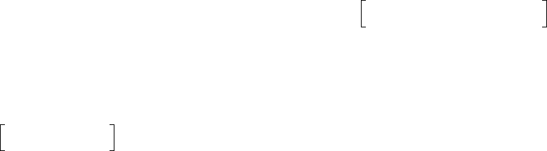
FIGURE 1.1 Quality factor as a function of linear energy transfer in water (L
).
Ch-01.fm Page 8 Friday, November 10, 2000 11:57 AM
Introduction 9
in the peripheral blood lymphocytes of exposed persons
is the most fully developed biological indicator of expo-
sure to ionizing radiation. By using a distribution analysis
of the aberrations, it is possible to estimate the proportion
of the body exposed and the average dose absorbed by the
irradiated fraction.
The influence of the microscopic distribution of the
absorbed energy on the detriment is taken into account by
the use of the quality factor, Q.
The ICRP [9] recommends the following approxima-
tions for the average value of Q:
• X-rays,
-rays and electrons: 1
• Thermal neutrons: 4.6
• Other neutrons: 20
• Protons and single-charged particles of unknown
energy and rest mass 1 : 10
•
-particles and multiple-charged particles of
unknown energy: 20
The dependence of
Q on LET is shown in Figure 1.1.
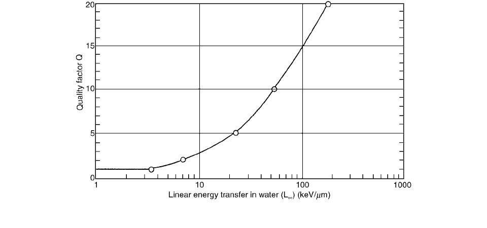
The RBE varies with the LET such that a hump-
shaped response curve is obtained. A generalized curve is
shown in Figure 1.2.
In order to produce a dicentric aberration, DNA damage
must be induced in the two unreplicated chromosomes
involved such that the damaged chromosomes can undergo
exchange.
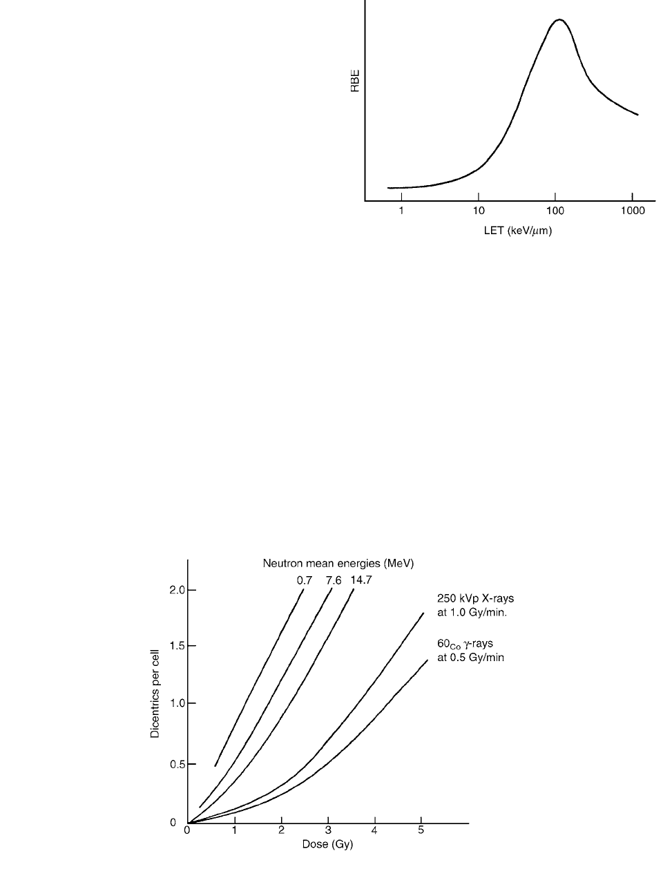
As the dose increases, the contribution of two track-
induced dicentrics will also increase. Thus, the dose-response
curve for X-ray-induced dicentrics will be a combination of
one- and two-track events, with the former being more fre-
quent at low doses and the latter being much more frequent
at high doses. The dose-response curve is generally assumed
to fit the equation
(1.67)
where Y is the yield of dicentrics, D is the dose,
is the
linear coefficient, and
is the dose-squared coefficient.
The dose-response curve for low LET radiation
(X-rays or
-rays) will be non-linear and best fit a linear-
quadratic model. The dose-response curve for high LET
radiation (for example, neutrons, protons, and
-particles)
will be linear, or close to linear. RBE increases with
increasing LET to a maximum of 100 keV/
m and
decreases at higher LET values as a result of overkill.
Figure 1.3 shows a selection of dose-response curves.
FIGURE 1.2 Generalized relationship between RBE and LET.
Y
D
D
2
FIGURE 1.3 The relationship between dicentric yield and acute exposure to several types of radiation.
Ch-01.fm Page 9 Friday, November 10, 2000 11:57 AM