Shani G. Radiation Dosimetry: Instrumentation and Methods
Подождите немного. Документ загружается.

90
Radiation Dosimetry: Instrumentation and Methods
the ionization chamber. p
Q
in Equation (3.1) replaces the
perturbation factor p
u
. The factor p
Q
is the product of the
various perturbation correction factors for the ion cham-
ber at quality Q, namely, p
wall
, p
cav
and p
cel
. The first two
factors correct for the lack of phantom equivalence of the
chamber wall and for the perturbation of the electron
fluence due to differences in the scattering properties
between the air cavity and the phantom, respectively. The
factor p
cel
corrects for the effect of the central electrode
of the chamber during in-phantom measurements. Rela-
tive values of p
Q
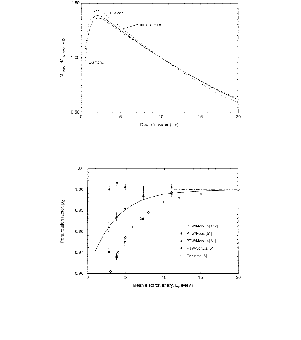
are shown in Figure 3.3.
The various steps between the calibration of ionization
chambers at the standards laboratories and the determina-
tion of absorbed dose to water at hospitals introduce
undesirable uncertainties into the realization of D
w
. [6]
Different factors are involved in the dosimetric chain that
starts with the quantity K
air
, measured in air using a
60
Co
beam, and ends with the absorbed dose to water measured
FIGURE 3.2 Relative depth-dose distributions obtained with a silicon diode, a diamond detector, and an ionization chamber (NE-
2561) in water using a 10-MV clinical photon beam. Results are normalized to unity at a depth of 10 cm. (From Reference [8]. With
permission.)
FIGURE 3.3 Variation of the perturbation factor p
Q
for several different plane-parallel chambers in common use, relative to the
NACP chamber, indicated by the dashed line drawn at
p
Q
1.00. All the measurements were made at the depth of dose maximum
and normalized to the quotient test chamber/NACP in a high-energy electron beam. The full line is a fit to three separate measurement
series on different accelerators using the P7W/Markus chamber. The filled data points are measurements on three different PTW
designs and renormalized so that
p
Q
1 for the NACP chamber; the unfilled symbols are for the Capintec-PS-033 chamber. (From
Reference [8]. With permission.)
Ch-03.fm(part 1) Page 90 Friday, November 10, 2000 11:58 AM
Ionization Chamber Dosimetry 91
in water D
W
, using clinical beams. Uncertainties in the
chain arise mainly from conversions performed by the user
at the hospital, for example, the k
m
and k
att
factors. The
transfer of N
K
(calibration factor) to N
D,air
(or N
gas
) means
that in practice the starting point of the calibration of clin-
ical beams already involves a considerable uncertainty.
Procedures to determine absorbed dose to water using
methods to measure appropriate base or derived quantities
have considerably improved at the Accredited Dosimetry
Laboratories. The required conversion and perturbation fac-
tors are available at some laboratories. These developments
support a change in the quantity used to calibrate ionization
chambers, i.e.,
N
K
, replacing it by a calibration factor in
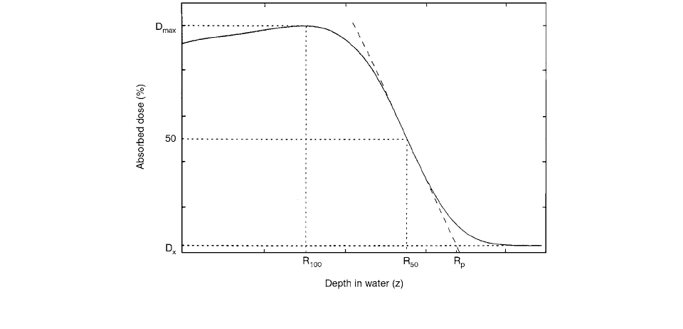
terms of absorbed dose to water. Electron beam depth close
distribution in water is shown in Figure 3.4.
The absorbed dose to water at the reference point of
the chamber in a phantom irradiated by a beam of refer-
ence quality Q
0
is given by the simple relationship
(3.2)
where is obtained at the standards laboratory from
the knowledge of the standard quantity absorbed dose to
water at the point of measurement in water for the calibra-
tion quality
Q
0
. A practical approach in common use is to
provide users with , i.e., calibration at the reference
quality
60
Co, and to apply beam quality correction factors
k
Q
for other beam qualities. For beams other than the ref-
erence quality, the absorbed dose to water is given by
(3.3)
where the factor k
Q
corrects for the difference between the
reference beam quality Q
0
and the actual quality being
used, Q. The value of k
Q
should ideally be determined
experimentally at the same quality as the user’s beam,
although this is seldom achievable.
A general expression which includes the ratio
(W
air
)
Q
/(W
air
)
Q
0
has been given in Reference [7]:
(3.4)
which can be used in any type of therapeutic beam. The
overall perturbation factors p
Q
and p
Q
0
include p
wall
, p
cav
,
p
cel
, and p
dis
as the reference point of a cylindrical ion
chamber in the center of the cavity volume. In therapeutic
electron and photon beams, the general assumption of
(
W
air
)
Q
(W
air
)
Q
0
yields the better known equation for k
Q
:
(3.5)
which depends only on ratios of stopping power ratios and
perturbation factors.
The connection between the
N
D,air
- and the N
D,w
-based
formalisms is established by the relationship
(3.6)
When a plane-parallel ionization chamber has a cali-
bration factor in terms of absorbed dose to water at a ref-
erence quality Q
0
, N
D,w,Q
0
, and the reference point positioned
at z
ref
, the absorbed dose to water at the reference depth is
given by
(3.7)
FIGURE 3.4 An electron beam depth-dose distribution in water showing the various range parameters.
D
w,Q
0
M
Q
0
N
D, w, Q
0
N
D, w, Q
0
N
D, w, Q
0
D
w, Q
M
Q
N
D, w, Q
0
k
Q
k
Q
s
w, air
()
Q
s
w, air
()
Q
0
---------------------
W
air
()
Q
W
air
()
Q
0
--------------------
p
Q
p
Q
0
--------
k
Q
s
w, air
()
Q
s
w, air
()
Q
0
---------------------
p
Q
p
Q
0
--------
N
D,
w,Q
N
D, air
s
w, air
()
Q
P
Q
D
w, Q
z
ref
() M
Q
N
D,w,Q
0
K
Q
Ch-03.fm(part 1) Page 91 Friday, November 10, 2000 11:58 AM

92 Radiation Dosimetry: Instrumentation and Methods
or, more explicitly,
(3.8)
The following steps and practical details, common
to the different methods to determine for plane-
parallel ionization chambers, are recommended: [8]
1. The long term stability and the leakage current
of the ionization chambers and the electrometer
should be checked before the measurements for
the determination of .
2. Sufficient time should be allowed for the
ionization chamber, build-up cap, and phan-
tom material to reach equilibrium with the
room temperature and for the electrometer
to stabilize.
3. The time during which the chambers and the
build-up cap material are handled with bare hands
should be minimized.
4. The reference chamber (when applicable) should
be positioned with its recommended orientation
in the radiation beam (the reference orientation
should be stated in the calibration certificate).
5. The ambient air pressure and the temperature in
the air or in the phantom, depending on the type
of measurement, should be measured before,
during, and after the irradiation measurements,
and corrections should be applied to the reading
of the detectors for any variations. In the case
of using a phantom, the temperature should be
measured inside the phantom material.
6. Before the first reading of each series of mea-
surements is taken, the chambers placed inside
TABLE 3.3
Recommended Values of for Plane-Parallel Chambers in
Various Phantom Materials Irradiated by A
60
Co Gamma-Ray Beam
Chamber type
Phantom Material
Water PMMA Polystyrene Graphite
Capintec PS-033 0.989 0.982 0.960
a
0.989
Exradin P11 — 1.000
a
— —
Holt Pancake — — 1.000
a
—
NACP 1.024 1.012 1.000 1.027
PTW/Markus M23343 1.009 1.006 0.979 1.013
PTW/Schulz M23346 l.001 1.001 0.992 1.009
Roos FK-6 1.003
b
— — —
Source: From Reference [8]. With permission.
p
wall
pp
TABLE 3.4
Ratios of Stopping Powers (s
med, air
) and Mass
Energy Absorption Coefficients ((
en
/
)
med,air
) for
60
Co Gamma-Rays
Chamber Wall or
Phantom Material
s
med.air
Water 1.133 1.112
PMMA 1.102 1.081
Polystyrene 1.110 1.078
Graphite 1.002 1.001
A- 150 1.142 1.101
C-552 0.995 1.001
Delrin 1.080 1.068
Nylon 1.142 1.098
Note: (To evaluate , use ( ).
Source: From Reference [8]. With permission.
(
en
)
med, air
en
()
med
1
,med
2
en
()
med
1
,air
en
()
med
2
,air
D
w,Q
z
ref
()M
Q
N
D,w,Q
0
s
w,air
()
Q
s
w,air
()
Q
0
---------------------
p
cav
p
wall
()
Q
p
cav
p
wall
()
Q
0
------------------------------
N
D, air
pp
N
D, air
pp
TABLE 3.5
Recommended Values of k
att
,k
m
, Needed for
60
Co In-Air Calibration of Parallel-Plate
Chambers
Chamber
Build-up Cap
Material
k
att
k
m
Capintec PS-033 polystyrene 1.012
b
Exradin P11 polystyrene 0.973
Holt Pancake polystyrene 0.980
PTW Markus PMMA 0.985
NACP graphite 0.975
Roos FK-6 PMMA or water N/A
Note: (The build-up caps are of the material as shown in
Column 2 and the additional build-up cap thickness is 0.5 g
cm
2
, except for the Holt chamber, which comes with a build-
up cap.)
Source: From Reference [8]. With permission.
Ch-03.fm(part 1) Page 92 Friday, November 10, 2000 11:58 AM
Ionization Chamber Dosimetry 93
the phantom or equipped with the build-up cap
should be pre-irradiated with 2 to 5 Gy to
achieve charge equilibrium.
7. For each chamber, five independent determina-
tions of should preferably be made and
the mean value should be used.
8. The for the reference chamber is deter-
mined from
(3.9)
where is the air-kerma calibration factor of the ref-
erence chamber provided by the standards laboratory,
(1
g) 0.997 (for
60
Co gamma-rays).
Parameters related to several ionization chambers are
listed in Tables 3.3, 3.4, and 3.5.
II. CORRECTION FACTORS
Ionization chambers calibrated with either a
60
Co gamma
source or in high-energy electron beam plane-parallel and
cylindrical chambers are compared in the calibration cor-
rection and must therefore be made to obtain the right dose.
The main purpose of the correction factors is to allow
calibration procedures more widely practicable than those
based on the use of an electron beam of sufficiently high
energy. The condition required to apply the correction
factors is that the characteristics of the chambers to be
calibrated are the same as those reported for the chambers
considered in the investigation.
A. PLANE-PARALLEL IONIZATION CHAMBERS
Correction factors for calibration of plane-parallel ioniza-
tion chambers with a
60
Co gamma-ray beam were investi-
gated by Laitano et al. [9] Correction factors for free-in-air
calibration were measured as follows. The plane-parallel
chambers were irradiated free in air, in a
60
Co gamma-ray
beam of given size with a build-up disc and with their air
cavity center at a point where the air kerma, K
air
, was
known at that point the absorbed dose to the air in the
cavity of the plane-parallel chamber with its build-up disc
is given by
(3.10)
where M
c,pp
is the plane-parallel chamber reading at the
calibration conditions considered; (k
pp
)
1,2
, is the plane-
parallel chamber correction factor for the conditions A
1
and A
2
, and N
D,pp
is the plane-parallel chamber calibration
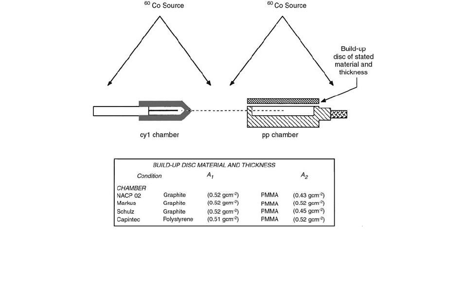
factor (details in Figure 3.5). The reading M
c,pp
is corrected
for ambient para-meters, for ion recombination, and for
polarity effect. For a plane-parallel chamber, the correc-
tion factors (k
pp
)
1,2
can be obtained from Equation (3.10)
if the N
D,pp
factor of that chamber is already known.
N
D, air
pp
N
D, air
ref
N
D, air
ref
N
K
ref
1 g()k
att
k
m
k
cel
N
K
ref
D
air
()
cav
K
air
1 g()k
pp
()
A
1, 2
M
c, pp
M
D, pp
FIGURE 3.5 Experimental conditions A
1
and A
2
: free-in-air calibration, build-up material density: 1.73 g cm
3
(graphite), 1.18 g
cm
3
(PMMA), and 1.04 g cm
3
(polystyrene). The disc diameter was equal to the chamber external diameter. In the Schulz chamber
characterized by a thin backwall, two discs were used on the front and rear of the chamber, respectively. (From Reference [9]. With
permission.)
Ch-03.fm(part 1) Page 93 Friday, November 10, 2000 11:58 AM
94 Radiation Dosimetry: Instrumentation and Methods
By equating the expressions of the absorbed dose relevant
the plane-parallel and to the cylindrical chamber, the fac-
tor N
D,pp
can be obtained by
(3.11)
where
M
u,cyl
and M
u,pp
are the corrected readings, at the
electron-beam irradiation conditions, of the reference
cylindrical chamber and of the plane-parallel chamber,
respectively. (p
u,cyl
)
eb
refers to the cylindrical chamber and
is the correction factor due to the electron fluence pertur-
bation. N
D,cyl
is the calibration factor of the reference cylin-
drical chamber, given by the expression:
(3.12)
where M
c, cyl
is the corrected reading of the reference cylin-
drical chamber in the
60
Co gamma-ray calibration condi-
tion, and k
m
and k
att
are the factors that take into account
the lack of air equivalence of ionization chamber material
and the attenuation and scattering of the
60
Co photons in
the chambers wall, respectively. From Equation (3.10) one
finds
(3.13)
Combining these equations, one obtains
(3.14)
Correction factors for calibration at d
max
in PMMA
and in polystyrene phantoms have been found as follows.
The plane-parallel chambers were irradiated in a
60
Co
gamma beam with the center of their air cavity at d
max
in
PMMA and polystyrene phantoms. The K
air
value at the
position of the plane-parallel chamber center in the
absence of chamber and phantom was known. At this
reference point the
60
Co beam size was 10.5 10.5 cm
2
.
In this experimental condition, an expression similar to
Equation (3.10) holds:
(3.15)
Here the chamber reading M
c, pp
now includes the addi-
tional contribution due to the radiation scattered by the
phantom into the chamber cavity, and (k
pp
)
B
1,2
is the plane-
parallel chamber correction factor for the conditions B
1
and B
2
. [9] From Equation (3.15) one finds
(3.16)
Combining with Equations (3.11) and (3.12) will give
(3.17)
For correction factors for in-phantom calibration at a given
depth, the correction factors of the plane-parallel cham-
bers were determined in phantoms of different materials
and at a given depth where the absorbed dose to the phan-
tom medium was known.
The correction factor can be expressed as
(3.18)
(3.19)
The calibration depth was 5 cm in PMMA, polystyrene,
and water (see Figure 3.6).
Plane-parallel ionization chambers are often cali-
brated at the clinic against a cylindrical chamber in a
high-energy electron beam. If the perturbation due to the
presence of the plane-parallel chamber in a water phantom
at the calibration quality (i.e.,
60
Co) is known, a straight-
forward dose-to-water calibration is possible. If the per-
turbation as a function of photon-beam quality is known,
the plane-parallel chamber might be used for all radiation
qualities. [10]
A number of uncertainties may be added to the N
D,pp
factor for the plane-parallel chamber:
1. Any uncertainties in the clinic’s cylindrical
chamber calibration are transferred to the plane-
parallel dosimetry.
2. The two chambers must be irradiated at
slightly different positions or at the same posi-
tion but at different times. In the former case
an inhomogeneous dose distribution within the
field will cause a difference in the dose deliv-
ered, and in the latter case a very stable dose-
monitoring device is needed to avoid influence
of accelerator output fluctuations.
3. Most cylindrical chambers are not of a homo-
geneous design, but they all have a central elec-
trode made of aluminium. A p
cel
factor must
then be introduced into the calculations to take
into account the disturbance of the electrode in
the electron beam relative to the
60
Co-gamma-
ray beam. The size of the p
cel
factor for com-
monly used cylindrical chambers is being
debated and has been the subject of some recent
papers. [10]
4. If a plastic phantom is used, which is often
the case, charge build-up in the plastic may
N
D, pp
M
u,cyl
N
D,cyl
p
u,cyl
()
eb
M
c, pp
-------------------------------------------------
N
D, cyl
K
air
1 g()k
m
k
att
M
c, cyl
------------------------------------------
k
pp
()
A
1,2
M
c, pp
N
D, pp
K
air
1 g()
----------------------------
k
pp
()
A
1,2
M
c, pp
M
u,cyl
M
c,cyl
M
u, pp
---------------------------
k
m
k
att
p
u, cyl
()
eb
K
air
1 g()k
pp
()
B
1, 2
M
c, pp
N
D, pp
k
pp
()
B
1, 2
M
c, pp
N
D, pp
K
air
1 g()
----------------------------
k
pp
()
B
1, 2
M
c, pp
M
u, cyl
M
c, cyl
M
u, pp
----------------------------
k
m
k
att
p
u, cyl
()
eb
p
u, pp
()
C
1, 2, 3, 4
M
c, cyl
N
D, cyl
p
u cyl,
()
c
M
c, pp
N
D, pp
-------------------------------------------------
p
u, pp
()
C
1, 2, 3, 4
M
c,cyl
M
u, pp
p
ucyl,
()
c
M
c, pp
N
u, cyl
p
ucyl,
()
eb
------------------------------------------------
Ch-03.fm(part 1) Page 94 Friday, November 10, 2000 11:58 AM

Ionization Chamber Dosimetry 95
introduce a disturbance in the measurement. The
h
m
factor—the ratio of the measured signal at
dose maximum in water to that measured in the
phantom material—may be not only phantom
material–dependent but also chamber type–
dependent, thus yielding different h
m
factors for
the plane-parallel and cylindrical chambers.
The cylindrical and plane-parallel chambers were
calibrated by Nystrom and Karlsson [10] against the
Fricke dosimeter in a high-energy electron beam and in
four different photon beams, including
60
Co
-rays. Sim-
ilar plane-parallel chambers were included in the study
(Figure 3.7).
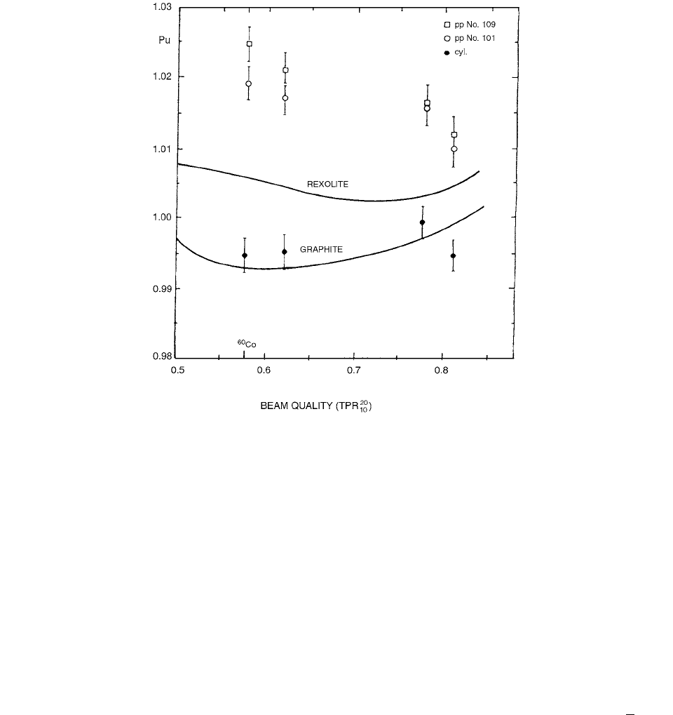
The p
u, pp
factors are shown in Figure 3.8; the P
u
values
for the two NACP chambers are plotted against for
the photon beams. The full lines indicate the p
u
values for
polystyrene and graphite, with chamber wall thickness
equal to that of the entrance window of the NACP cham-
bers and the walls of the cylindrical chambers, i.e., 0.5 mm.
In some situations, especially for the calibration of
low-energy electron beams, where parallel-plate chambers
are recommended for the determination of absorbed dose
at the reference point, solid plastic phantoms may, for
FIGURE 3.6 Experimental conditions C
1
,C
2
,C
3
, and C
4
: calibration at a given depth in phantoms of different materials (PMMA,
polystyrene, water, and graphite). The calibration depth
d was 4.45 g cm
2
in graphite and 5 cm in other phantoms. With regard to
the cylindrical chamber position, the figure refers to measurements in water, polystyrene, and PMMA, for which the
P
eff
approach
was used. For measurements in the graphite phantom, the cylindrical chamber was positioned with its center at depth
d, then correcting
the reading by the
P
repl
factor. (From Reference [9]. With permission.)
TPR
10
20
FIGURE 3.7 Principal view of the NACP chamber. (From Ref-
erence [10]. With permission.)
Ch-03.fm(part 1) Page 95 Friday, November 10, 2000 11:58 AM
96 Radiation Dosimetry: Instrumentation and Methods
practical reasons, be used. Corrections are then required
to obtain the absorbed dose to water at a reference point
situated at an equivalent depth in water. [11]
Scaling factors have often been based on R
csda
, the
linear continuous-slowing-down range; this quantity, how-
ever, does not include differences in multiple scattering
between the two materials, which might play an important
role at low electron energies, where plastic phantoms are
more commonly used.
An additional correction factor is needed to account
for differences in the magnitude of the primary electron
fluence in water and in the solid material at equivalent
depths due to the different scattering properties of the
phantom materials. The AAPM protocol (1994) [14] pro-
vides an electron fluence factor, denoted by the symbol
, evaluated analytically from the Fermi-Eyges theory
of multiple scattering. To determine this fluence factor
experimentally a perturbation free chamber is needed.
IAEA TRS-277 [4] used the factor
h
m
, first suggested
by NACP (1981) [4a] and defined according to IAEA as
the ratio of the signal measured using a plane-parallel
chamber at the ionization maximum on the central axis in
a water phantom to that measured (at the same source to
phantom surface distance) for the same accelerator mon-
itor setting at the ionization maximum in other phantom
materials. The new IAEA code of practice, IAEA TRS-
381, [8] assumes that the
h
m
-factor is approximately equal
to . The equality between the factors and h
m
is based on the assumption of a perturbation free chamber,
and any departure from these assumptions would make
the set of data dependent on the chamber used. [11]
According to the IAEA TRS-381 protocol, the
absorbed dose to water when measurements are performed
in a solid plastic phantom is obtained using the equation
(3.20)
where N
D,air
is the absorbed-dose-to-air chamber factor.
From the quantity determined with this factor, , the
absorbed dose to water at a point D
w
is derived by the
application of the Bragg-Gray principle. M
Q,plastic
is the ioni-
zation measured in the solid plastic phantom, corrected
for influence quantities (p, T, recombination, etc.). (s
w,air
)
Q
is the stopping power ratio for water to air, p
Q
is the overall
perturbation factor including both cavity (replacement)
perturbation and wall effects, and h
m
is the correction
factor to account for differences in the magnitude of the
primary electron fluence in water and in the solid material
at equivalent reference depths, due to the different scat-
tering properties of the phantom materials.
FIGURE 3.8 The Pu,pp factors as functions of photon beam quality for the investigated chambers. Error bars indicate SD. The
full line indicates
Pu,cyl factors for polystyrene and graphite derived with wall thickness of 0.5 mm, the thickness at the entrance
window of the NACP chambers and wall thickness of the chambers investigated. From Reference [10]. With permission.
med
wate
r
med
water
med
water
D
wQ,
M
Q plastic,
N
Dair,
s
wair,
()
Q
p
Q
h
m
D
ai
r
Ch-03.fm(part 1) Page 96 Friday, November 10, 2000 11:58 AM

Ionization Chamber Dosimetry 97
Both IAEA TRS-381 and the new UK-protocol
(IPEMB) [12] define h
m
as the ratio of electron fluences
at equivalent depths in the water and plastic phantoms. If
a criterion is applied where perturbation factors in water
and plastic differ, the experimental determination of the
factor h
m
should strictly be modified according to
(3.21)
where the ratio of perturbation factors for the chamber
used in the measurements appears explicitly for the two
media. is the ratio of the electron fluences as noted
by AAPM Task Group 21. [13]
AAPM Task Group 39 [14] has presented a different
approach. Instead of calculating the dose to water directly,
these protocols determine first the dose to the plastic phan-
tom using the equation
(3.22)
where M is the electrometer reading in the solid plastic
phantom, corrected for pressure and temperature. is
the cavity gas calibration factor, is the mean
restricted mass stopping power of plastic to gas, P
ion
the
correction for ion recombination, P
repl
the perturbation
replacement factor, and P
wall,plastic
the perturbation wall fac-
tor in the plastic medium.
The dose to water is then obtained in a second step
by scaling the electron fluence in water and the solid
phantom by the relation [11]
(3.23)
where is the fluence factor, i.e., the ratio of electron
fluence in water to that in the solid phantom at equivalent
depths, and ( )
coll
is now the mean unrestricted mass
stopping power ratio.
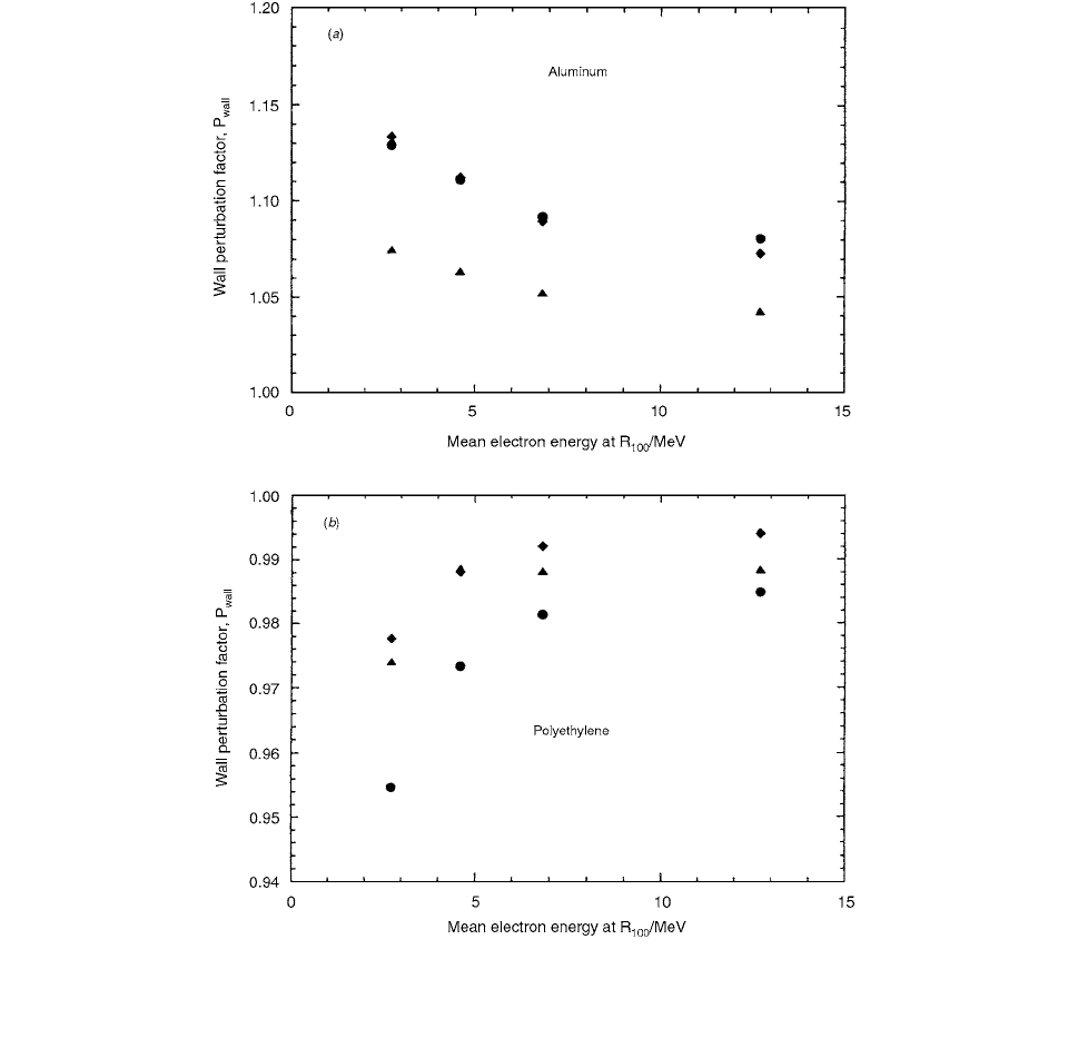
Figure 3.9 shows the measured P
wall
factors as a func-
tion of energy for the simulated Attix, Roos, and NACP
chambers placed in phantoms of aluminum (Figure 3.9a)
and polyethylene (Figure 3.9b). These materials are not
typical for clinical dosimetry but have atomic numbers
that differ significantly from the chamber wall materials
and thus illustrate wall effects more clearly. [11]
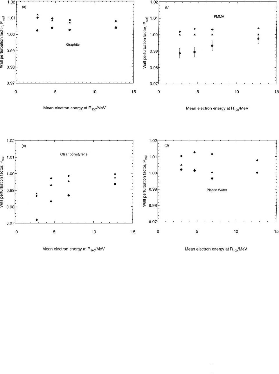
Figure 3.10 shows the P
wall
-factors for graphite,
PMMA, clear polystyrene and Plastic Water™. These
phantom materials are closer to the wall materials with
respect to atomic number and scattering effects and, there-
fore, the P
wall
-factors are also closer to unity. The NACP
chamber is recommended to be used with a PMMA phan-
tom. At low electron energies where plastic phantoms are
normally used, it can be seen in Figure 3.10 that the
P
wall
-
factor is 0.99. The Roos chamber has a P
wall
-factor equal
to unity in a PMMA phantom. Figure 3.10 also shows that
the P
wall
-factor for the Attix chamber in PMMA is close
to 1.00, as the backscatter in PMMA and Solid Water™
are similar. In a clear polystyrene phantom, the P
wall
-fac-
tors are below unity for all chambers, especially for the
NACP chamber, where a P
wall
-factor of 0.97 was obtained
at low energies. Also, the Attix and Roos chambers have
P
wall
-factors below 0.99 at low energies.
B. k
Q
FACTORS
k
Q
, the beam quality correction factor, corrects the
absorbed dose-to-water calibration factor N
D,w
in a refer-
ence beam of quality Q
0
to that in a user’s beam of quality
Q
1
. It was discussed by Vatnitsky et al. [15]
If an ionization chamber with a
60
Co absorbed dose-
to-water calibration (reference beam, quality Q
0
) is used
for measurements in a beam with quality Q
1
, the absorbed
dose-to-water D
w
(Q
1
) is given by (rewriting Equation 3.3)
(3.24)
where
M
Q
is the charge collected in the ionization chamber
in the beam Q
1
corrected to reference temperature and
pressure conditions and for ionic recombination; N
D,w,
is
the absorbed dose-to-water calibration factor in the
60
Co
beam; and k
Q
corrects the reference absorbed dose-to-
water calibration factor N
D,w,
to the beam with quality Q
1
.
The subscript
is placed on k
Q
to specify that the refer-
ence beam is the
60
Co beam. The term ‘‘quality” is used
to specify the radiological properties of the beam.
For photons, the quality is specified in terms of the
and, for electrons, in terms of the depth of 50%
dose in water. The beam quality specifier for a proton
beam is the effective energy of the protons at the calibra-
tion point.
Water calorimetry was used as the absolute dose stan-
dard to measure k
Q
, employing the water calorimeter devel-
oped by R. Schulz. [16]
The dose delivered to the water for irradiation within
a reference beam of quality Q
0
(
60
Co beam) was deter-
mined from
(3.25)
where
c is the specific heat of water at the calorimeter
operation temperature,
is the calibration factor obtained
from the thermistor calibrations, V
0
is the bridge deflec-
tion, and D
T
is the thermal defect.
Vatnitsky et al. determined k
Q
by treating the calo-
rimeter response to the irradiation as a deflection of the
Wheatstone bridge. When the water calorimeter was
replaced with a water phantom, the absorbed dose to water
measured by an ionization chamber in the same beam Q
0
was given by
(3.26)
h
m
exp
med
water
p
Qmed,
p
Qw,
med
water
D
med
MN
gas
pp
L
()
gas
med
P
ion
P
repl
P
wall plastic,
N
gas
pp
L
()
D
med
d
water
()D
med
d
med
()S
()
coll
[]
med
water
med
water
med
water
S
D
w
Q
1
() M
Q
1
N
Dw
,,
k
Q
TPR
10
20
D
water
Q
0
cal,()c
V
0
1 D
T
()
D
water
Q
0
ion,()N
Dw
,,
M
0
Ch-03.fm(part 1) Page 97 Friday, November 10, 2000 11:58 AM
98 Radiation Dosimetry: Instrumentation and Methods
where N
D,w,
is the ionization chamber absorbed-dose-to-
water calibration factor in a reference
60
Co beam Q
0
and
M
0
is the charge collected in the ionization chamber, cor-
rected to the reference temperature and pressure and for
recombination.
Using the following equation, the dose measured by
the calorimeter was then related to the dose measured in
the dummy calorimeter with an ionization chamber:
(3.27)
Because of the slight geometrical differences between
water and dummy calorimeters, a correction factor for
inverse square and attenuation C
0
(IS, Att) was applied
to the dummy calorimeter data in a
60
Co beam. The beam
quality correction factor, k
Q
, relates calibration factors in
a beam with a quality Q
1
to that in a beam with a quality
Q
0
. For measurements in a proton beam with a quality Q
1
,
Equations (3.25)–(3.27) were rewritten as
(3.28)
(3.29)
(3.30)
where
C
1
(IS) includes only inverse square corrections,
since attenuation corrections in the plateau region and at
FIGURE 3.9 Wall perturbation factors at the depth of ionization maximum for the simulated Attix (), NACP (•), and Roos ()
chambers as a function of the mean electron energy; (a) phantom material: aluminum, (b) phantom material: polyethylene. (From
Reference [11]. With permission.)
D
water
Q
0
cal,()D
water
Q
0
ion,()C
0
IS Att,()
D
water
Q
1
cal,()c
V
1
1 D
T
()
D
water
Q
1
ion,()N
Dw
,,
M
1
k
Q
D
water
Q
1
cal,()D
water
Q
1
ion,()C
1
IS()
Ch-03.fm(part 1) Page 98 Friday, November 10, 2000 11:58 AM
Ionization Chamber Dosimetry 99
the spread-out Bragg peak of the proton beam are very
small to be counted. Equations (3.25)–(3.30) were solved
for k
Q
to reveal [15]
(3.31)
To provide a comparison with measured values, the
proton beam quality correction factors
k
Q
were calculated
for both the PTW and Capintec chambers, employing
equations discussed elsewhere. The k
Q
values were
derived from ratios of absorbed doses to water in two
beams using standard dosimetry protocols. Absorbed dose
to water in a proton beam was calculated using an assump-
tion that the protons interact only with the gas of the ion-
ization chamber and wall effects are ignored. The mass
stopping power ratio of water to air was derived for the
effective energy of protons at the measurement depth. This
energy was determined using the European Hearg Particle
Dosimetry Group (ECHED) [17] recommendations.
Absorbed dose to water in a reference
60
Co beam was cal-
culated using the TG 21 protocol. The resulting equation is
given by
(3.32)
FIGURE 3.10 Wall perturbation factors at the depth of ionization maximum for the simulated Attix (), NACP (•), and Roos ()
chambers as a function of the mean electron energy; (a) phantom material: graphite, (b) phantom material: PMMA, (c) phantom
material: polysterene, (d) phantom material: Plastic Water
TM
. (From Reference [11]. With permission.)
k
Q
V
1
V
0
----------
M
0
M
1
-------
C
0
IS Att,()
C
1
IS()
----------------------------
k
Q
W
pr air,
W
air,
----------------
S/
()
air
w
[]
Q
1
L/
()
air
w
[]
Q
0
----------------------------
p
air
w
[]
Q
1
p
air
w
[]
Q
0
------------------
Ch-03.fm(part 1) Page 99 Friday, November 10, 2000 11:58 AM