Shani G. Radiation Dosimetry: Instrumentation and Methods
Подождите немного. Документ загружается.

110 Radiation Dosimetry: Instrumentation and Methods
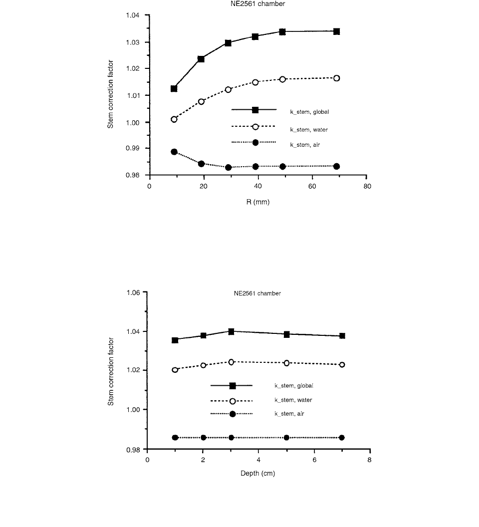
There is a slight dependence of the stem effect on the
depth of the chamber center in the phantom. Figure 3.23
shows that, for an NE2561 chamber irradiated at various
depths in water by a parallel 70-kV photon beam with a
100-cm
2
field, k
stem,water
increases with depth for d 2 cm.
The variation of k
stem,water
becomes negligible for larger
depths. The statistical uncertainty in the calculated stem-
effect corrections was about 0.2%.
III. BUILD-UP CAP AND BUILD-UP REGION
The absorbed dose to a point within a phantom can be
divided into two components: a part due to primary radi-
ation and a part carried by photons scattered in the treat-
ment head reaching the point of interest. The use of head
scatter may be incorporated into different sets of dosimetric
calculation models in external-beam radiotherapy.
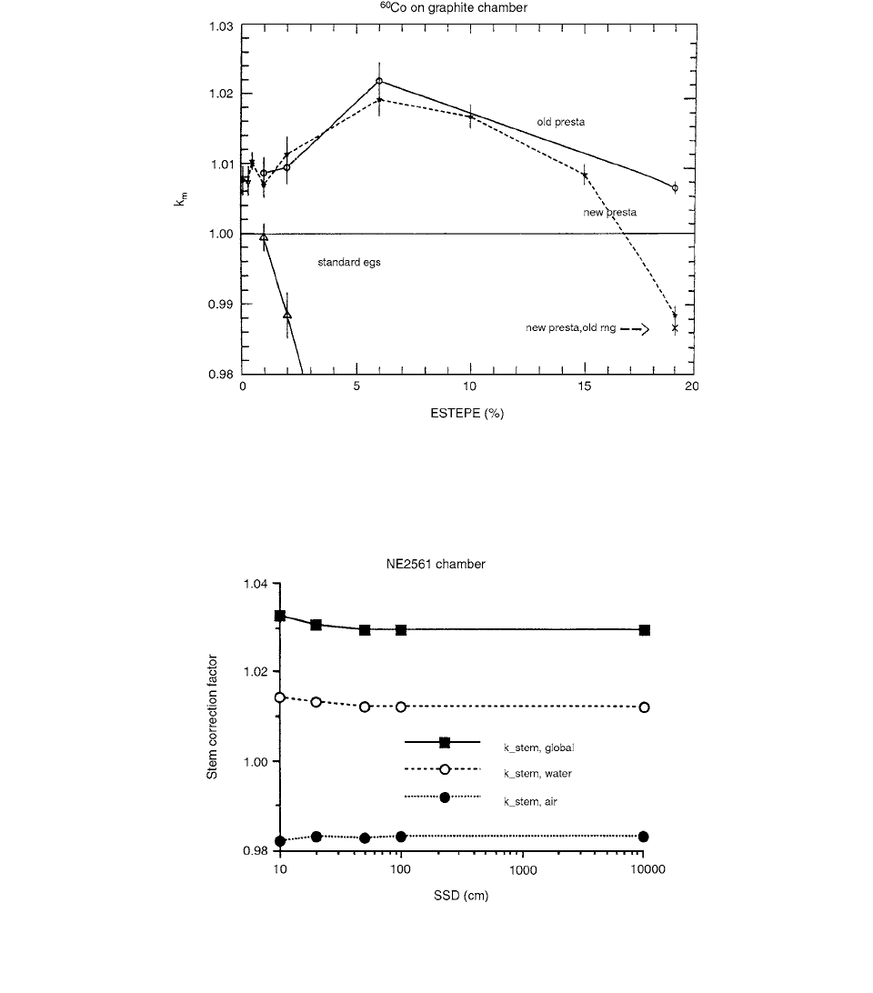
FIGURE 3.20 Variation in calculated value of k
m
as a function of maximum continuous energy loss per electron step (ESTEPE
in %) for a graphite-walled ion chamber irradiated by a parallel beam of 1.25-MeV photons. The horizontal line corresponds to
the predictions of Spencer-Attix cavity theory given in Table 3.8. Default step-size algorithm results are shown with ESTEPE
19%. (From Reference [27]. With permission.)
FIGURE 3.21 The variation of the stem correction factors, k
stem,air
and k
stem,global
, with SSD for an NB2561 chamber used at 3-cm
depth in water irradiated by a point source of 100-kV photons. The field size was 3 cm in radius. The statistical uncertainty is within
0.1% for
k
stem,air
and about 0.2% for k
stem,water
and k
stem,global
. (From Reference [28]. With permission.)
Ch-03.fm(part 1) Page 110 Friday, November 10, 2000 11:58 AM
Ionization Chamber Dosimetry 111
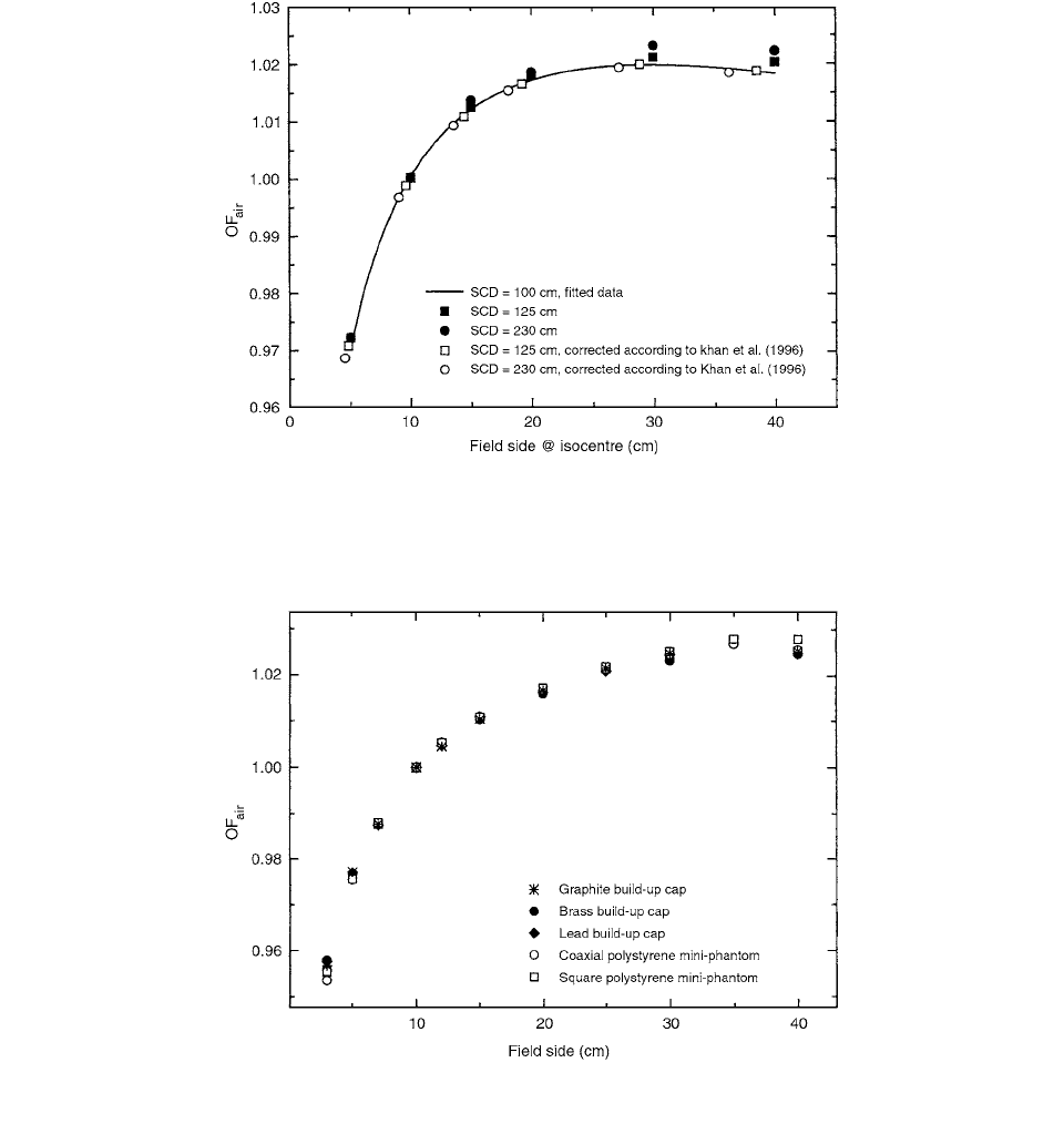
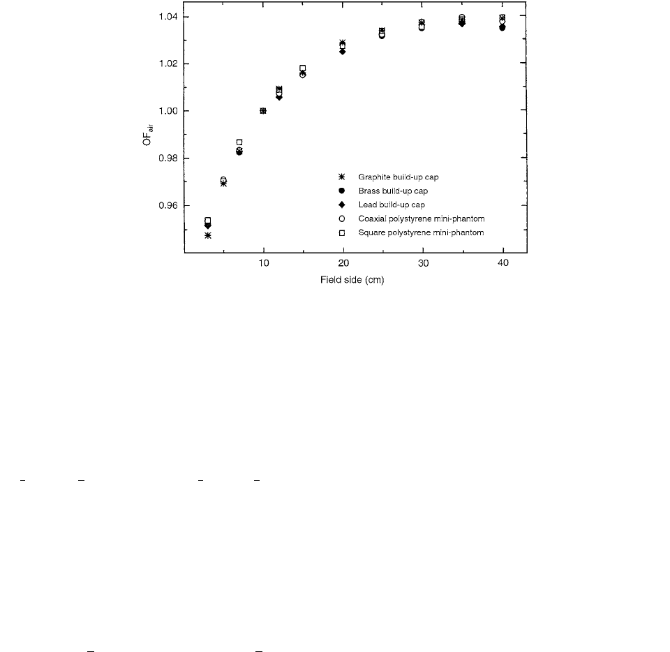
The suitability of high-Z materials as build-up caps
for head-scatter measurements has been investigated by
Weber et al. [29] Build-up caps are often used to enable
characterization of fields too small for a mini-phantom.
The results show that the use of lead and brass build-up
caps produces normalized head-scatter data slightly dif-
ferent from graphite build-up caps for large fields at high
photon energies. At lower energies, however, no signifi-
cant differences are found. The intercomparison between
the two different plastic mini-phantoms and graphite caps
shows no differences.
The determination of the head-scatter factor, S
c
, is
usually done by in-air measurements with sufficient mate-
rial surrounding the detector to prevent contaminating
secondary particles from reaching the detector volume and
to provide enough charged particles for signal strength.
FIGURE 3.22 The variation of the stem correction factors, k
stem,air
, k
stem,water
, and k
stem,global
with field size for an NE2561 chamber
used at 3-cm depth in water irradiated by a point source of 100-kV photons with a 50-cm SSD. The statistical uncertainty is within
0.1% for
k
stem,air
and about 0.2% for k
stem,water
and k
stem,global
. (From Reference [28]. With permission.)
FIGURE 3.23 The variation of the stem correction factors, k
stem,air
, k
stem,water
, and k
stem,global
with the depth of the chamber center in
water for an NE2561 chamber irradiated by a parallel beam of 70-kV photons with a 100-cm
2
field. The statistical uncertainty is
within 0.1% for
k
stem,air
and about 0.2% for k
stem,water
and k
stem,global
. (From Reference [28]. With permission.)
Ch-03.fm(part 1) Page 111 Friday, November 10, 2000 11:58 AM
112 Radiation Dosimetry: Instrumentation and Methods
Head-scatter factors may also be derived from phantom
measurements. [30] However, two main methods have
evolved for the measurements of head scatter. The first
method incorporates build-up caps of tissue-equivalent
materials such as different plastics or graphite. When
higher-energy beams became available, it became evident
that materials of low density resulted in caps of substantial
dimensions as compared with small field sizes. As a result,
interest turned to materials of higher density, e.g., alumi-
num, brass, or lead.
The caps were used on a 0.6-cm
3
BF-type ionization
chamber (NE 2571, Nuclear Enterprise, UK) with a
graphite wall and connected to an electrometer. The ion-
ization chamber was operated at +360 V. Another ioniza-
tion chamber used was a 0.12-cm
3
RK chamber (RK 83-
05, Scanditronix, Sweden) connected to the electrometer
and operated at 360 V. The influence of the direction of
the ionization chamber, i.e., parallel or perpendicular to
the radiation beam, was investigated in order to quantify
any influence of stem and cable effects on the measure-
ments. Both ionization chambers, equipped with a build-
up cap, were checked for these effects at 4 and 18 MV
for the BF-type and at 4 MV for the RK ionization
chamber.
The normalized head-scatter factor, or output factor
in air,
OF
air
, in the terminology of the treatment planning
system is defined as
(3.54)
where (
/M)
calib
is the energy fluence per monitor unit on
the central axis in the calibration situation, i.e., 10 cm
10 cm, and (/M)
test
is the energy fluence per monitor
unit in the beam of interest.
A problem arises when the outer dimensions of the
build-up caps or the mini-phantom approach the field
size at the isocenter. The normalized head-scatter factor
is valid only if the amount of scattering material sur-
rounding the detector, and contributing to the signal, is
kept constant, i.e., is not obscured by the radiation field.
For very small field sizes, this is not possible and the
measurements must be performed at an extended Source
Chamber Distance (SCD). Other investigators have
shown that the head-scatter factor is independent of SCD.
Figures 3.24 and 3.25, indicate that this is not the case
at higher energies.
If the detector is moved away from the isocenter, the
solid angle of the flattening filter and thus the amount of
OF
air
/M()
test
/M()
calib
----------------------------
TABLE 3.9
Physical Data for the Build-up Caps
Wall Thickness
(mm)/(g cm
2
)
Material
Density
(g cm
3
)
Low-energy
(4.6 MV)
High-energy
(10.18 MV)
Graphite 1.863 11.3/2.1 36.0/6.7
Brass 8.455 2.5/2.1 7.9/6.7
Lead 11.200 1.9/2.1 6.0/6.7
Source: From Reference [29]. With permission.
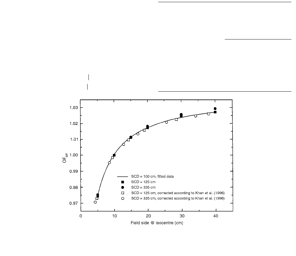
FIGURE 3.24 Head-scatter measurements at 4 MV with brass build-up cap measured at SCD 100, 125, and 335 cm. The data
at SCD
100 cm have been fitted to a polynomial. Open symbols are corrected values according to Khan el al. [31] (From Reference
[29]. With permission.)
Ch-03.fm(part 1) Page 112 Friday, November 10, 2000 11:58 AM
Ionization Chamber Dosimetry 113
filter, as viewed by the detector, decreases. [31] However,
as data are normalized to a 10 cm 10 cm field, the
smaller fields may be covered by measuring at extended
distances without introducing any large errors. Measured
head-scatter data at extended distances have been recal-
culated to SCD 100 cm with an equivalent field size
according to Khan et al. [31], assuming the flattening filter
to be the single largest source of head scatter. Good agree-
ment with the data measured at SCD 100 cm was found
(see Figures 3.24 and 3.25). [29]
The measured output factors for two beam qualities
are shown in Figures 3.26 and 3.27. At lower energies, no
significant differences were found between the different
build-up caps and mini-phantoms. However, as the energy
increases, the differences between the low- and high-Z
materials increase and the largest discrepancies were
found at 18 MV for large field sizes.
The effect of build-up cap materials on the response
of an ionization chamber to
60
Co gamma-rays was mea-
sured by Rocha et al. [32]
FIGURE 3.25 Head-scatter measurements at 18 MV with brass build-up cap measured at SCD 100, 125, and 230 cm. The data
at SCD
100 cm have been fitted to a polynomial. Open symbols are corrected values according to Khan el al. [31] (From Reference
[29]. With permission.)
FIGURE 3.26 Head-scatter measurements for a CLINAC 600C, 4 MV. (From Reference [29]. With permission.)
Ch-03.fm(part 1) Page 113 Friday, November 10, 2000 11:58 AM
114 Radiation Dosimetry: Instrumentation and Methods
The equations relating to the exposure calibration fac-
tor (N
X
) for the cavity absorbed dose calibration factor
(N
gas
or N
D
) are given by
AAPM:
(3.55)
SEPM: (3.56)
(3.57)
(3.58)
where (
k
s
)c and (k
st
)c are correction factors to allow for
lack of saturation of charge collection and for stem irra-
diation at the calibration quality, respectively. The notation
used in the above equations is in accordance with the
appropriate protocols. A comparison of Equations (3.55),
(3.56), and (3.57) shows that (a) the correction factor for
the attenuation and scattering in the ion chamber wall and
build-up cap is
and (b) the non-equivalence to air is taken into account
by the k
m
factor or by the denominator of Equation (3.55).
The attenuation and scattering correction in the chamber
and build-up cap in the calibration beam can be calculated
from the equation [33]
(3.59)
where
t is the total wall thickness in g cm
2
and
is the
attenuation and scattering fraction per wall thickness unit.
The measurements were performed with the ÖFS ion-
ization chamber model TK 01 (secondary standard therapy
level) with a 0.5-mm thick Delrin (CH
2
O)
n
wall, with its
inner side coated with a mixture of graphite (15%)/alu-
mina (85%) powder and epoxy resin in the ratio 1 (pow-
der): 3 (resin). The whole thickness was estimated to be
10
2
mm. The central electrode, build-up cap, and stem
were also made of Delrin.
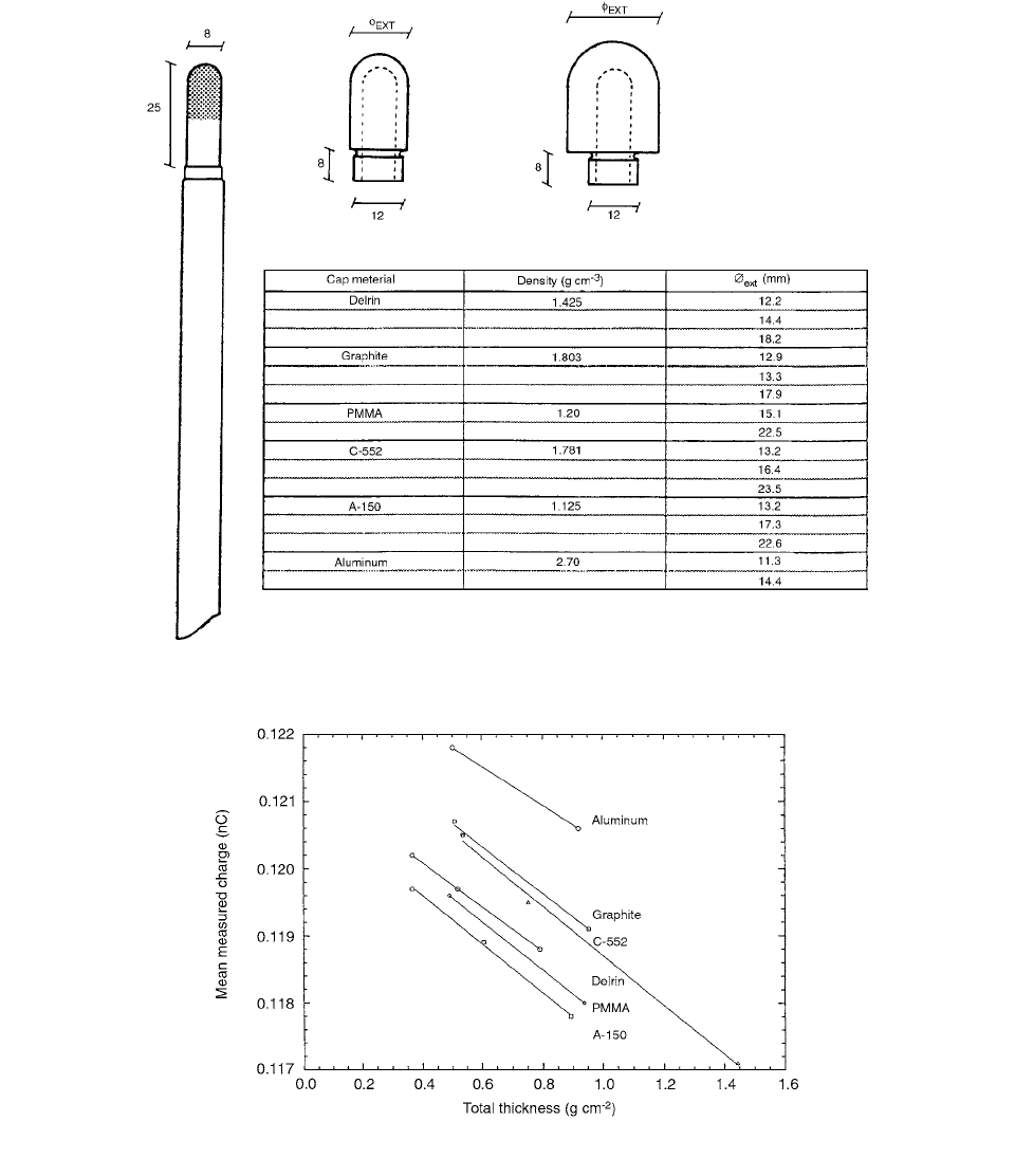
Caps with different thicknesses were made of Delrin,
PMMA, graphite, C-552 (air-equivalent plastic), A-150
(tissue-equivalent plastic), and aluminum (see inset in
Figure 3.28).
The mean measured charge was plotted as a function
of the total thickness (wall and build-up cap) for each
material. The results are presented in Figure 3.29. The k
att
values were obtained by extrapolating the plots of Figure
3.29 to zero wall thickness and correcting for the center
of electron production (CEP). This correction was done
by taking into account the overestimation of the beam
attenuation of the zero-wall correction.
The CEP was determined to be 105 cm of air for
60
Co,
corresponding to 0.136 g cm
2
. Assuming that the cap
materials and air are nearly alike, and taking the experi-
mental values of the slope, the correction for the CEP can
be obtained from the expression
. (3.60)
FIGURE 3.27 Head-scatter measurements for a Philips SL15/MLC, 6 MV. (From Reference [29]. With permission.)
N
gas
N
X
kW/e()
gas
A
ion
A
wall
K
humid
1
L/
()
wall, gas
en
/
()
air, wall
1
()L/
()
cap, gas
en
/
()
air, cap
[]
--------------------------------------------------------------------------------------------------------------------------------------------------------------
N
D
N
X
We()k
as
k
m
k
s
()
c
k
st
()
c
IAEA: N
D
N
X
We()k
att
k
m
k
m
s
air, wall
en
/
()
wall, air
1
()s
air, cap
en
/
()
cap, air
k
att
k
as
A
wall
k
att
1
t
1 slope()CEP()
Ch-03.fm(part 1) Page 114 Friday, November 10, 2000 11:58 AM
Ionization Chamber Dosimetry 115
The mean value of k
att
for a total thickness of 0.5 g
cm
2
was 0.9894 0.0004, independent of the build-up
cap material for the low-density materials used in this
experiment. [32]
The values of k
m
(normalized to the original cap mate-
rial, Delrin) were obtained by the following equation:
(3.61)
where R(t) is the measured charge corrected to reference
conditions for a particular value of the wall thickness t.
Values of k
m
given by AAPM (1983) and SEFM and
CAEA (1987) are given in Table 3.10.
From Figure 3.30 one can verify that the theoretical
values of k
m
are correlated with the mean excitation energy
(I), which is the only material-dependent term in the expres-
sion used for the calculation of k
m
. The variation of k
m
as a
FIGURE 3.28 Drawing of the chamber and build-up caps. All the dimensions are in mm. (From Reference [32]. With permission.)
FIGURE 3.29 Mean measured charge as a function of the total thickness for each material. (From Reference [32]. With permission.)
k
m
Rt
()k
att
t()[]
m
Rt()k
att
t()[]
delrin
Ch-03.fm(part 1) Page 115 Friday, November 10, 2000 11:58 AM
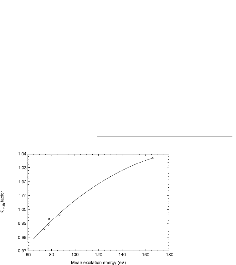
116 Radiation Dosimetry: Instrumentation and Methods
function of I is only 1.7% for the low-Z materi-als com-
monly used in ion chambers but differ by more than 4%
for aluminum compared with graphite, for example. [32]
Perturbation effects are caused in the ionization cham-
ber used in the buildup region because no charged particle
equilibrium exists there. This is mainly due to electron
fluance through the chamber side wall. More accurate dose
measurements in this region can be done with the extrap-
olation chamber.
It is generally accepted that parallel-plate extrapola-
tion chambers provide the most accurate means of mea-
suring dose at the surface and in the buildup region of
megavoltage photon beams. An assumption is made that
the measurement position is at the inside face of the
entrance window of the chamber. For a parallel-plate
chamber of finite electrode separation, this assumption
is not valid since part of the chamber ionization current
is due to electrons emitted from the adjacent side wall in
an extrapolation chamber; on the other hand, the chamber
signal per unit-collecting volume is determined for differ-
ent electrode separations and extrapolated to zero electrode
separation, thus eliminating the side-wall contribution.
A parallel-plate ion chamber was designed by Rawlinson
et al. [34] to study photon build-up. The study has shown
that the side-wall error is primarily dependent on the ratio
of the electrode separation to the wall diameter, as well as
on the wall density and wall angle. Based on these findings,
the design of a fixed-separation chamber is described
which reads to within about 1% of the correct dose.
A cross section through the special ion chamber con-
structed for the study is shown in Figure 3.31. The col-
lector and guard electrodes were formed from a 2-mm
plate of polymethylmethacrylate (PMMA) coated with a
thin (approximately 100 microns) layer of Aquadag colloi-
dal graphite and mounted on a base of A-150 conducting
plastic. A series of fine concentric grooves of diameters
0.5,1, 2, 4, and 7.5 cm cut into the surface of the PMMA
plate defined the edge between the collector electrode and
guard electrode; changes in the collector diameter could be
made by scribing an insulating gap through the graphite at
one of the circles and by shorting an existing gap. The center
wire of a Belden type 9239 low-noise coaxial cable fixed
in a fine hole through the center of the PMMA plate pro-
vided the electrical connection to the collector. The outer
conductor of this cable was connected to the A-150 base
and through it to the guard electrode. The front window
consisted of 1.6 mg cm
2
of aluminized polyethylene
terephthalate (Mylar) stretched over a circular PMMA
frame of 9.5-cm diameter and held by a PMMA retaining
ring. The frame fitted over an annular PMMA spacer of
density 1.17 g cm
3
which determined both the electrode
separation and the wall diameter of the chamber.
TABLE 3.10
Values of k
m
as Calculated by the Protocols
Cap Material AAPM (1983) SEFM & IAEA (1987)
Delrin 0.982 0.989
Graphite 0.985 0.993
PMMA 0.981 0.986
C-552 0.989 0.996
A-150 0.974 0.979
Aluminum
a
1.029 1.037
Note: The
value was taken as 0.59. The differences in k
m
between
the AAPM, SEFM, and IAEA protocols are mainly due to differ-
ences in stopping-power ratios.
a
Stopping power and: absorption coefficient from Rogers et al.
(1985).
Source: From Reference [32]. With permission.
FIGURE 3.30 Theoretical k
m
values as a function of mean excitation energy. (From Reference [32]. With permission.)
Ch-03.fm(part 1) Page 116 Friday, November 10, 2000 11:58 AM
Ionization Chamber Dosimetry 117
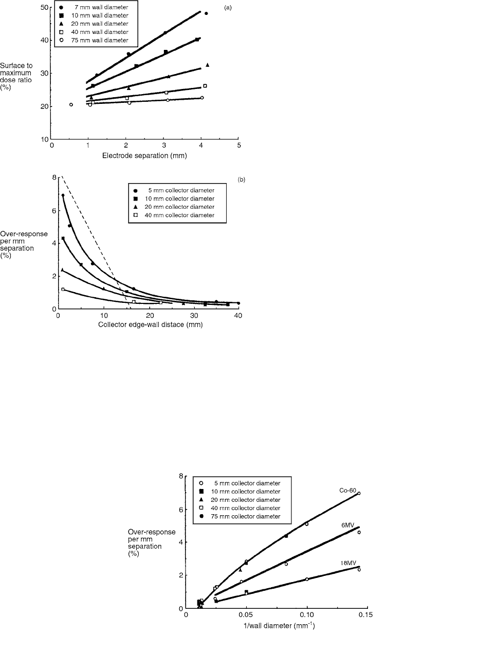
Figures 3.32a and b show the results obtained using
the variable-geometry chamber to measure the surface-to-
maximum dose ratio in the 10 10-cm
2
cobalt beam.
Figure 3a shows, for a chamber of fixed collector diameter,
that the chamber response increases approximately lin-
early with electrode separation and that the rate of increase
depends strongly on the wall diameter (or collector edge-
wall distance).
In Figure 3.32b these slopes and those obtained for
other collector diameters are plotted as a function of col-
lector edge-wall distance. The over-response decreases non-
linearly with collector edge-wall distance, and it also
depends on the collector diameter. Trends similar to those
shown in Figures 3.32a and b are observed at 6 and 18 MV,
though the magnitude of the over-response is smaller at the
higher energies for the same chamber geometry. The surface
dose for a 10 10 cm
2
field was measured to be 13.9
0.5% at 6 MV and 9.7% 0.4% at 18 MV.
The three curves in Figure 3.33 yield chamber over-
responses which are within 1.5% of the original mea-
sured data. The results show that the over-response of a
chamber of given wall diameter is virtually independent
of the relative magnitude of its collector diameter and its
collector-edge wall distance.
A chamber whose wall diameter is 10 mm and elec-
trode separation is 3 mm will, from Figure 3.33, have an
over-response at the surface of a cobalt beam of 15.3%
and therefore a shift, or ‘‘effective window thickness,” of
29 mg/cm
2
(in addition to the actual window thickness of
1.6 mg/cm
2
). This example shows that there is little point
in having a parallel-plate ion chamber for buildup mea-
surements with an ultrathin entrance window if it also has
a large side-wall contribution which will substantially
increase the effective window thickness. [34]
From a least-squares linear fit to the initial part of the
60
Co data of Figure 3.33, a fixed-separation parallel-plate
ion chamber with PMMA walls whose wall diameter is
about 30 times its electrode separation will provide accept-
able accuracy for routine measurements in the buildup
region of beams of
60
Co or greater energy.
The effects of angled walls and low-density walls were
investigated. The results show that when the wall has a
TABLE 3.11
Characteristics of Commercial Chambers
PTW (‘‘Markus”)
Parameter Capintec Model PS-033 Model 30-329
Wall:
Material, density C552,
1.76 g/cm
3
PMMA,
1. 17 g/cm
3
Diameter 17.4 to 23.9 mm 5.7 mm
Angle 65° (approx.) 0°
Collector:
Material C552 Graphited PMMA
Diameter 14.9 mm 5.4 mm
Electrode separation 2.4 mm 2.0 mm
Window:
Material Aluminized Mylar Graphited polyethylene
Thickness 0.5 mg/cm
2
2.7 mg/cm
2
Source: From Reference [34]. With permission.
FIGURE 3.31 Cross section through the variable geometry ion chamber. (From Reference [34]. With permission.)
Ch-03.fm(part 1) Page 117 Friday, November 10, 2000 11:58 AM
118 Radiation Dosimetry: Instrumentation and Methods
positive angulation, the chamber over-response decreases
substantially. [34]
The results of the experiments to determine the effect
of the density of the wall material are summarized in Table
3.12. It can be seen that the density of the wall material
has an important impact on the size of the chamber over-
response. Balsa wood walls, for example, reduce the over-
response to approximately 30% of that expected for
PMMA walls.
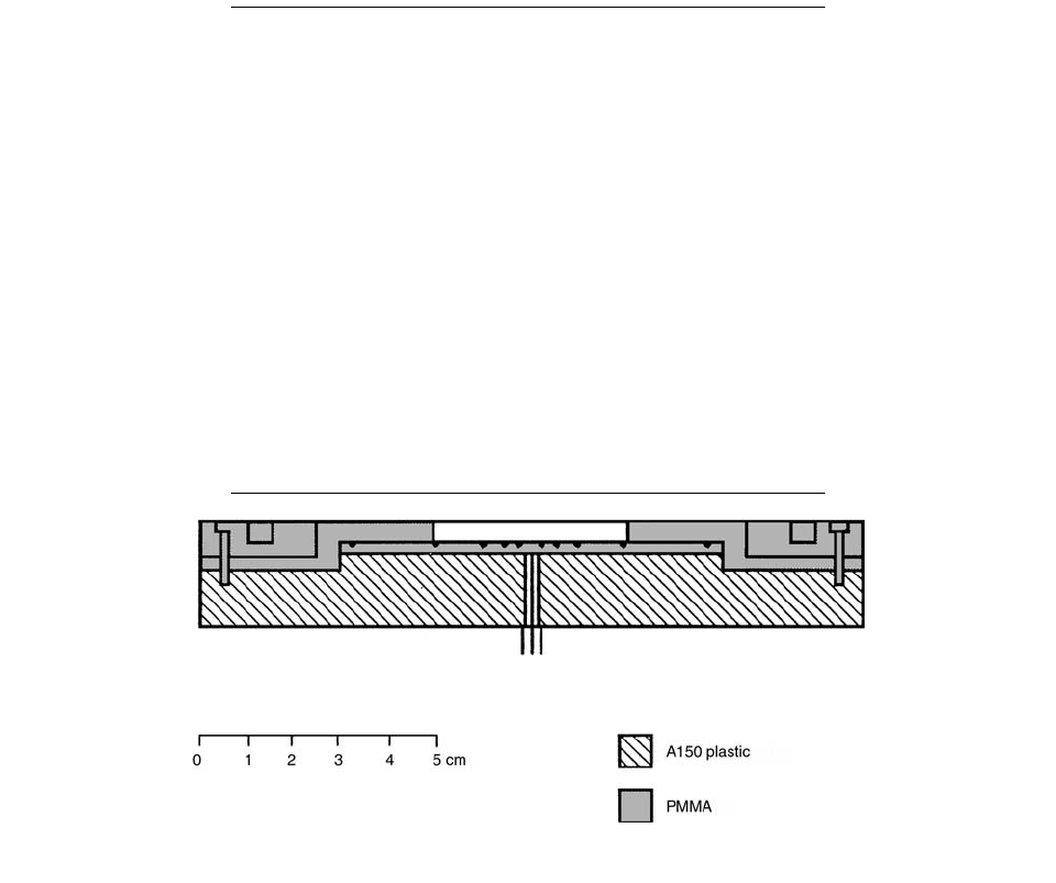
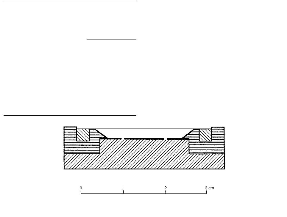
One possible design of a fixed-separation ion chamber
that conforms to the criteria discussed above is shown in
Figure 3.34. The chamber employs sloped PMMA walls of
average diameter 24 mm, an electrode separation of 2 mm,
a collector diameter of 10 mm, and a guard width of 5 mm.
The window diameter is 27 mm. A flange of inner diameter
35 mm projecting 0.5 mm above the entrance plane of the
chamber is employed to protect the window.
Fixed-separation plane-parallel ionization chambers
have been shown by Gerbi and Khan [35] to overestimate
the dose in the build-up region of normally incident high-
energy photon beams. These ionization chambers exhibit
an even greater over-response in the build-up region of
obliquely incident photon beams. This over-response at
oblique incidence is greatest at the surface of the phantom
and increases with increasing angle of beam incidence. In
addition, the magnitude of the over-response depends on
field size, beam energy, and chamber construction. This
study showed that plane-parallel ionization chambers can
over-respond by a factor of more than 2.3 at the phantom
surface for obliquely incident high-energy photon fields.
A model 30-360 extrapolation chamber manufactured
by PTW-Freiburg was the standard of comparison for all
measurements, with an electric field strength of 30 V/mm
of plate separation. This polarizing voltage produced a
current within 1% of saturation. For each extrapolation
chamber data point, readings were taken at electrode sep-
arations of 0.5, 1.0, and 2.5 mm at both a positive and
FIGURE 3.32 Results obtained using variable geometry cham-
ber to measure the surface-to-maximum ratios of the 10
10 cm
2
cobalt beam. (a) Surface-to-maximum ratios as a function of
electrode separation for different wall diameters and a collector
diameter of 5 mm. (b) Percent over-response per mm of electrode
separation as a function of collector edge-wall distance for dif-
ferent collector diameters. The dashed line gives the dependence
on collector edge-wall distance. (From Reference [34]. With
permission.)
FIGURE 3.33 Percent over-response per mm of electrode separation as a function of the inverse of the wall diameter for a PMMA-
walled chanber at the surface of 10
10-cm
2
beams of
60
Co, 6 and 18 MV. (From Reference [34]. With permission.)
Ch-03.fm(part 1) Page 118 Friday, November 10, 2000 11:58 AM
Ionization Chamber Dosimetry 119
negative chamber bias. These readings were corrected for
the polarity effect.
Build-up curves in polystyrene for 5 5 and 20
20 cm
2
6-MV x-ray fields angled at 60° and 75° with no
blocking tray in the beam are shown in Figure 3.35. The
%DD values in the graphs are obtained by dividing the ioni-
zation charge collected at the slant depth along the central
ray of the beam by the ionization charge collected with the
same detector at the reference depth of a normally incident
beam. The relative response as a function of depth along
the central axis of the beam for the Memorial chamber and
TLD powder is also shown in Figure 3.35.
The magnitude of the over-response at the phantom
surface for several fixed-separation plane-parallel cham-
bers as a function of beam angulation for a 5 5-cm
2
field is shown in Figure 3.36. Relative response for these
figures is defined as the %DD at the surface for the test
chamber for a beam incident at
° divided by the %DD
for the extrapolation chamber, 0-mm plate separation, at
the surface for a beam incident obliquely at the same
angle. The response of the chambers at 0°, 30°, 45°, 60°,
and 75° relative to the response of the extrapolation
chamber is shown in Figure 3.36a for 6-MV x-rays. Based
on this data, the relative response of the chambers at 0°
ranged from 1.6 to as high as 2.3 times greater than the
response of the extrapolation chamber. The amount of
over-response increases gradually with increasing angle,
reaching a maximum at about 45°. At beam angles
greater than 45°, the amount of chamber over-response
begins to decline. At a beam angulation of 75°—the high-
est angle of oblique incidence investigated—the chamber
over-response ranges from 1.4 to 1.8. In comparison to
other chambers, the Attix chamber shows a relatively
small amount of over-response at 0°—a factor of about
1.12—with little variation up to a beam angulation of
75°. Angular chamber response at the surface for 24-MV
x-rays is shown in Figure 3.36b. Three of the chambers
show approximately a 1.25 over-response at 0°, while
the Markus chamber over-responds by a factor of approx-
imately 1.4. This over-response increases dramatically
with beam angulation, reaching a maximum between 1.7
and 1.95 at 60°. From 60° to 75°, chamber response
declines for the Markus and the Memorial (circular)
chamber but remains constant for the Capintec and the
Memorial (rectangular) chamber. By comparison, the
Attix chamber shows an over-response of about 1.05 at
0°, with a maximum over-response of 1.2 at 75°.
Again, the amount of over-response of the Attix chamber
is very similar to that exhibited by the extrapolation
chamber with a 2.5-mm plate separation. [35]
From the data shown, electron fluence across a plane-
parallel ionization chamber is disrupted less when the
chamber separation is small, and when the active volume
is isolated from the in-scattering effects of the side walls
of the chamber. This is not only true when high-energy
photons are normally incident upon the chamber, but also
when these beams are obliquely incident upon the chamber.
IV. CHARGE COLLECTION, ION
RECOMBINATION, AND SATURATION
The output current, i, from an ionization chamber is reduc-
ed from the saturation current, i
s
, by initial recombination,
back-diffusion to electrodes, and volume recombination.
TABLE 3.12
Effect of Density of Chamber Walls (
60
Co; 10
10-cm
2
field at 80 cm; 5-mm-diameter collector)
Electrode
Separation
(mm)
Over-response
Wall
Density
Wall
Diameter
(mm)
For
Indicated
density
For
Density
1.17
0.22 12 3.5 5.8% 17.0%
0.22 22 4.1 3.7% 10.3%
0.22 12 2.0 2.2% 9.7%
0.22 22 2.0 1.3% 5.0%
2.15 12 3.1 26.5% 15.1%
2.15 22 3.1 14.0% 7.8%
Source: From Reference [34]. With permission.
FIGURE 3.34 A suggested design of a fixed-separation parallel-plate ion chamber giving acceptably small side-wall error. (From
Reference [34]. With permission.)
Ch-03.fm(part 1) Page 119 Friday, November 10, 2000 11:58 AM