Shani G. Radiation Dosimetry: Instrumentation and Methods
Подождите немного. Документ загружается.

140 Radiation Dosimetry: Instrumentation and Methods
ionization current of a dielectric liquid and the applied
electric field strength for constant dose rate. For low elec-
tric field strengths, the ionization current is reduced from
the linear relation because of general recombination ion
loss.
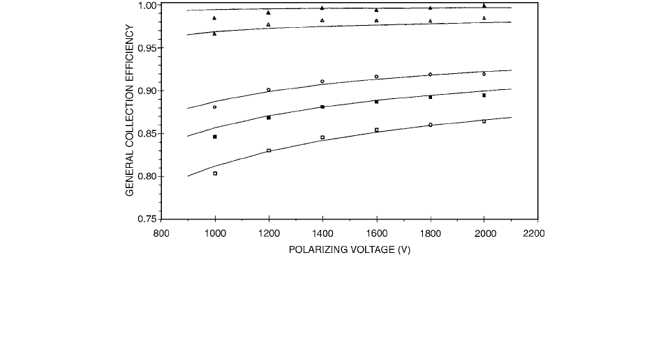
The theoretical and experimental general collection
efficiencies are shown as a function of the polarizing volt-
age for different pulse doses in Figure 3.53 for isooctane
and tetramethylsilane, respectively. The differences
between the theoretical and experimental general collec-
tion efficiencies of the two liquids were within l% for
general collection efficiencies down to 80% for isooctane
and 75% for tetramethylsilane, respectively, using the per-
mittivity of each of the liquids and electric field strengths
exceeding 10
6
V m
1
. The maximum difference between
the theoretical and experimental general collection efficien-
cies occurs for the lowest electric field strengths, 1000 V for
isooctane and 500 V for tetramethylsilane, and for the
highest pulse doses used in the experiments, 1.9 mGy per
pulse. For isooctane, the maximum difference was less
than 1%, and for tetramethylsilane the maximum differ-
ence was about 3%.
V. DETECTOR WALL EFFECT
Plane-parallel ionization chambers are recommended for
the dosimetry of electron beams with mean energies below
about 10 MeV. It is recommended to calibrate plane-
parallel ionization chambers relative to a reference cylin-
drical ionization chamber in a phantom irradiated by a
high-energy electron beam.
Because commercial plane-parallel chambers are not
homogeneous in composition, calculations of k
att
, and par-
ticularly k
m
, will have large uncertainties.
The experimental method applied for the determina-
tion of (
k
att
k
m
) consists of comparing the reading of a
plane-parallel chamber with that of a reference cylindrical
chamber both in air in a
60
Co gamma-ray beam and in a
phantom irradiated by a high-energy electron beam. The
wall correction factor for a plane-parallel ionization cham-
ber was measured by Wittkämper et al. [57]
For a plane-parallel chamber, it can be shown that
(3.114)
where the subscripts
cyl and pp refer to the cylindrical
and plane-parallel chamber, respectively. It is assumed that
p
wall
and p
cel
are unity in the electron beam.
By performing measurements in a photon beam with
the same chambers as used in the high-energy electron
beam, values for
p
wall
can be obtained from a similar
equation: [57]
(3.115)
where subscripts
X and e refer to the photon beam and
the high-energy electron beam, respectively. By position-
ing both chambers with their effective point of measure-
ment at the same depth, the displacement correction will
be unity.
The results of the (k
att
k
m
) determinations of the four
NACP chambers and four PTW/Markus chambers are
summarized in Table 3.14.
FIGURE 3.53 The experimental and theoretical general collection efficiencies for isooctane, with a liquid-layer thickness of 1 mm,
as a function of applied polarizing voltage for different pulse doses. Experimental general collection efficiency at 1.9 mGy per pulse
(
); 1.4 mGy per pulse (); 0.65 mGy per pulse (); 0.27 mGy per pulse (); and 0.06 mGy per pulse (). The theoretical general
collection efficiency is represented by a solid line for each pulse dose. (From Reference [54]. With permission.)
k
att
k
m
()
pp
k
att
k
m
k
cal
()
cyl
M
cyl
M
pp
()
N
k
()
cyl
N
k
()
pp
p
f
()
cyl
p
f
()
pp
()
p
wall
()
pp
p
wall
p
cel
()
cyl
M
cyl
M
pp
()
x
M
pp
M
cyl
()
e
p
f
()
pp
p
f
()
cyl
()
Ch-03.fm(part 2) Page 140 Friday, November 10, 2000 11:59 AM

Ionization Chamber Dosimetry 141
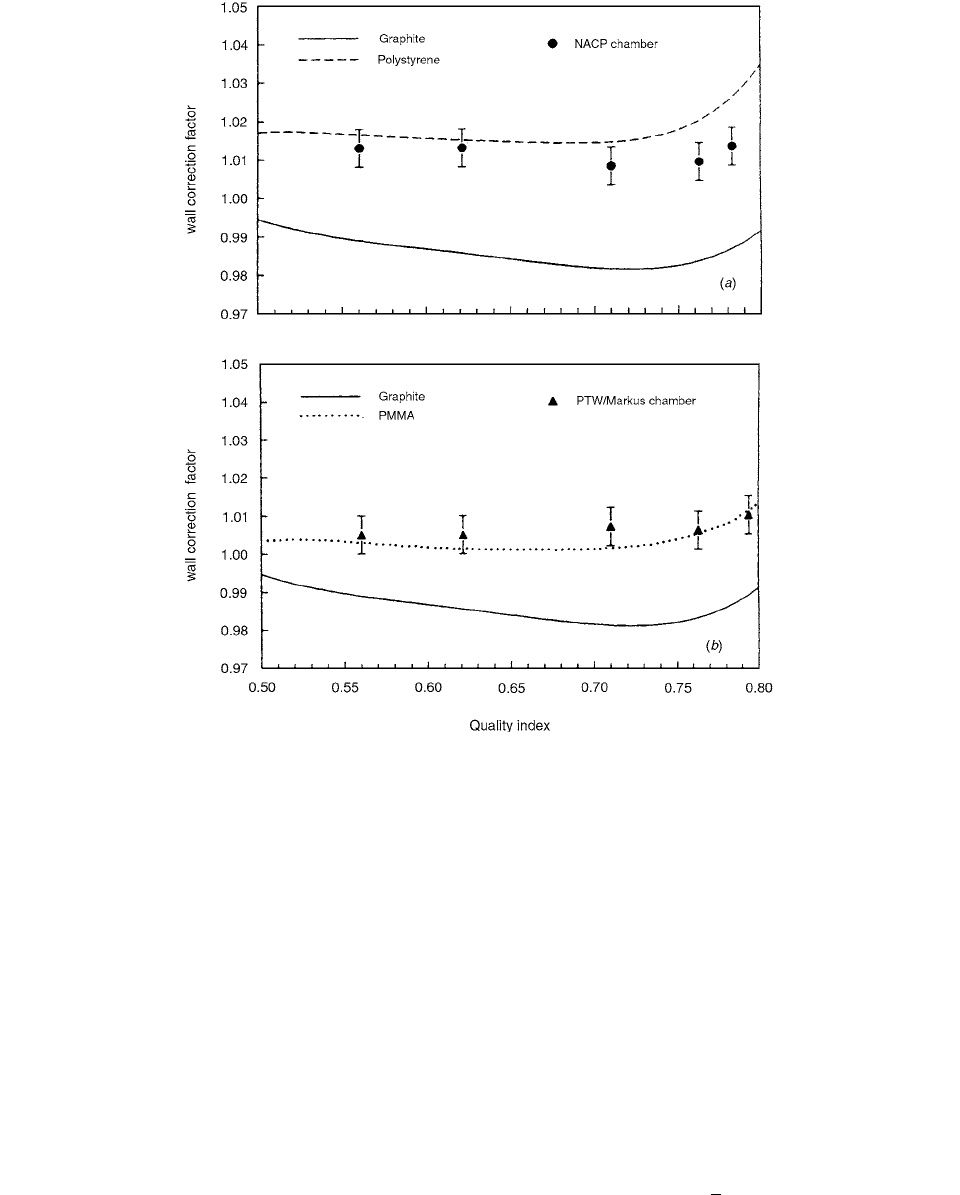
The average results of the p
wall
determinations for the
three type-01 NACP chambers and one PTW/Markus
chamber are summarized in Figure 3.54, presented as a
function of the quality index of the photon beam.
To calibrate a megavoltage therapy beam using an
ionization chamber, it is necessary to know the fraction
of the ionization arising in the chamber wall when this is
made of a material different than the medium. A method
for measuring the ionization fraction produced by elec-
trons arising in the chamber wall (
) was presented by
Kappas et al. [58] The method uses three measurements
at the same point in a medium in order to calculate
.
These measurements are made using the examined cham-
ber with and without a build-up cap and one reference
chamber of wall material equivalent to the medium.
In the AAPM protocol for an absorbed dose in high-
energy photon beams, the general relationship between
the dose to the gas (air) of the chamber and the dose to
the medium that replaces the chamber when it is removed
is given as
(3.116)
where is the ratio of the mean, restricted collision
mass stopping power of the phantom material to that of
the chamber gas and D
gas
is given by the formula
(3.117)
where
M is the electrometer reading, N
gas
is the dose to
the gas to the chamber per electrometer reading, P
ion
is a
factor that corrects for the ionization collection efficiency,
P
repl
is a correction factor for the replacement of the point
of measurement from the geometrical center of the cham-
ber, and P
wall
is a wall correction factor that takes into
account the fact that the chamber wall is usually made of
different material than that of the dosimetry phantom.
P
wall
is equal to unity when the chamber wall and the medium
are of the same composition or in the case of electron
beams. Also, P
wall
is given by a semiempirical expression
(3.118)
when the chamber wall is of a composition different to
the medium. In the above formula,
gives the fraction of
the total ionization produced by electrons arising in the
chamber wall and l
gives the fraction of the total ion-
ization produced by electrons arising in the dosimetry
phantom. is the ratio of the mean mass energy
absorption coefficient for the dosimetry phantom (medi-
um) to that of the chamber wall.
The method used to extract
from the three dose
measurements at the same point is based on the fact that
the absorbed dose in medium, D
med
, is independent of the
measuring device (i.e., chamber). In particular, the dose
D
med
given by each chamber is as follows:
(3.119)
(3.120)
(3.121)
TABLE 3.14
(k
att
k
m
) Values of Different NACP and PTW/Markus Ionization
Chambers
Ionization
chamber Type Serial Number (k
att
k
m
)
NACP 01 06–02 0.978
01 10–01 0.982
01 10–02 0.980
02 12–09 0.978
Dosetek 01 08–09 0.984
weighted average 0.980
PTW/Markus M23343 212 0.993
373 0.992
421 0.996
923 0.992
weighted average 0.993
Source: From Reference [57]. With permission.
D
med
L
---
gas
med
D
gas
L
()
gas
med
D
gas
MN
gas
P
ion
P
repl
P
wall
P
wall
L
---
med
wall
en
-------
wall
med
1
()
en
()
wall
med
D
med
Mw()N
gas
w()
L
---
gas
med
P
ion
P
repl
w()
L
---
med
wall
en
-------
wall
med
1
()
D
med
Mw()N
gas
w()
L
---
gas
med
P
ion
P
repl
w()
L
---
med
wall
en
-------
wall
med
D
med
Mm()N
gas
m()
L
---
gas
med
P
ion
P
repl
m()
Ch-03.fm(part 2) Page 141 Friday, November 10, 2000 11:59 AM
142 Radiation Dosimetry: Instrumentation and Methods
where W is the chamber wall composition,
unknown w
as w with build-up cap,
1 and m is the chamber wall
material equivalent to the medium,
0.
Factors
N
gas
and P
repl
are dependent on the individual
chamber. Finally,
(3.122)
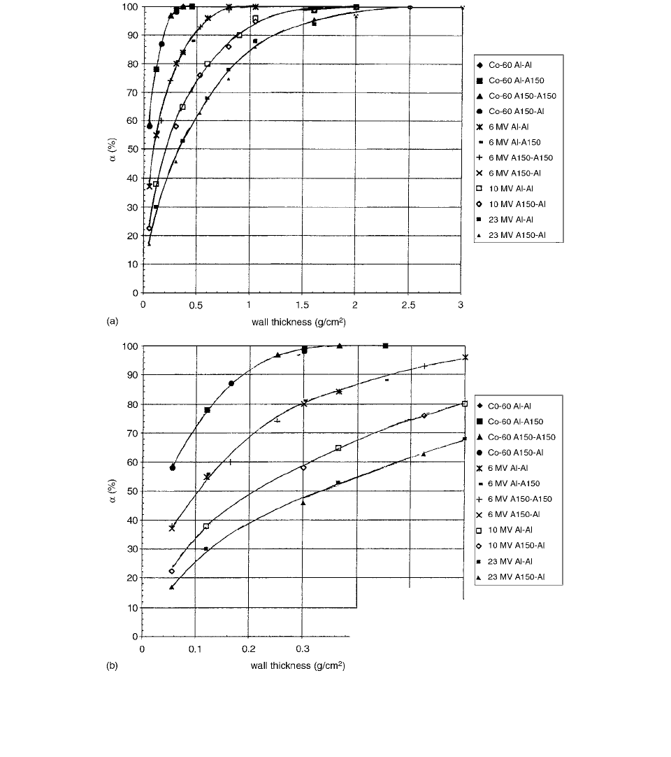
The fraction of ionization due to the wall (
) is inde-
pendent of the wall material, even if it is aluminum. This
is very well demonstrated in Figures 3.55a and b, where
all four combinations of wall cap give results for
,
depending only on the beam energy and wall thickness
and not on the wall material.
Wall attenuation and scatter corrections for ion
chambers were measured and calculated by Rogers and
Bielajew. [59] Using the EGS4 system shows that Monte
Carlo–calculated A
wall
factors predict relative variations in
detector response with wall thickness which agree with
all available experimental data within a statistical uncer-
tainty of less than 0.1%. Calculated correction factors for
use in exposure and air-kerma standards are different by
up to 1% from those obtained by extrapolating these same
measurements.
The measured ionization from a chamber with wall
thickness
t is proportional to R(t), the absorbed dose to
the gas in the cavity. For walls that are thick enough to
establish charged particle equilibrium in the chamber’s
cavity, and assuming the normal tenets of cavity theory
hold, one has
(3.123)
where K
col,air
is the collision kerma in air at the geometric
center of the cavity in the absence of the chamber, s
air,wall
is the stopping-power ratio, is the ratio of spec-
trum-averaged mass-energy absorption coefficients in the
FIGURE 3.54 The wall correction factor, p
wall
, for (a) the NACP chamber and (b) the PTW/Markus chamber in water, as a function
of the quality index of the photon beam. Also indicated are
p
wall
values calculated for a homogeneous PMMA, polystyrene, or graphite
chamber. (From Reference [57]. With permission.)
1 Mm()Mw()
1 Mm()Mw()
---------------------------------------------
Rt() K
col,air
s
air,wall
en
()
air
wall
A
wall
t()A
oth
en
()
air
wall
Ch-03.fm(part 2) Page 142 Friday, November 10, 2000 11:59 AM
Ionization Chamber Dosimetry 143
wall to those in the air, A
wall
(t) is the wall attenuation
correction factor for the particular wall thickness, t, and
A
oth
groups several other small correction factors which
are taken as independent of the wall thickness (stem, elec-
trode, and field non-uniformity effects).
Since A
wall
corrects for both attenuation (which
decreases the response) and scattering (which increases
the response), it can be either greater or less than unity.
However, attenuation usually dominates so that A
wall
is less
than unity.
The value of A
wall
is determined by scoring
(3.124)
where
(3.125)
(3.126)
FIGURES 3.55 (a) A graph representing the fraction of ionization due to the wall (
) vs. the wall thickness for beam energies of
60
Co, 6, 10, and 23 MV and for combinations of wall-cap material Al-Al, Al-A150, A150-A150, and A150-Al, respectively. (The
line is fit by eye to the data.) (b) The same graph as in (a) but for an expanded wall-thickness scale between 0 and 1 g/cm
2
. (The
line is fit by eye to the data.) (From Reference [58]. With permission.)
A
wall
A
sc
A
at
A
sc
r
i
0
r
i
1
()r
i
0
i
1
i
A
at
r
i
0
() r
i
0
e
d
i
i
1
i
Ch-03.fm(part 2) Page 143 Friday, November 10, 2000 11:59 AM

144 Radiation Dosimetry: Instrumentation and Methods
is the energy deposited by electrons generated by the
ith primary photon interaction, is the energy deposited
by electrons generated from the second- and higher-order
scattered photons that arise from the ith primary photon,
and d
i
is the number of mean free paths in the chamber
to the point of interaction of the ith primary photon.
The AAPM protocol (TG39) includes a cavity replace-
ment factor p
repl
that differs from unity for some chambers
but assumes that the wall perturbation factor, p
wall
, may
be taken as unity. The perturbation of the wall has been
determined by Nilsson et al. [60], using a large plane-
parallel ionization chamber with exchangeable front and
back walls. The results show that in many commercial
chambers there is an energy-dependent p
wall
factor, mainly
due to differences in backscatter from the often thick
chamber body as compared to the phantom material.
Backscatter in common phantom and chamber materials
may differ by as much as 2% at low electron energies.
The front walls are often thin, resulting in negligible per-
turbation, but the 0.5-mm front wall of graphite in the
NACP chamber was found to increase the response by
0.7% in a PMMA phantom.
The BPPC-1 chamber has a negligible polarity effect.
Thus, all measurements were made with the same polarity
using a field strength of 50 V mm
1
. The leakage current
was less than 0.01 pA, which is less than 0.01% of the
ionization current obtained in the measurements.
Plane-parallel chambers commercially available often
have composite backscatter walls with thin electrodes of
a material different from the chamber body. Nilsson et al.
measurements simulating the NACP (Scanditronix
NACP-02) and the Attix chambers (Gammex/RMI
model 449) were made both with and without the com-
posite electrodes in a PMMA phantom. The Roos chamber
(PTW type 34001 or Wellhofer IC40), with walls made
of PMMA, was simulated by just using the BPPC-1 cham-
ber in the phantom, and the ionization obtained with this
combination was used as a reference. The measuring
geometries of the different simulated chambers are indi-
cated in Figure 3.56.
If measurements are not performed in a PMMA phan-
tom, the 1-mm front and back walls of PMMA in the Roos
chamber may have an effect on the response of the cham-
ber. Some measurements were thus performed simulating
the Roos chamber in a phantom of polystyrene and com-
pared to the use of a homogeneous polystyrene chamber
in a polystyrene phantom. The experiments were simu-
lated using the EGS4 Monte Carlo system.
Calculations were performed assuming a monoener-
getic parallel electron beam with an energy equal to the
mean energy at the surface obtained from depth-dose dis-
tributions in water and calculated according to IAEA.
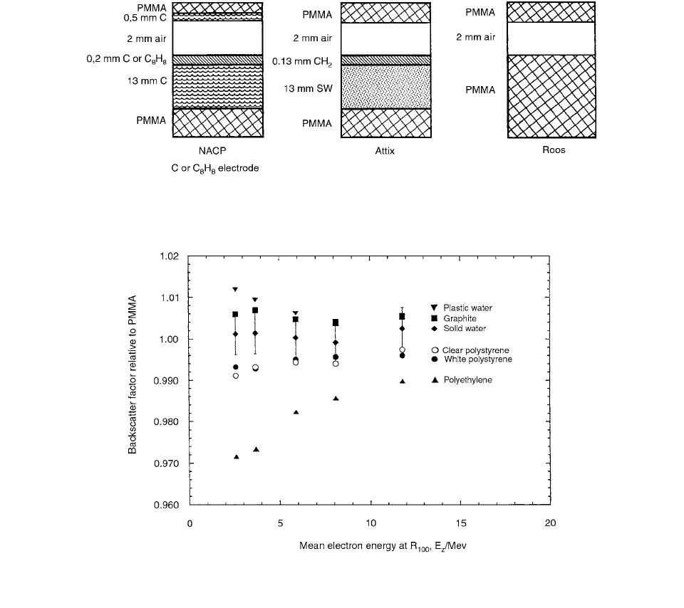
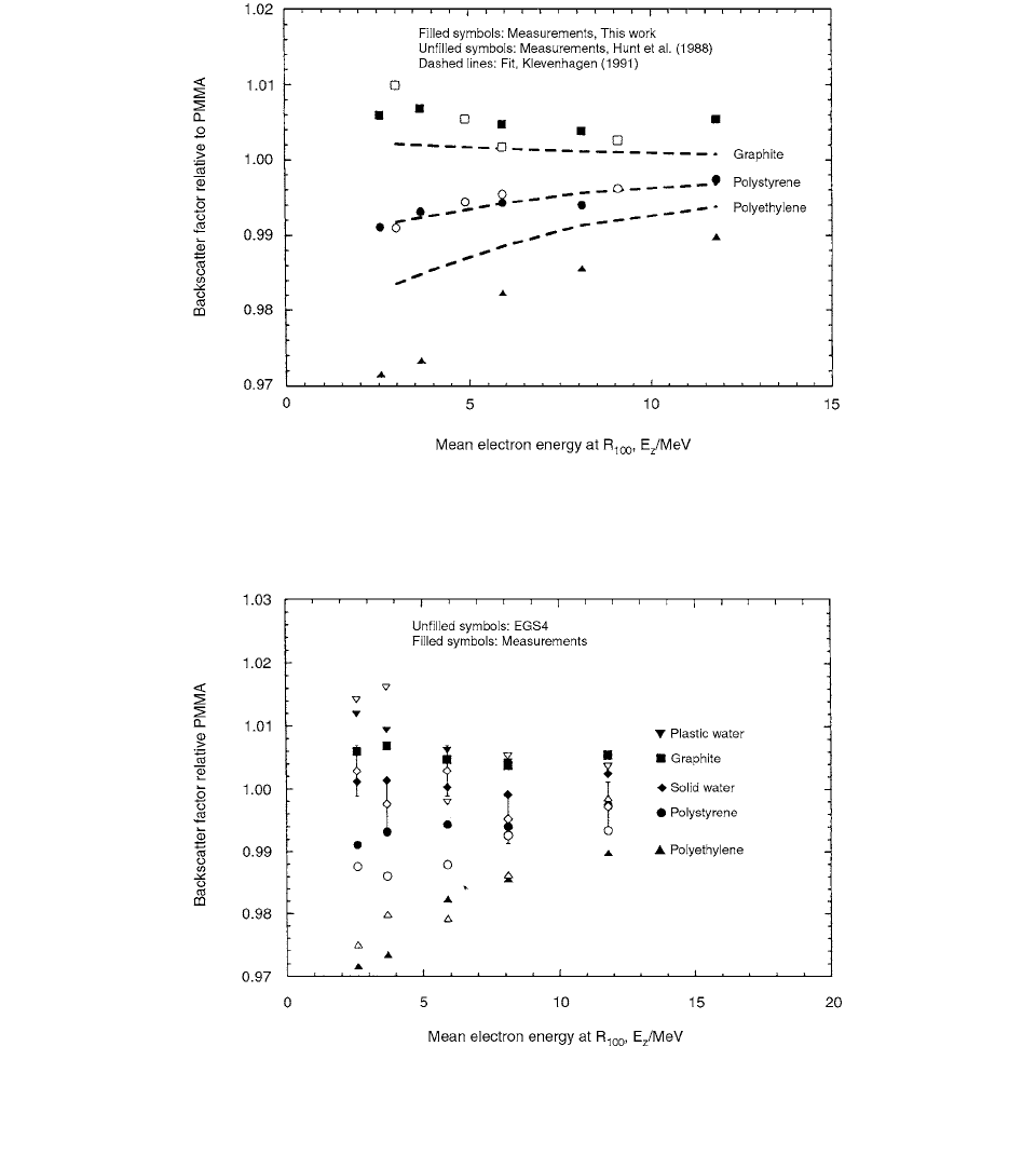
The results of the variation of the backscatter factor
with the mean electron energy at
R
100
are plotted in Figure
3.57. The data are normalized to backscatter from PMMA.
Solid Water appears to be equivalent to PMMA with
respect to backscatter within the experimental uncertain-
ties. Graphite has a backscatter factor about 0.5–0.6%
higher than PMMA, showing a slight increase with
decreasing energy. The backscatter factors of the other
materials show a stronger energy dependence. White and
clear polystyrene have similar backscatter factors, around
TABLE 3.15
Wall Materials Used in the Measurements
Composition
(Z of constituent: fraction
by weight)
Density
(kg m
–3
)
a
Material
Graphite, C C: 1.00 1.69 10
3
Polymethylmethacry-
late, PMMA
(C
5
H
8
0
2
)
n
H:0.0805, C:0.5998, O:0.3196 1.17 10
3
Polyethylene (C
2
H
4
)
n
H:0.1437, C:0.8563 0.95 10
3
Clear polystyrene
(C
8
H
8
)
n
H:0.0774, C:0.9226 1.04 10
3
White polystyrene
(C
8
H
8
)
n
+ TiO
2
1.06 10
3
Solid Water-457
TM
H:0.081, C:0.672, N:0.024,
O:0.199, Cl:0.001,
1.04 10
3
Ca:0.023
Plastic Water
TM
H:0.0926, C:0.6282, N:0.010,
O:0.1794,
1.02 10
3
Cl:0.0096, Ca:0.0795,
Br:0.0003
Source: From Reference [60]. With permission.
r
i
0
r
i
1
Ch-03.fm(part 2) Page 144 Friday, November 10, 2000 11:59 AM
Ionization Chamber Dosimetry 145
1% lower than that of PMMA for low electron energies
at E
z
3 MeV. Polyethylene has a significantly lower back-
scatter factor, which decreases from 0.99 at E
z
12 MeV
to 0.97 at E
z
3 MeV. Plastic Water, on the other hand,
has a 0.5–1% higher backscatter factor as compared to
PMMA and is more graphite-equivalent from this point
of view.
In Figure 3.58 the experimental results for some mate-
rials are compared with the backscatter factors obtained
by Hunt et al. [61], together with data obtained from the
fit proposed by Klevenhagen [114]. The backscatter fac-
tors for polystyrene show very good agreement with the
results obtained in both references, while differences can
be observed for graphite.
Figure 3.59 shows a comparison between the measured
and Monte Carlo values of the electron backscatter coef-
ficient calculated using the EGS4 code. The agreement is
generally within the statistical uncertainties, indicating that
the EGS4 code can be used for relative backscatter deter-
minations in low-atomic-number materials where the
backscatter component is low.
VI. CHAMBER POLARITY EFFECT
The polarity effect is a phenomenon encountered when
using ionization chambers for electron measurements in
which the measured readings vary significantly depending
upon whether the bias applied to the chamber is positive
or negative. TG-25 recommends correcting all ionization
chamber readings if polarity effects greater than 1% are
found. In order to correct for these effects, the readings
must be taken at full positive and full negative bias volt-
ages. In addition, it has been suggested that some ioniza-
tion chambers require an adjustment period of several
minutes in order for the readings to stabilize. The net effect
FIGURE 3.56 The geometries used in the simulation of the NACP, Attix, and Roos plane-parallel chambers. (From Reference [60].
With permission.)
FIGURE 3.57 Backscatter factors relative to PMMA as a function of the mean electron energy, E
z
, at R
100
for different low-atomic-
number materials. (From Reference [60]. With permission.)
Ch-03.fm(part 2) Page 145 Friday, November 10, 2000 11:59 AM
146 Radiation Dosimetry: Instrumentation and Methods
is an approximate doubling of the time required to take
measurements.
Reversing the polarity of the collecting voltage
applied to some flat ionization chambers may change the
value of the readings for photon beams or electron beams.
Consequently, double polarity measurements are recom-
mended for most of the plane-parallel ionization cham-
bers. The average of the absolute value of the charges
collected with a positive and then a negative polarity is
considered close to the true value. This effect is related to
the balance between electrons stopped in or knocked away
from the collecting electrode.
Aget and Rosenwald [62] have recorded the electro-
meter readings
Q
and Q
corresponding, respectively, to
a positive and negative bias voltage. The voltage is applied
to the electrode of the ionization chamber which is not
the collector, i.e., the front window for the plane-parallel
chambers and the external electrode for the cylindrical
FIGURE 3.58 A comparison of backscatter factors for graphite, polystyrene, and polyethylene as a function of the mean electron
energy
E
z
at R
100
obtained in the present measurements (filled symbols), in measurements by Hunt el al. (unfilled symbols), and using
the fit suggested by Klevenhagen (dashed lines). (From Reference [60]. With permission.)
FIGURE 3.59 A comparison of backscatter factors relative to PMMA as a function of the mean electron energy E
z
at R
100
obtained
by measurements (filled symbols) and by EGS4 Monte Carlo calculations (unfilled symbols). (From Reference [60]. With
permission.)
Ch-03.fm(part 2) Page 146 Friday, November 10, 2000 11:59 AM
Ionization Chamber Dosimetry 147
chambers. The Q
Q
ratio is used to estimate the mag-
nitude of the effect obtained in reversing the bias.
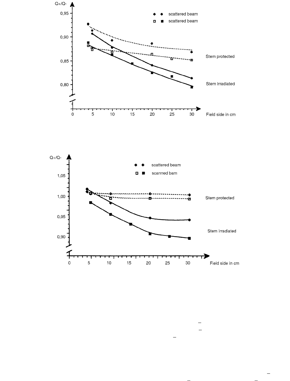
Curves in Figures 3.60 and 3.61 show, respectively,
for the flat and the cylindrical chamber, the variation of
the ratio Q
/Q
vs. the field size. In both figures, it can
be seen that the ratio Q
/Q
is significantly smaller than
1 and that the polarity effect is maximum for larger field
sizes. The effect is slightly larger for the scanned beam
than for the scattering foil beam. In the scanned beam, it
reaches as much as 21% for the flat chamber and 11% for
the cylindrical one. It is about 4% less for the scattering
foil beam. The explanation for the difference between the
two beams is not obvious, but it is likely to be due to the
difference in time structure rather than to the difference
in energy or angular spectrum.
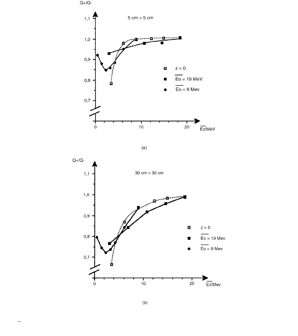
It is clear that the polarity effect is mostly related to
the average energy at the point of measurement. How-
ever, for the same obtained from different combina-
tions of and depths, differences are observed which
indicate that the angular and energy distributions of the
electrons should also be taken into account. The maximum
of the polarity effect has been found at depths where
energy is around 2 MeV (Figure 3.62). This effect is larger
for lower incident energies: Q
Q
0.66 for 3.5
MeV, 0.73 for 9 MeV, and 0.77 for 19 MeV
for the 30 30-cm
2
field.
FIGURE 3.60 Variation of Q
/Q
vs. field size for the flat 0.03-cm
3
chamber. Nominal electron energy is 9 MeV, depth is 2 cm,
and SSD is 100 cm. Continuous lines are for stem and cable irradiated, dashed lines for stem and cable protected. (From Reference
[62]. With permission.)
FIGURE 3.61 Variation of Q
Q
vs. field size for the cylindrical 0.2-cm
3
chamber. Nominal electron energy is 9 MeV, depth is
2 cm, and SSD is 100 cm. Continuous lines are for stem and cable irradiated, dashed lines for stem and cable protected. (From
Reference [62]. With permission.)
E
z
E
z
E
0
E
0
E
0
E
0
Ch-03.fm(part 2) Page 147 Friday, November 10, 2000 11:59 AM
148 Radiation Dosimetry: Instrumentation and Methods
It was found by Havercroft and Klevenhagen [63] that
the NACP, Markus, and Vinten chambers require a cor-
rection on the order of 0.2% in the energy range between
4.5 MeV and 18 MeV. Results have been published in the
past where the polarity effect is on the order of 1%–3%,
increasing to 4.5% in depth or to 20% for small plane-
parallel chambers (Gerbi and Khan). [64] More physical
explanation of the polarity can be found in Reference [65].
A well-constructed chamber should have a polarity
effect not exceeding 1%. If a correction is made for this
effect, the generally accepted approach is to average the
reading taken with the negative (
Q
) and positive (Q
)
polarities, to obtain the mean true ionization charge value
from
(3.127)
FIGURE 3.62 Q
/Q
ratio as a function of E
z
. The continuous line is for surface measurements, changing the nominal incident
energy . The dashed lines are for incident energies of 9 and 19 MeV and different depths. In all cases the 0.03-cm
3
flat chamber
was used in the scattering foil beam. (From Reference [62]. With permission.)
E
0
Q
true
|Q
||Q
|()2
Ch-03.fm(part 2) Page 148 Friday, November 10, 2000 11:59 AM
Ionization Chamber Dosimetry 149
The correction factor for readings taken at negative
bias is given by
(3.128)
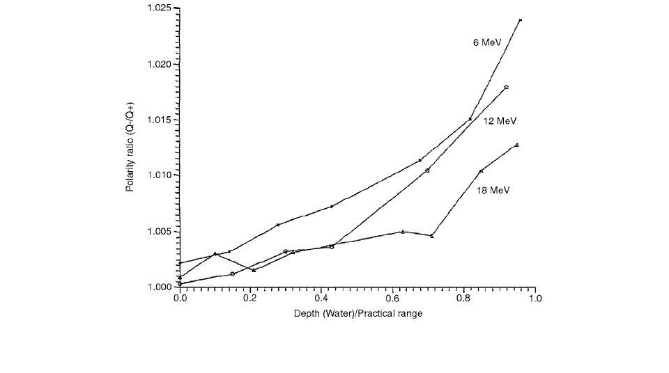
Figure 3.63 shows data for a Calcam chamber obtained in
this study at three different electron energies (6, 12, and
18 MeV) where the energy is, in this case, the incident
(nominal) beam energy at the phantom surface. The ratio
(
Q
/Q
) was calculated for readings taken at increasing
depths from the phantom surface down to approximately
z/R
p
0.9.
The polarity effects of four commercially available ion-
ization chambers were characterized by Williams and
Agarwal [66] and correction factors as a function of mean
energy at depth were tabulated. These included a Farmer-
type chamber, two parallel-plate chambers, and one cylin-
drical chamber used in a scanning water phantom dosimetry
system. Polarity effects were measured at representative
depths along the depth dose curves of 6, 9, 12, 16, and
20 MeV electron beams. The term ‘‘polarity error’’ was
introduced and defined as the error which is present if
polarity effects are ignored. Polarity errors for the four
ionization chambers studied were shown to monotonically
decrease with increasing mean energy at depth and were
largely independent of the energy of the incident electron
beam. Only at very low energies, that is, very near the end
of the practical range, did the correction factors for beams
of different incident energy diverge. Three of the four
chambers studied had correction factors which were inde-
pendent of field size, to within 1/2%. One chamber
showed an increase in correction factor with increasing
field size, which was shown to be mainly due to stem and
cable irradiation.
The polarity error is plotted as a function of mean
energy at depth for the four ionization chambers analyzed
in this study and are shown in Figure 3.64. These data
were fit to the third-order polynomial and the resulting
curve or ‘‘characteristic curves’’ are also shown.
Van Dyk and MacDonald [65] demonstrated that the
polarity effect is due in part to the lack of equilibrium in
the number of electrons entering and leaving the collecting
volume. For monoenergetic electron beams, the net dep-
osition of charge is positive at the surface from the ejection
of secondary charged particles and negative at depth where
the electrons stop in the material. The charge deposition
from electrons stopping in the medium influences the
magnitude of the collecting charge. This, in turn, is depen-
dent on the polarity of the voltage applied to the collecting
electrode. Nilsson and Montelius [67] found that the polar-
ity effect is dependent on sidewall material, chamber
geometry, electron contamination, and the angular distri-
bution of the electron fluence. Gerbi and Khan [64] found
that the polarity effect was small (approximately 1%) up
to a depth of d
max
but increased up to 4.5% at greater depths
near the practical range of the electron beam.
Two plane-parallel ionization chambers (PTW 23343)
and two cylindrical chambers (NEL 2571) were used by
Ramsey et al. [68] to compare the magnitude of the polarity
effect on different types of ionization chambers as well as
individual chambers. The effective volumes of the parallel-
plane chambers and cylindrical chambers were 0.045 cm
3
FIGURE 3.63 Ratio Q
/Q
vs. chamber position in depth of water for the Calcam chamber measured in 6-, 12-, and 18-MeV
(nominal) energy electron beams. (From Reference [63]. With permission.)
f
pol ()
|Q
||Q
|() 2Q
()
Ch-03.fm(part 2) Page 149 Friday, November 10, 2000 11:59 AM