Shani G. Radiation Dosimetry: Instrumentation and Methods
Подождите немного. Документ загружается.

150 Radiation Dosimetry: Instrumentation and Methods
and 0.6 cm
3
, respectively. The N
gas
for each of the chambers
is 4.90 10
8
(PTW 430), 4.75 10
8
(PTW 1663), 4.04
10
7
(NEL 484), and 4.01 10
7
Gy/C (NEL 1626).
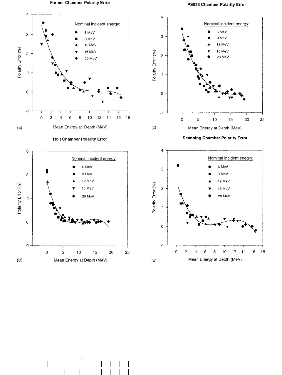
The polarity error is defined as the fractional error
between the reading taken at positive bias and the correct
reading
(3.129)
In order to compare the polarity error for the different
ionization chambers, the measured data was fit using a
non-linear regression of the model
(3.130)
where
P.E. polarity error, E
d
mean energy at depth,
and A, B, C fitting parameters.
This model resulted in a better correlation coefficient
than either a second- or third-order polynomial fit. The
FIGURE 3.64 The polarity error as a function of mean energy at depth (MeV) is shown for the (a) Farmer, (b) Holt, (c) PS-033,
and (d) scanning chambers. The characteristic curve resulting from a third-order polynomial fit to the data is also shown for each
chamber. Data for the first three chambers were taken using a 15
15-cm
2
square field in a polystyrene phantom with 100-cm
source-to-surface distance. Data for the scanning chamber was taken using an identical setup in a water phantom. (From Reference
[66]. With permission.)
polarity error
Q
Q
Q
2
------------------------------
Q
Q
2
------------------------------
-------------------------------------------
Q
Q
Q
Q
-----------------------------
P.E.
1
AB E
d
()
c
------------------------------------
Ch-03.fm(part 2) Page 150 Friday, November 10, 2000 11:59 AM
Ionization Chamber Dosimetry 151
model uses the Levenberg-Marquardt method to combine
the steepest descent method and a Taylor series–based
method for non-linear optimization. Although this model
will approach zero polarity error at large mean energies,
the model adequately fits in the region of lower mean
energies where the polarity error is most pronounced.
VII. DETECTOR PERTURBATION
Two effects perturb the electron fluence compared to that
at the same position in the undisturbed medium. One of
them is due to an imbalance between the number of
electrons that come into the gas cavity through the side
walls and the number of electrons already in the cavity
that leave it. This is due to the fact that the average
angular divergence of the former is greater than that of
the latter. This has become known as in-scattering and
will cause the fluence in the cavity to increase. The other
effect is that the fluence of electrons entering the front
wall of a plane-parallel cavity is hardly affected by the
scattering in the air, whereas in the medium the fluence
continues to build up, owing to scattering. This effect
results in a lower fluence in the gas cavity than in the
medium at the same depth. Thus, the two effects act in
opposite directions. [69]
The second, or fluence build-up, effect is generally
taken care of by referring the reading of the chamber to
an effective point of measurement which differs from that
of the chamber center.
The first effect exceeds 3% for Farmer-type chambers
for below 8 MeV and is one of the principal reasons
why plane-parallel chambers are recommended in low-
energy electron beams.
In coin-shaped gas cavities, the in-scattering perturbation
in the electron fluence is confined to a region close to the
edges of the cavity. Therefore, by constructing the chamber
with a guard ring of sufficient width, it is possible to exclude
the contribution to the ionization signal from this edge region.
Backscatter plays a role in the response of certain
plane-parallel chambers. It should be part of any theoret-
ical treatment of the variation of the overall perturbation
factor
p
Q
with electron energy and with chamber material.
The overall perturbation factor p
Q
will be written as the
product of two factors:
(3.131)
where
p
cav
refers exclusively to the perturbation due to the
air cavity, i.e., predominantly in-scattering effects, and p
wall
refers to any effects due to the composition of the chamber
wall, which could include possible backscatter effects.
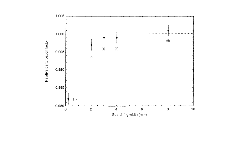
A series of chambers with different guard ring widths,
each with the same cavity height of 2 mm, were compared
to each other in a 6-MeV beam (Figure 3.65). It can be
seen that for widths greater than 3 mm, the chamber per-
turbation remained constant. p
cav
is unity for all guard ring
widths greater than 3 mm.
Values for the fluence perturbation correction factor
were determined by Wittkamper et al. [71], in a number
of electron beams for the commonly applied PTW/Markus
plane-parallel chamber and a cylindrical NE 2571 farmer
chamber. These data were determined relative to the
E
z
p
Q
p
cav
p
wall
FIGURE 3.65 Experimental study of the effect of guard ring width on the perturbation factor for various plane-parallel chamber
designs. The points labelled (1) and (3) are for the PTW/Markus chamber and the NACP chamber, respectively. Points (2), (4), and
(5), represent specially constructed chambers of the PTW/Roos design with guard ring widths of 2, 4, and 8 mm, respectively. The
measurements were made at the depth of dose maximum in a 6-MeV beam against a chamber with an ultrabroad (8-mm) guard ring,
with the normalization of the response quotients obtained in a 20 MeV beam. [70] (From Reference [8]. With permission.)
Ch-03.fm(part 2) Page 151 Friday, November 10, 2000 11:59 AM

152 Radiation Dosimetry: Instrumentation and Methods
NACP plane-parallel chamber as a function of the mean
energy at depth E
z
.
In recent codes of practice the formalism to determine
the absorbed dose in high-energy electron beams is based
on an air kerma calibration of the ionization chamber and
application of the Bragg-Gray equation. This leads to the
following expression:
(3.132)
where D
w
is the absorbed dose to water in the electron
beam at the depth of the effective point of measurement,
M is the instrument reading corrected for temperature,
pressure, recombination, polarity and humidity, N
K
is the
air kerma calibration factor, g is the fraction of the energy
of secondary-charged particles converted to bremsstrahlung
in air at the calibration quality, and k
i
is the product of
correction factors to be applied for the determination of
the absorbed dose to the air in the ionization chamber
cavity from the air kerma in the photon calibration beam
in the absence of the chamber:
(3.133)
s
w,air
is the restricted stopping-power ratio of water to air and
p
i
is the product of correction factors to be applied to the
measurements in the water phantom at the user’s quality:
(3.134)
The wall and central electrode corrections p
wall
and p
cel
are
negligible for cylindrical ionization chambers commonly
applied in electron beam dosimetry. If measurements
are performed using the effective point of measurement,
the displacement correction p
d
can also be omitted, and
the only correction factor in the formalism to be applied
during phantom measurements in electron beams is the
fluence perturbation correction factor p
f
.
For cylindrical chambers p
f
was determined experi-
mentally by Johansson et al. [72] for a number of beam
energies. p
f
is usually given as a function of the mean
electron energy at depth z, .
The plane-parallel chambers are not calibrated in
terms of air kerma in a
60
Co gamma-ray beam but are
calibrated in a high-energy electron beam against a cylin-
drical chamber. In this way, the product
(3.135)
is determined. The fluence perturbation correction factor
of plane-parallel chambers in the calibration electron
beam is thus incorporated in the calibration factor.
By applying Equations (3.132), (3.133), and (3.134)
twice, it follows that
(3.136)
TABLE 3.16
Characteristics of the Reference and Plane-Parallel Ionization Chambers and
Build-Up Caps
NE 2571 NACP PTW/Markus
Chamber Type
Cylindrical
0.6 cm
3
Farmer
Plane-
Parallel
Plane-Parallel
Cavity Length 24 mm Plate
distance
2 mm 2 mm
Dimensions Diameter 6.3 mm Diameter 16.4 mm 6 mm
Chamber wall Material
Thickness
graphite
65 mg cm
–2
Front wall
material
Thickness
Graphite
90 mg cm
–2
Graphited
polyethylene
2.3 mg cm
–2
Side wall
material
Polystyrene Graphited
PMMA
Electrode Material aluminum Material Graphited Graphited
Diameter 1 mm Diameter polystyrene
10 mm
polystyrene
5.4 mm
Build-up cap Material PMMA Material Graphite Graphite
Thickness 558 mg cm
–2
Thickness 540 mg cm
–2
540 mg cm
–2
Guard ring Width 3.2 mm 0.7 mm
NE, Nuclear Enterprises Ltd.; NACP, Scanditronix, Dosetek (Calcam); PTW, Physikalisch Technische
Werkstatte.
Source: From Reference [71]. With permission.
D
w
MN
K
1 g() k
i
s
wair,
p
i
k
i
k
att
k
m
k
cel
k
stem
p
i
p
wall
p
d
p
cel
p
f
E
z
N
K
k
i
p
i
p
f ,x
k
att
k
m
k
cel
()
ref
k
att
k
m
k
cel
()
x
-----------------------------
N
K
()
ref
N
K
()
x
----------------
p
wall
p
d
p
cel
p
f
()
p
wall
p
d
p
cel
()
x
-----------------------------------
Ch-03.fm(part 2) Page 152 Friday, November 10, 2000 11:59 AM
Ionization Chamber Dosimetry 153
where the subscripts x and ref refer to the chamber with
unknown fluence perturbation correction values and to the
reference chamber, respectively.
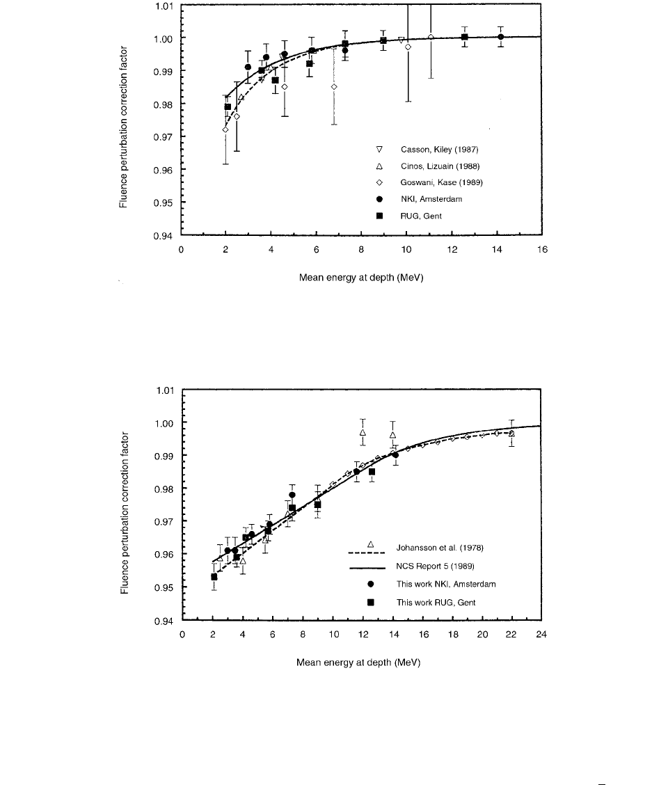
In Figure 3.66 the resulting p
f
values are given for the
PTW/Markus chambers as a function of the mean energy
at the depth of the effective point of measurement, which
is the depth of dose maximum.
In Figure 3.67 p
f
values for the 0.6-cm
3
NE2571 cylin-
drical chambers are given as a function of the mean energy
at depth. In the same figure, the data derived from Johans-
son et al. [72] are depicted as a function of .
The p
f
values reported in this work are obtained by
averaging the results of at least five individual measurement
series. The error bars indicated in Figures 3.66 and 3.67 are
one standard deviation, derived by quadratic summation of
the statistical uncertainties of the ionization chamber read-
ings in the electron beams M
x
and M
ref
and at the air-kerma
calibrations N
k,x
and N
N,ref
. A contribution to the overall
FIGURE 3.66 Fluence perturbation correction values for the PTW/Markus plane-parallel chamber as a function of the mean energy
at depth. The results are normalized to the NACP chambers. The error bars represent one standard deviation. The solid curve represents
a fit through the data points of this work and is adopted in the NCS Code of Practice (1989). The broken curve gives a fit through
all data points in the figure. (From Reference [71]. With permission.)
FIGURE 3.67 Fluence perturbation correction values for the NE2571 cylindrical Farmer-type chamber as a function of the mean
energy at depth. The results are normalized to the NACP chambers. The error bars represent one standard deviation. The solid curve
represents a fit through the data points of this work and is adopted in the NCS Code of Practice (1989). (From Reference [71]. With
permission.)
E
z
Ch-03.fm(part 2) Page 153 Friday, November 10, 2000 11:59 AM

154 Radiation Dosimetry: Instrumentation and Methods
uncertainty of random and systematic errors in the k
i
and
p
i
correction factors of the reference and second chamber
in Equation (3.136) was not taken into account.
The solid curve in Figure 3.66, which is given by
(3.137)
is an exponential fit to the data determined in this work,
weighted with the one standard uncertainty.
A second exponential term was added to make a best
fit to all data given in Figure 3.66. This curve is the broken
curve and is given by
(3.138)
Figure 3.67 shows that for the cylindrical 0.6-cm
3
ionization chamber, good agreement exists between
Wittkämper et al. p
f
values and those determined by
Johansson and colleagues, while Wittkämper et al. [71]
values are computed using the Andreo and Brahme
tables. A partial linear and partial exponential fit was
applied to the data determined in our work, which is
depicted in Figure 3.67 by the solid curve. The analytical
expression of the fit is given by
(3.139)
(3.140)
In electron beam dosimetry, the perturbation effect in
the medium by the ionization chamber cavity is accounted
for by introducing a replacement correction factor, p
repl
.
Another perturbation correction factor, denoted as p
wall
, is
due to the materials of the walls of the parallel-plate cham-
ber differing from the phantom material. Because of the
difficulties in separating these two components, Reft and
Kuchnir [73] measured the overall perturbation factor, p
q
p
repl
p
wall
. A distinct advantage of parallel-plate ionization
chambers over cylindrical chambers is that, p
q
has been
shown to be close to unity at the standard calibration
depth, d
max
.
At the same depth in the phantom, they equate the
percentage depth dose (PDD) measured with the NACP
chamber to that measured with the other chambers, to
derive an equation for the overall perturbation factor:
(3.141)
Therefore,
(3.142)
where is the ratio of the corrected measured
charges at depths d and d
max
, respectively, and
represents the restricted mass collision stop-
ping power ratio of water to air evaluated at depth d
divided by its value at depth d
max
. In this derivation they
have assumed that p
q
is unity for the NACP chamber and
the restricted stopping power ratios cancel because the
measurements are performed at the same depths in the
phantom. For the parallel-plate chambers, p
q
was taken as
1.00 at d
max
with one exception, the Markus chamber. For
this chamber there are experimental data showing that, at
energies below 12 MeV, p
q
measured at d
max
decreases
with decreasing energy.
Using the NACP chamber as the reference detector,
p
q
was obtained for the other three ionization chambers.
The data as summarized in Table 3.18 are obtained by
using Equation (3.142) and show that for the depths
slightly greater than d
ref
, p
q
is unity for the parallel-plate
chambers within the experimental uncertainties.
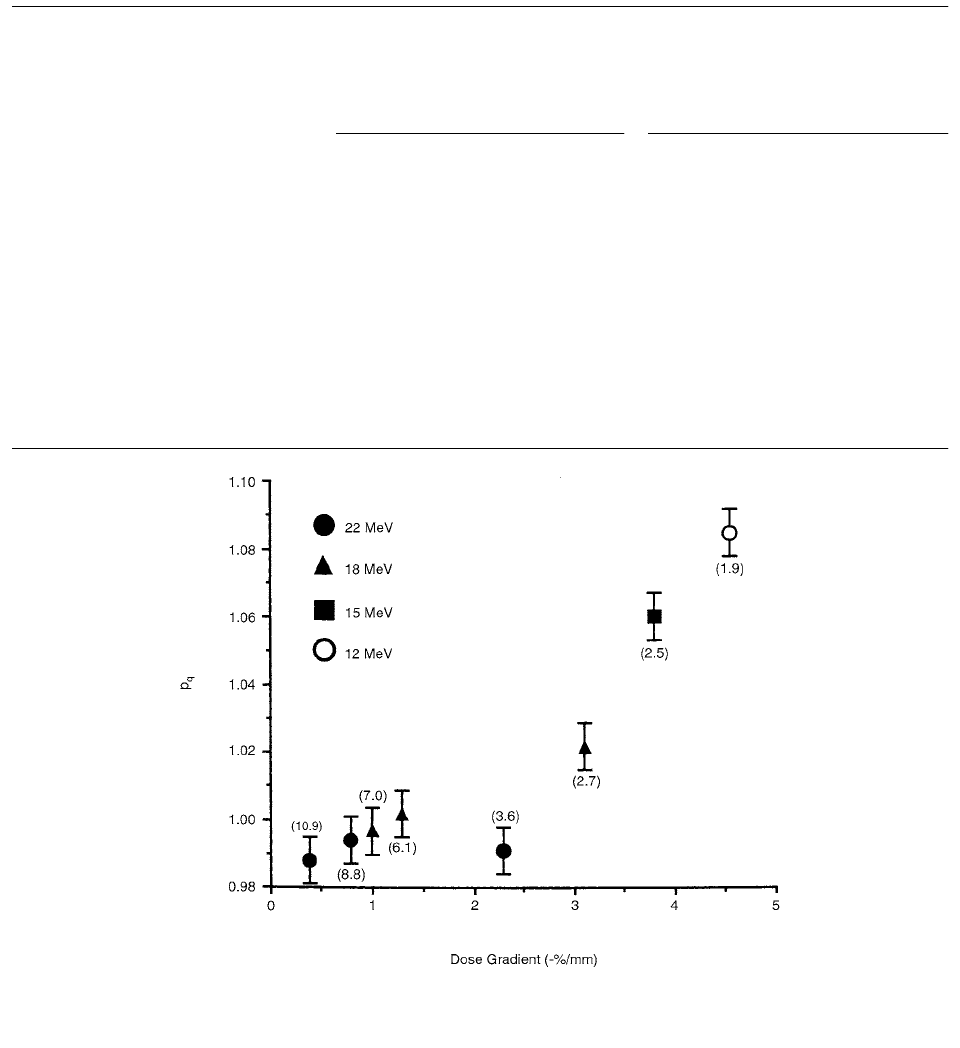
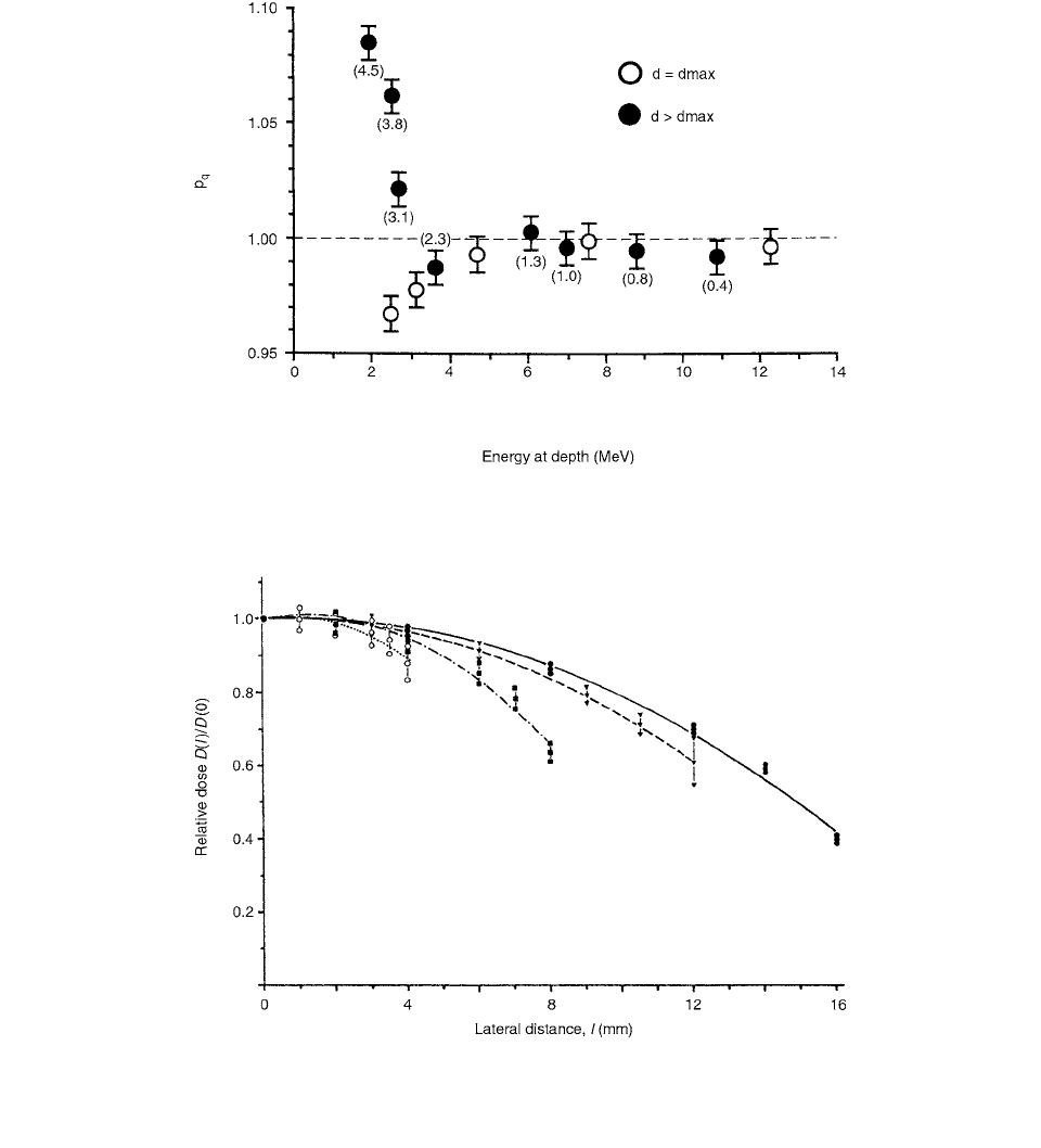
For the Markus chambers, results show that p
q
increases significantly with an increasing dose gradient.
This behavior is illustrated in Figure 3.68. There are a
number of studies showing that this chamber over-responds
(p
q
1.00) at d for low-energy electrons. The results
reported here show that it under-responds (p
q
1.00) in
regions beyond d
max
. The response of the Markus chamber
is reduced in the decreasing portion of the depth ionization
TABLE 3.17
Detector Characteristics
Entrance wall
Type Model Material
Thickness
(g/cm
2
)
Gap
(cm)
Guard
(cm)
Diameter
(cm)
NACP ... Graphite 0.09 0.2 0.3 1.0
ATTIX 449 Kapton 0.0048 0.1 1.35 1.27
MARKUS 30–329 Polyethylene 0.0023 0.2 0.02 0.53
FARMER 30–351 Acrylic 0.059 0.25 ... ...
Source: From Reference [73]. With permission.
p
f
1 0.041e
0.40E
z
p
f
1 0.041e
0.40E
z
0.036e
0.72E
z
E
z
p
f
0.952 0.0028 E
z
for E
z
12 MeV
p
f
1 0.18e
0.21E
z
for E
z
12 MeV
PDD d, E
d
()Q
NACP
L
()
air
H
2
O
[]
d
max
d
Q
ch
L
()
air
H
2
O
p
q
()
ch
[]
d
max
d
p
q
()
d,ch
p
q
()
d
max
,ch
[]Q
NACP
[]
d
max
d
Q
ch
[]
d
max
d
Q[]
d
max
d
L
()
air
H
2
O
[]
d
max
d
Ch-03.fm(part 2) Page 154 Friday, November 10, 2000 11:59 AM
Ionization Chamber Dosimetry 155
curve. This behavior is summarized in Figure 3.69; the dose
gradient is shown in parentheses.
VIII. DISPLACEMENT CORRECTION
For measurements free in air as commonly employed in
calibration situations, the variation in the radiation field
from a point source is governed by the inverse square law.
Inside a phantom, the effective point of measurement can
be displaced relative to the free-in-air condition due to the
replacement of phantom material by the cavity of the
ionization chamber. A correction has to be made for
changes in attenuation and scattering due to this replace-
ment. This can be achieved in terms of a radial displace-
ment using an effective point of measurement or by taking
the geometrical center of the chamber as the measuring
point and applying a displacement correction factor. Such
a factor is essentially the same as the perturbation factor.
Displacement corrections for in-phantom measure-
ments with ionization chambers for the purpose of mam-
TABLE 3.18
Summary of Data Used to obtain p
q
for the Other Ionization Chambers Using Equation (3.142) and the
NACP Chamber as the Reference Detector
E
(MeV)
d
(cm)
Ed
(MeV)
PDD/d
(%/mm)
p
q
NACP Attix Markus Farmer Attix Markus Farmer
22 5.3 10.9 0.4 0.8913 0.8929 0.8993 0.9033 0.998 0.991 0.981 (0.983)
22 6.4 8.8 0.8 0.8150 0.8177 0.8203 0.8326 0.997 0.994 0.973 (0.977)
18 5.3 7.0 1.0 0.8850 0.8834 0.8881 0.8993 1.002 0.996 0.968 (0.972)
18 5.8 6.1 1.3 0.8264 0.8244 0.8251 0.8382 1.002 1.002 0.970 (0.969)
22 9.0 3.6 2.3 0.4184 0.4232 0.4239 0.4350 0.989 0.987 0.956 (0.961)
18 7.6 2.7 3.1 0.4018 0.4075 0.3931 0.4175 0.986 1.022 0.947 (0.958)
15 6.1 2.5 3.8 0.4948 0.4876 0.4660 0.5079 1.015 1.062 0.951 (0.957)
12 4.9 1.9 4.5 0.4796 0.4679 0.4398 … 1.025 1.085
a
…
a
This value was obtained using 0.985 for (P
q
)
d max
from TG 39.
The values in parentheses for the Farmer chamber are taken from Table VIII in the TG-21 protocol.
Source: From Reference [73]. With permission.
FIGURE 3.68 A plot of p
q
vs. the dose gradient for the Markus chamber. The values in parentheses are the energies at depth. (From
Reference [73]. With permission.)
Q[]
d
max
d
Ch-03.fm(part 2) Page 155 Friday, November 10, 2000 11:59 AM
156 Radiation Dosimetry: Instrumentation and Methods
mography are large and represent a major correction to
consider for dose determinations. Experimental data on
displacement corrections depend to a large degree on the
model used to extrapolate to zero cavity radius. Calcula-
tions of displacement correction factors using a Monte
Carlo code for different cavity shapes were carried out by
Zoetelief et al. [74]
For photons employed in mammography, experimental
displacement correction factors obtained by linear extra-
polation to zero cavity radius differ considerably from
unity; e.g., k
d
is about 0.7 for a 0.6-cm
3
Baldwin-Farmer
(Nuclear Enterprises Ltd., UK, type BF2571) ionization
chamber. [75] Non-linear extrapolation to zero cavity
radius for mammography radiation qualities would lead to
different displacement correction factors and their associ-
ated errors. Some of the experimental data at different
cavity radii suggest a nonlinear dependence of the reading
on cavity size. There is, however, a lack of extrapolation
models. In addition, for photons as employed in mammog-
raphy, information is not available for phantom materials
FIGURE 3.69 A plot of p
q
vs. energy at d
max
and at the depth for the Markus chamber. The values in parentheses are the dose
gradients in % per mm. (From Reference [73]. With permission.)
FIGURE 3.70 Lateral dose relative to dose in the center of the cavity for calculations inside spherical cavities of different radii (,
4 mm;
, 8 mm; , 12 mm; and , 16 mm) placed with their geometric centers at 30-mm depth in PMMA phantoms. Fits are
made according to Equation 3.143. (From Reference [74]. With permission.)
Ch-03.fm(part 2) Page 156 Friday, November 10, 2000 11:59 AM
Ionization Chamber Dosimetry 157
other than polymethylmethacrylate (PMMA) and is
restricted to cylindrical and spherical ionization chambers.
There is only limited knowledge of the dependence of
displacement correction factors on depth in phantom. [74]
Calculated dose values at points along the central lat-
eral axis (a line through the center of the cavity parallel
to the x-axis) are given in Figure 3.70 for the spherical
cavities located at 30-mm depth in the PMMA phantom.
A decrease in calculated dose values with increasing lat-
eral distance, l, from the center of the cavity is found.
This is due to an increase in the amount of phantom
material traversed by the photons with increasing lateral
distance from the center of the cavity. Due to partial lack
of side scatter, the calculated dose values at the maximum
lateral distance are still somewhat higher (up to about
10%) than the dose at the same depth in the homogeneous
phantom. Also shown in the figure are fits using STAR-
PAC, a least-squares program for nonlinear functions
[76], according to
(3.143)
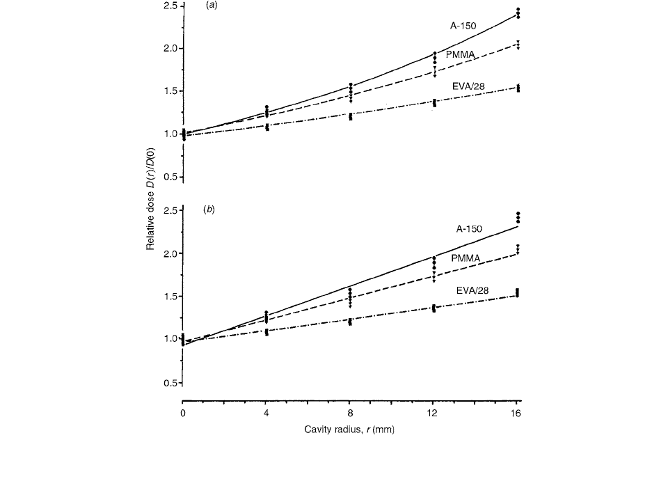
The results of calculations of dose in the cavities rel-
ative to dose at 30-mm depth in the homogeneous phan-
toms, (D(r)/D(0)), for spherical cavities of different radii
placed with their centers at 30-mm depth inside the
PMMA, A-150 plastic, and EVA/28 phantoms are shown
in Figure 3.71 as a function of cavity radius.
It is evident from Figure 3.71 that the exponential fits
are superior.
When parallel-plate chambers are used for dosimetry
in electron fields, the AAPM dosimetry protocol recom-
mends a value of 1.0 for the replacement correction factor,
P
repl,pp,E
, until further data become available. P
repl,pp,E
for
five commercially available parallel-plate chambers was
measured by Reft and Kuchnir [77] as a function of elec-
tron energy from a nominal value of 5.5 to 22 MeV by
comparison with a cylindrical chamber whose P
repl, cyl,E
was obtained from data in the protocol. It was found that
for three of the chambers, P
repl,pp,E
is independent of
energy, consistent with unity within one or two standard
deviations (s.d.). For the fourth chamber, P
repl,pp,E
is sim-
ilarly consistent with one above 10 MeV but decreases at
lower energies, while for the fifth one it shows a system-
atic drop with decreasing energy.
For equal dose to the homogeneous medium at the
effective point of measurement, the following relation
holds:
(3.144)
where
M is the measured charge corrected for temperature,
pressure, polarity effect, and ion collection efficiency. P
repl
and P
wall
are the replacement and wall correction factors,
and pp and cyl refer to the parallel-plate and cylindrical
chambers, respectively. The effect of chamber polarity is
evaluated from the ratio of charges measured with positive
and negative polarizing voltages. For measurements in a
photon field, the AAPM protocol considers P
repl,pp,x
to
equal 1, and when a cylindrical chamber is used at d
max
,
P
repl,cyl,x
1, also. With the exception of the NACP cham-
ber, which has a graphite entrance wall, all measurements
were taken in a phantom matched to the chamber wall
material. Therefore, P
wall
1.0. Equation (3.144) then
reduces to:
(3.145)
where the notation is used to represent the ratio
(M
x
)
cyl
(M
x
)
pp
. For the NACP chamber, was
used; it varied from 0.995 to 0.997 over the energy range
investigated. In the case of the 22-MeV electron beam
irradiation, values of
P
repl,cyl,E
are available only for the
Farmer chamber. The Exradin cylindrical chamber, there-
fore, was not used with the electron beams. Following
recommendations of the AAPM protocol, P
wall
1 for all
chambers and P
repl,pp,E
1 at high electron energies.
Referring to Equation (3.144),
(3.146)
Using Equation (3.144) and (3.145), Reft and Kuchnir
found that for the matched pair of chambers in homoge-
neous media,
(3.147)
where
E and X refer to electron and photon fields, respec-
tively. All of the measurements were made in phantom
with a source-to-surface distance of 100 cm and the effec-
tive point of measurement of each chamber placed at
d
max
.
A 10 10-cm
2
field defined at the phantom surface was
used at nominal electron energies of 5.5, 6, 9, 12, 15, 18,
and 22 MeV from a Cl 2500 linear accelerator.
Results for P
repl
as a function of electron energy for
the five chambers are summarized in Table 3.19.
As seen in Figure 3.72, the experimentally determined
values of P
repl,pp,E
for the Holt, NACP, and Exradin cham-
bers are constant over the energy range investigated. The
respective average values are 0.985, 0.980, and 0.989 with
a standard deviation of 0.5% and an overall uncertainty
of 1% (63% confidence level).
The TG-21 protocol analyzes the replacement correc-
tion factor in two components: (a) gradient correction and
(b) electron fluence correction. The gradient correction,
according to the protocol, arises because, on the descend-
ing portion of a depth-dose curve, the proximal surface of
a cylindrical cavity intercepts an electron fluence that is
f
r
l() 1 dl bl
2
N
gas, pp
M
pp
P
repl, pp
P
wall, pp
N
gas, cyl
M
cyl
P
repl, cyl
P
wall, cyl
N
gas, pp
N
gas, cyl
Mx[]
pp
cyl
M
X
[]
pp
cyl
P
wall
1
N
gas, pp
N
gas, cyl
P
repl, E
[]
pp
cyl
M
E
[]
pp
cyl
P
repl, E
[]
cyl
pp
M
E
[]
pp
cyl
Mx[]
pp
cyl
()P
wall,pp, X
Ch-03.fm(part 2) Page 157 Friday, November 10, 2000 11:59 AM
158 Radiation Dosimetry: Instrumentation and Methods
more intense than that at the measurement depth when the
chamber is removed.
The protocol assumes that P
repl
for photons, under the
calibration conditions, is mainly due to the dose gradient
and that electron fluence corrections are not required since
there is a transient electronic equilibrium at the center of
the chamber. In the case of electron beams, the gradient
correction is ignored as the chamber is positioned at the
depth of maximum dose, but an electron fluence correction
is used as a function of beam energy and cavity diameter.
For the plane-parallel chamber,
P
repl
is assumed to be unity
for both photon- and electron-beam calibration. The pro-
tocol does not address the problem of measuring dose
distributions with ionization chambers that require
replacement corrections. [78]
In an idealized case where a parallel beam of electrons
(or secondary electrons generated by photons) enters the
chamber from a direction perpendicular to the chamber
axis, it has been shown theoretically that the displacement
in the effective point of measurement is given by 0.85r
( 8r/3
). Experimental data show that the actual values
lie between 0 and 0.75r, depending upon beam energy,
in the energy range of medium energy x-rays to 42-MV
x-rays. In the megavoltage range of photon beams, the mea-
surements of Johansson et al. [72] show good agreement
between depth-dose curves measured with plane-parallel
and cylindrical chambers if a constant shift correction of
0.75r is used for the cylindrical chambers.
The TG-21 protocol equates P
repl
or ‘‘gradient correc-
tion” to photon attenuation corrections, calculated by Cun-
ningham and Sontag [79] for cylindrical phantoms of the
same size as the chamber that displaces the medium. These
factors are used to correct for change in energy fluence of
photons at the center of the chamber compared to the
energy fluence that would exist at that point in the absence
of the chamber. Under conditions of transient electronic
equilibrium, the change in photon energy fluence is
equated to the change in electron fluence, which is the basis
of P
repl
corrections.
P
repl
can then be thought of as the ratio of dose to the
medium at the depth of central axis of chamber to that at
the depth of the effective point of measurement.
Mathematically: [78]
(3.148)
FIGURE 3.71 Absorbed dose calculated for spherical cavities with radii of 4, 8, 12, and 16 mm, placed with their geometric centers
at 30-mm depth inside the PMMA phantom, relative to dose in the homogeneous phantom,
D(r)/D(0), as a function of cavity radius.
(a) Exponential fits; (b) linear fits. (From Reference [74]. With permission.)
P
repl
d() Dd()Dd 0.75r()
Ch-03.fm(part 2) Page 158 Friday, November 10, 2000 11:59 AM

Ionization Chamber Dosimetry 159
TABLE 3.19
Summary of Results for P
repl
Nominal
Energy
E
0
(MeV)
E
Z
(MeV)
P
repl,cyl
(TG #21)
Chamber
Type P
repl,pp,E
E-(MeV) E
5.5 4.7 2.5 0.957 N 3.404 1.022 0.978
M 10.34 0.998 0.955
H 0.641 1.032 0.988
C 1.175 1.044 0.999
E 1.027 1.027 0.983
6 5.2 3.1 0.959 N 3.411 1.024 0.982
M 10.42 1.006 0.965
H 0.641 1.032 0.990
C 1.167 1.036 0.994
E 1.024 1.024 0.982
9 8.0 4.7 0.964 N 3.385 1.016 0.979
M 10.56 1.019 0.982
H 0.637 1.026 0.989
C 1.186 1.053 1.015
E 1.027 1.027 0.990
12 11.0 6.4 0.970 N 3.349 1.005 0.975
M 10.49 1.013 0.983
H 0.628 1.011 0.981
C 1.168 1.037 1.006
E 1.021 1.021 0.990
15 14.0 7.6 0.974 N 3.356 1.007 0.981
M 10.49 1.013 0.987
H 0.627 1.010 0.983
C 1.174 1.043 1.016
E 1.018 1.018 0.992
18 17.0 12.3 0.986 N 3.306 0.992 0.978
M 10.30 0.994 0.980
H 0.617 0.994 0.980
C 1.168 1.037 1.022
E 1.001 1.001 0.987
22 20.6 18.4 0.994 N 3.303 0.991 0.985
M 10.31 0.995 0.989
H 0.616 0.992 0.986
C 1.168 1.037 1.031
E 1.005 1.005 0.999
X-MV X
4 … … 1.000 N 3.332 … …
M 10.36 … …
H 0.621 … …
C 1.126 … …
E 1.000 … …
Note: The values for in column 7 were obtained by dividing the electron charge ratio, , by
the photon ratio, , according to Equation (3.147), for
X 4 MV. The last column is the product of values
in columns 4 and 7. N
NACP; M Markus; H Holt; C Capintec; EExradin.
Source: From Reference [77]. With permission.
M[]
pp
cyl
P
repl,E
[]
cyl
pp
P
repl
[]
cyl
pp
M
E
[]
pp
cyl
Mx[]
pp
cyl
Ch-03.fm(part 2) Page 159 Friday, November 10, 2000 11:59 AM