Shani G. Radiation Dosimetry: Instrumentation and Methods
Подождите немного. Документ загружается.

170 Radiation Dosimetry: Instrumentation and Methods
reproduces the data for a water-walled (i.e., wall-less)
chamber with a diameter of 6.4 mm to within 0.25% and
is within 1% of all the IAEA-based data.
Using the protocol of the American Association of
Physicists in Medicine (AAPM) for the determination of
absorbed dose from high energy, the calibration factor
for the PTW M23343 plane-parallel ionization
chamber has been determined by Murali et al. [86] in
60
Co
and high-energy electron beams. Two cylindrical cham-
bers of different wall materials and known values of N
gas
have been used as reference chambers. Results show that
the N
gas
value for the plane-parallel chamber determined
in the
60
Co beam is about 2% higher than the value
obtained in the high-energy electron beams. The discrep-
ancy is attributed to not taking into account a wall-
correction factor for the plane-parallel chamber while cal-
ibrating in the
60
Co beam. is calculated using the
relation
(3.175)
where c represents a cylindrical chamber; p represents a
plane-parallel chamber; M is the meter reading; P
ion
the
correction factor for the ion recombination; is the
fluence correction factor (which depends on the dimen-
sions of the chamber); and is the correction factor
for the non-air equivalence of the wall material. and
for the plane-parallel chamber are assumed to be
unity (AAPM 1983).
The results for the values obtained with
60
Co and
the electron beams are presented in Table 3.24. It is seen
that the value obtained with
60
Co is 2.16% higher
than that obtained with the electron beams. The increase
can be recognized in both sets of measurements.
A set of dosimetric measurements was made by Huq
et al. [87] with Farmer-type PTW and Capintec ionization
chambers in solid water, PMMA, and polystyrene phan-
toms and exposed to a 4-MV photon beam from a Varian
Clinac 4S at Yale, a 10-MV photon beam, 6-and 15-MeV
electron beams, and a 25-MV photon beam. The results
are as follow.
TABLE 3.24
Values
Set I with PTW
(Gy C
–1
)
Set II with NE
(Gy C
–1
)
60
Co 0.4817 0.4812
at d 5 cm (2.16) (2.06)
Electrons (15 MeV) 0.4707 0.4710
d
max
2.2 cm (0.17) (0.11)
Electrons (20 MeV) 0.4721 0.4722
d
max
2.2 cm (0.13) (0.15)
Note: Values in parentheses show the percentage difference of the
value from the mean value (0.4715 Gy C
1
) obtained with the
electron beams.
Source: From Reference [86]. With permission.
N
gas
N
gas
N
gas
N
gas
N
gas
MN
gas
P
ion
P
repl
P
wall
()
C
MP
ion
P
repl
P
wall
()
P
P
repl
p
wall
P
wall
P
repl
N
gas
N
gas
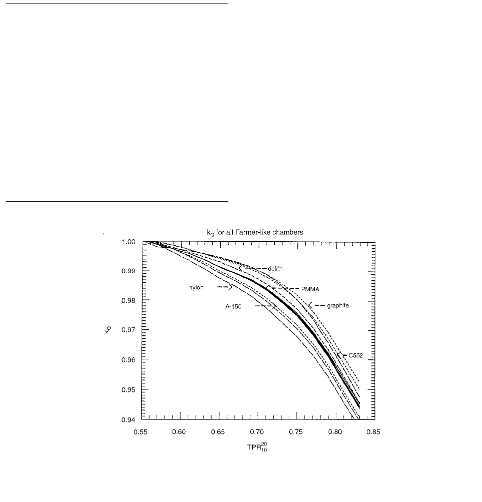
FIGURE 3.79 Calculated factors for all 17 Farmer-like chambers discussed by Rogers. The IAEA data set and AAPM values
of were used in the calculations. Chambers of the same material are shown by the same type of curve. (From Reference [85].
With permission.)
k
Q
P
repl
Ch-03.fm(part 2) Page 170 Friday, November 10, 2000 11:59 AM

Ionization Chamber Dosimetry 171
The ratio of the electrometer readings corrected for
ionization-collection efficiency is equal to the ratio of
percent depth doses at and , i.e.,
(3.176)
where , and M are electrometer readings corrected for
ionization collection efficiency at and d
0
, respec-
tively. d
o
is a reference depth, f is a displacement factor (f
0.5 for electrons and 0.75 for protons), and r is the inner
radius of the chapter. The above ratios for both photons and
electrons were obtained from dosimetry data in clinical use.
The ion chambers used for dose intercomparisons
were all 0.6-cm
3
Farmer-type chambers having different
wall, central electrode, and build-up cap materials.
For electron beams, all measurements were taken with
a source-surface distance (SSD) of 100 cm and a field size
of 10
10 cm at the phantom surface.
The basic equations that are used by both protocols for
the determination of absorbed dose to water are as follows:
1. AAPM protocol
• photons,
(3.177)
• electrons,
(3.178)
2. IAEA protocol
• photons and electrons,
(3.179)
The results of the IAEA absorbed dose to solid water are
compared with those of AAPM in Table 3.25.
Results of absorbed doses to solid water for 6-and 15-
MeV electron beams are given in Table 3.26 for a PTW
chamber. Measurements were performed by using both
chambers in solid water, PMMA, and polystyrene phantoms.
was determined by Reft et al. [88] for six com-
mercially available parallel-plate ionization chambers
using in-phantom and an in-air
60
Co irradiation and an in-
phantom irradiation with a high-energy electron beam. The
chamber characteristics for the six parallel-plate chambers
and three cylindrical chambers are listed in Tables 3.27 and
3.28, respectively. All parallel-plate chambers used were
designed to produce minimal perturbation in the electron
field when placed in a homogeneous medium.
A 22-MeV electron beam with a 1515-cm
2
(0.15
0.15- ) field at a source to surface distance of 1 m was
used for all the electron irradiations. The cylindrical cham-
ber was placed with the axis of symmetry at and
perpendicular to the beam, and the parallel-plate chamber
was positioned perpendicular to the beam axis, with the
center of the inner surface of the front wall at .
For the same exposure in air from the
60
Co beam for
a pair of plane-parallel and cylindrical chambers at the
same point of measurement, one can write
(3.180)
where the measured charge is corrected for temperature,
pressure, polarity effect, and ion-collection efficiency. In
the revised notation of the AAPM protocol by Rogers, and
the letter of clarification by Schulz et al. and are
related by
(3.181)
TABLE 3.25
Absorbed Dose Intercomparisons for 4, 10, and 25-MV Photon Beams in a Solid Water Phantom
Chamber
PTW 0.63 0.988(0.99)
a
0.995 1.000 0.996 0.996(0.99)
Capintec 0.63 0.987(0.99)
a
0.995 0.996 0.994 0.991(0.99)
PTW 0.73 0.992 0.989 1.001 0.998 0.993
Capintec 0.73 0.991 0.989 0.998 0.997 0.990
PTW 0.78 0.995(0.995)
a
0.989 1.001 1.000 0.995(0.99)
Capintec 0.78 0.992(0.99)
a
0.989 0.999 0.997 0.991(0.98)
Average 0.993 0.002(0.994)
Note: has a value of 1.005 for the PTW chamber and 1.006 for the Capintec chamber, and has a value of unity
for both chambers. The 4, 10, and 25-MV data are shown in rows having values equal to 0.63, 0.73, and 0.78, respectively. [87]
a
Values given in parentheses are from theoretical intercomparison in Reference [22] of Chapter 2.
Source: From Reference [87]. With permission.
TPR
10
20
M
u
M
------
s
w,air
()
u
L
()
air
water
----------------------
p
u
P
wall
---------
%DD
P eff
P
P
repl
---------------------
D
w
IAEA
d()
D
w
AAPM
d()
---------------------
N
D
N
gas
P
cel
TPR
10
20
d
o
fr d
o
M
u
M
-------
%DD d
0
f
r
()
%DD d
0
()
--------------------------------------
M
u
d
0
fr
D
water
d
0
() MN
gas
L
()
gas
plastic
P
ion
P
wall
P
repl
en
()
plastic
water
ESC
D
water
d
0
() MN
gas
L
()
gas
plastic
P
ion
P
wall
P
repl
S/
()
plastic
water
plastic
water
D
w
d
0
() M
u
N
D
S
w,air
()
u
P
u
P
cel
h
m
N
gas
m
2
d
max
d
max
M
air,pp,Co
N
xpp,
M
air, cyl, Co
N
xcyl,
N
gas
N
x
N
x
We()N
gas
K
wall
K
comp
K
ion
L
()
air
wall
en
()
wall
air
Ch-03.fm(part 2) Page 171 Friday, November 10, 2000 11:59 AM

172 Radiation Dosimetry: Instrumentation and Methods
for any one chamber, where corrects for the lack of
charged particle equilibrium in the chamber walls,
corrects for ion-collection efficiency, corrects for
any compositional material differences between the cham-
ber wall and build-up cap, is the mean restricted
collision mass stopping power, is the mean mass
energy absorption coefficient, and W/e is the mean energy
expended per unit charge in dry air. Rearranging Equation
(3.181) and using Equation (3.180),
(3.182)
If the product of terms for the parallel-plate
chambers is known, can be obtained from the ratio
of charge measurements and dosimetric quantities given
in TG-21.
The parallel-plate and cylindrical chamber of like
material were positioned in the phantom with their res-
pective points of measurement at a depth of 5.0 g/cm
2
(50 kg/m
2
) and exposed to a
60
Co beam under identical
irradiation conditions. A 10
10-cm
2
field defined at a
source-to-detector distance of 1 m was used for the
exposures.
Results for the determination of using the three
calibration procedures are presented in Table 3.29.
TABLE 3.26
Absorbed Dose Intercomparisons in Electron Beams (PTW Chamber)
Energy
(MeV) Phantom
6 Solid water 0.996 0.998 0.990 1.000 0.997 (0.987)
a
15 Solid water 0.999 0.999 1.000 1.000 1.010 (1.005)
a
6 PMMA 0.993 0.998 0.994 1.000 0.999 (0.989)
a
15 PMMA 0.998 0.999 1.000 1.000 1.010 (1.007)
a
6 Poly 0.993 0.998 0.993 0.977 0.973 (0.965)
a
15 Poly 0.994 1.000 1.000 0.999 1.005 (1.007)
a
Average 0.999 0.014 (0.993 L0.017)
Note: For this chamber has a value of 1.008 and as has a value of 1.005.
a
Values given in parentheses are from the theoretical intercomparison.
Source: From Reference [87]. With permission.
TABLE 3.27
Physical Characteristics of the Parallel-Plate Chambers Used by Reft et al.
Guard
Sensitive air-
volume Entrance Window Buildup Cap
Chamber Width Radius Depth
Thickness
(kg/m
2
)
Radius
(10
–3
m)
Thickness
(kg/m
2
)Type Model (10
–3
m) (10
3
m) Material Material
NACP … 3.0 5.0 2.0 Graphite 0.900 15 4.10 Graphite
Markus 30–329 0.2 2.7 2.0 Polyethylene 0.023 15 5.00 Acrylic
Holt 30–404 5.0 12.5 2.0 Polystyrene 4.200 … … …
(Carbon-coated)
Capintec PS-033 0.5 8.1 2.4 Mylar 0.005 5.00 Polystyrene
(Aluminized)
Exradin P-11 5.1 10.0 2.0 Polystyrene-equiv. 1.180 22.5 4.00 Polystyrene
(Conducting
plastic)
Attix 449 13.5 6.35 1.0 Conductive
Kapton
0.048 30.0 4.95 Solid Water
(RMI)
Source: From Reference [88]. With permission.
S
w,air
()
u
L
()
air
med
S
()
med
water
----------------------------------------------
p
u
P
repl
---------
M
u
M
------
h
m
med
water
-------------
D
w
IAEA
d
0
()
D
w
AAPM
d
0
()
-----------------------
P
cel
N
D
N
gas
K
wall
K
ion
K
comp
L
en
N
gas,pp
We()N
xcyl,
M
air,Co
[]
pp
cyl
L
()
wall
air
en
()
air
wall
[]
pp
K
wall
K
comp
K
ion
[]
pp
K
wall
K
comp
N
gas,pp
N
gas,pp
Ch-03.fm(part 2) Page 172 Friday, November 10, 2000 11:59 AM

Ionization Chamber Dosimetry 173
The question whether results of measurements made
in different phantom materials using different ionization
chambers are consistent with each other was investigated
by Huq et al. [89] Two 0.6-cc Farmer-type chambers, a
PTW N23333, NA 30-351, NA 30-352, and a Capintec
PR 06G chamber were used. They consisted of very dif-
ferent walls, build-up caps, and central electrode materi-
als. The wall and build-up cap material of the PTW cham-
ber was made of PMMA, and the central electrode was
made of aluminum. By contrast, the Capintec chamber
had an air-equivalent wall, polystyrene build-up cap, and
an air-equivalent plastic central electrode.
Absorbed dose at a point in a water phantom was
determined from measurements in a nonwater (or water)
phantom using the following expression:
(3.183)
where is the dose in water at a depth ;
is the dose to the gas in the chamber per unit elec-
trometer reading corrected for temperature, pressure, and
ion collection efficiency; is the ion-chamber
reading corrected for polarity and ion recombination at
the effective depth in the medium; is the
ratio of mean restricted collision stopping powers of med
to air; is the ratio of average unrestricted colli-
sional stopping powers of wat to med; is the differ-
ence in electron fluence between nonwater and water
phantoms at water equivalent depths; and is a
replacement correction that accounts for the change in
photon and electron-beam fluence that occurs because of
the replacement of phantom material by the air cavity.
If measurements are made in a nonwater-equivalent
phantom, then the protocol recommends that the depth in
the nonwater-equivalent phantom be scaled to that of the
water-equivalent phantom by the following expression:
(3.184)
If cylindrical chambers are used for depth-ionization mea-
surements, then replacement corrections are needed
to convert depth-ionization data to depth-dose data.
TABLE 3.28
Physical Characteristics of the Cylindrical Chambers Used by Reft et al.
Inner
Axial length
Entrance Window
Thickness
Build-up cap
Thickness
Chamber
Inner
Radius N
gas
Type Model (10
–2
m) (10
–2
m) Material (kg/m
2
) Material (kg/m
2
) 10
7
Gy/C
Farmer 30–35
a
0.305 2.20 Acrylic 0.59 Acrylic 5.30 4.57
PTW
Farmer N30–351
b
0.304 2.20 Graphite 0.96 Graphite 4.89 4.62
PTW
Farmer 2571
c
0.315 2.25 Graphite 0.65 Graphite 4.89 3.99
NEL
a,b
Farmer-type chamber available from Nuclear Associates, Carle Place, NY 11514.
c
Farmer-type chamber available from Nuclear Enterprises America, Fairfield, NJ 07006.
Source: From Reference [88]. With permission.
TABLE 3.29
Summary of Results for ( 10
7
Gy/C) Using the Three Different Calibration Methods
22E
60
Co (Phantom)
60
Co (Air)
Chamber N
gas,pp
P
wall,pp
N
gas,pp
K
wall
K
comp
N
gas,pp
NACP 2.9900 13.530 3.0176 1.027 13.380 3.0000 1.0250 13.49 13.5 0.1
Markus 10.280 46.700 10.3140 1.000 46.920 1.0340 0.9970 47.25 47.0 0.3
Holt 0.6157 2.797 0.6258 1.000 2.807 0.6199 0.9904 2.821 2.81 0.01
Capintec 1.2120 5.506 1.1719 0.960 5.475 1.1640 0.9579 5.476 5.49 0.02
Exradin 0.9326 4.236 0.9518 1.000 4.269 0.9400 0.9984 4.243 4.25 0.02
Attix 5.1680 23.480 5.2790 1.015 23.640 0.5223 1.0060 23.61 23.6 0.1
Source: From Reference [88]. With permission.
N
gas pp,
M[]
pp
cyl
M[]
pp
cyl
M[]
pp
cyl
N
gas
〈〉
D
wat
d
wat
() N
gas
Q
corr
d
med
()L
()
air
med
S
()
med
wat
med
wat
P
repl
D
wat
d
wat
() d
wat
N
gas
Q
corr
d
med
()
d
med
L
()
air
med
S
()
med
wat
med
wat
P
repl
d
water
d
med
eff
d
med
R
50
wat
R
50
med
----------
P
repl
Ch-03.fm(part 2) Page 173 Friday, November 10, 2000 11:59 AM
174 Radiation Dosimetry: Instrumentation and Methods
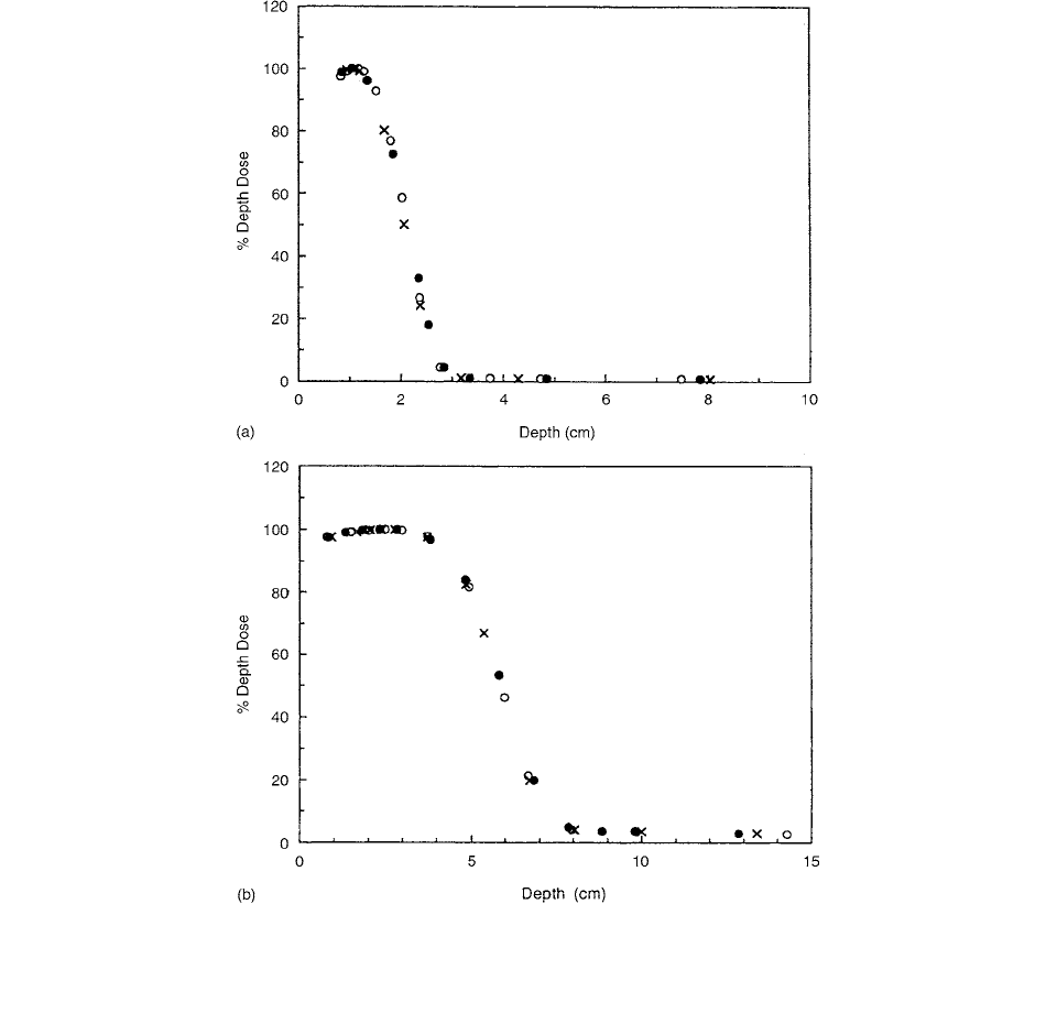
Figure 3.80 shows the relative depth-dose data for 6-
and 15-MeV electron beams generated by using a PTW
chamber in solid water, PMMA, and clear polystyrene
phantoms, using TG-25 except for the bremsstrahlung tail
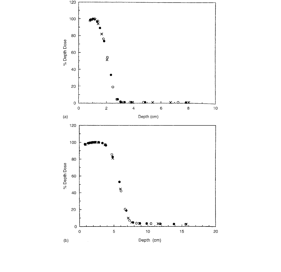
section of the curves. Similar data for the Capintec cham-
ber are given in Figure 3.81. The figures clearly show that
the depth-dose data measured in a solid water phantom
are essentially indistinguishable from those obtained from
measurements made in the PMMA and clear polystyrene
phantoms at both energies. Thus, if one measures depth
ionization in a solid water, PMMA, or clear polystyrene
phantom and follows the recommendations of the TG-25
protocol to convert relative depth ionization to relative
depth dose, then no significant differences will be
observed between the relative depth doses obtained from
measurements made in the solid water, PMMA, and clear
polystyrene phantom.
The AAPM TG-39 protocol has proposed three dif-
ferent methods of calibrating plane-parallel ionization
chambers, i.e., in-phantom irradiation with a high-energy
electron beam and in-phantom and in-air
60
Co irradiation.
To verify the consistency of the three methods, Almond
et al. [90] have measured values using each of these
techniques for the five most commonly used plane-parallel
chambers considered by the protocol. Their results dem-
onstrate that the measured values for the three dif-
ferent methods for any of the chambers agree to within
0.6%.
The five plane-parallel chambers considered by the
AAPM TG-39 protocol were used and designated as
FIGURE 3.80 Central axis relative depth-dose data for 6- and 15-MeV electron beams measured by using a PTW chamber in solid
water, PMMA, and clear polystyrene phantoms; (a) 6-MeV and (b) 15-MeV electron beams. Solid circles are data for solid water;
open circles are for clear polystyrene; and crosses are for PMMA phantom. (From Reference [89]. With permission.)
N
gas
pp
N
gas
pp
Ch-03.fm(part 2) Page 174 Friday, November 10, 2000 11:59 AM
Ionization Chamber Dosimetry 175
“Capintec,” “Exradin,” “Holt,” “NACP,” and “PTW-
Markus.” Their characteristics and individual parameters
are listed in Table 3.30.
The comparisons were made against a PTW graphite
cylindrical Farmer-type chamber, number N30001G, with
an ADCL exposure factor and a cav-
ity-gas calibration factor , which was
calculated by using The
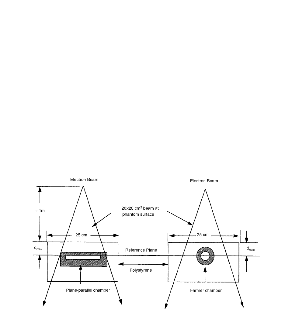
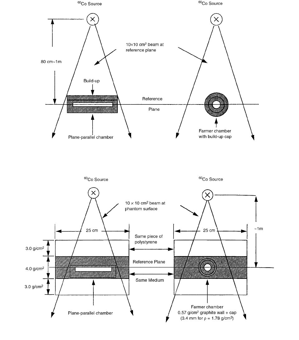
experimental setup is schematically shown in Figure 3.82.
Intercomparison between the plane-parallel chamber
and the PTW Farmer cylindrical chamber was performed
in a
60
Co beam in air using a 10 10-cm
2
(0.10 0.10 m
2
)
field defined at 0.80 m. The experimental setup is shown
in Figure 3.83. Under these conditions, the exposure
calibration factor for the plane-parallel chamber is given
by
(3.185)
where and are, respectively, the meter readings
of the cylindrical and plane-parallel chambers, corrected
for temperature, pressure, and polarity; and ,
are, respectively, the exposure calibration factors for
60
Co
radiation of the cylindrical and plane-parallel chambers.
was then calculated from the ratios of
, given by the AAPM TG-39 protocol.
The intercomparison between the plane-parallel
chamber and the PTW Farmer chamber was performed in
FIGURE 3.81 Central axis relative depth-dose data for 6- and 15-MeV electron beams measured by using a Capintec chamber in
solid water, PMMA, and clear polystyrene phantoms; (a) 6-MeV and (b) 15-MeV electron beams. Solid circles are data for solid
water; open circles are for clear polystyrene; and crosses are for PMMA phantom. (From Reference [89]. With permission.)
N
x
5.455 RnC()
N
gas
cyl
4.653 RnC()
N
gas
cy
N
x
A
ion
()
cyl
8.53 10
3
N
X
pp
N
X
cyl
M
cyl
M
pp
-------------------
M
cyl
M
pp
N
x
cyl
N
x
pp
N
gas
pp
N
gas
pp
N
x
A
ion
()
pp
Ch-03.fm(part 2) Page 175 Friday, November 10, 2000 11:59 AM
176 Radiation Dosimetry: Instrumentation and Methods
a
60
Co beam at a depth of 5 g/cm
2
(50 kg/m
2
) in a phantom
of a material selected to match that of the plane-parallel
chamber as described in the AAPM TG-39 protocol. The
experimental setup is shown in Figure 3.84. Under these
conditions, is given by
(3.186)
where and are, respectively, the meter readings
of the cylindrical and plane-parallel chambers under the
above conditions, corrected for temperature, pressure, and
polarity; is the factor that corrects the ionization
recombination measured by the two-potential method; and
is the correction factor for the replacement of phan-
tom material by the cavity of the cylindrical ionization
chambers. is taken as unity in the AAPM TG-21
protocol for the plane-parallel chambers, so it does not
appear in the above equation. is the correction factor
for the chamber materials being different from that of the
phantom.
TABLE 3.30
Physical Characteristics of Plane-Parallel Ionization Chambers Used by Almond et al.
Chamber
Wall: Material
Thickness
(cm)/(mg/cm
2
)
Collector: Material/
Diameter
(cm)
Guard Ring
Radial Width
(cm)
Electrode
Spacing
(cm)
Nominal
Volume
(cm
3
)
Recommended
Build-Up/Thickness
(cm)/dia.(cm)
Aluminized Conducting air- Conducting air-
Capintec polyethylene equivalent equivalent 0.24 0.5 Polystyrene/
0.001/0.5 plastic 1.6 plastic 0.05 0.48/3.0
Conducting Conducting Conducting,
Exradin Polystyrene polystyrene 2.0 polystyrene 0.5 0.2 0.6 Polystyrene/
0.1/104 0.48/4.5
Polystyrene Graphite Graphite
Holt 0.4/418 polystyrene 2.5 polystyrene 0.5 0.2 1.0 No additional
Graphite and
NACP Mylar 0.5 and Graphite/1.0 Graphite/0.3 0.2 0.16 Graphite/0.3/3.0
0.008/93
Graphite Graphite PMMA Graphite
PTW- Polyethylene 0.54 PMMA 0.07 0.2 0.055 Acrylic/0.42/3.0
Markus 0.0025/2.3
Source: From Reference [90]. With permission.
FIGURE 3.82 Experimental setup for the electron-beam method. (From Reference [90]. With permission.)
N
gas
pp
N
gas
pp
MN
gas
P
ion
P
repl
P
wall
()
cyl
MP
ion
P
wall
()
pp
-------------------------------------------------------
M
cyl
M
pp
P
ion
P
repl
P
repl
P
wall
Ch-03.fm(part 2) Page 176 Friday, November 10, 2000 11:59 AM
Ionization Chamber Dosimetry 177
The values obtained for each chamber by using
three different calibration methods are shown in Table
3.31a. [90]
Calibration of
192
Ir PDR brachytherapy source was per-
formed by Reynaert et al. [91] in a water phantom at short
distances (1.0, 2.5, and 5.0 cm) using an NE2571 Farmer-
type ion chamber. To convert the measured air-kerma rate
in water to dose rate to water, a conversion factor (CF) was
calculated by adapting the medium-energy x-ray dosimetry
protocol for a point-source geometry. The CF was calcu-
lated by Monte Carlo simulations, where the source-ion-
ization chamber geometry was modeled accurately. In a
second method, a combination of Monte Carlo simulations
and measurements of the air-kerma rate in water (at 1.0,
2.5, and 5.0-cm distance) and in air (1-m distance) was
used to determine the CF. The following values were
FIGURE 3.83 Experimental setup for the
60
Co in-air method. (From Reference [90]. With permission.)
FIGURE 3.84 Experimental setup for the
60
Co in-phantom method. (From Reference [90]. With permission.)
N
gas
pp
Ch-03.fm(part 2) Page 177 Friday, November 10, 2000 11:59 AM

178 Radiation Dosimetry: Instrumentation and Methods
obtained (medium-energy x-ray protocol): CF (1 cm)
1.458; CF (2.5 cm) 1.162; CF (5.0 cm) 1.112 (1
0.7% for the three distances of interest).
A conversion factor (CF) relates the dose rate to water
to the measured air-kerma rate in the phantom
(3.187)
where is the air-kerma rate measured by the ion
chamber (cavity plus wall), which can be derived from
the chamber reading. An in-water calibration has the
advantage that one is measuring geometry and scatter
conditions in the correct beam.
To convert the obtained result for to ,
the two following expressions are combined:
(3.188)
where the air-kerma calibration factor for
60
Co was used
in the first expression and that for the
192
Ir radiation quality
(without build-up cap) in the second; is a correction
for the non-air equivalence of the chamber wall and the
build-up cap; and is a correction for attenuation in the
wall and the build-up cap. M is the chamber reading. Then
(3.189)
The conversion from to introduces an
extra uncertainty on the
CF obtained with this approach.
The conversion factor
CF is obtained directly by dividing
by .
For the calibration factor with build-up cap for the
192
Ir radiation quality obtained by the calibration proce-
dure, Reynaert et al. found 0.988
and at the three dis-
tances of interest in the water phantom.
To determine the scatter contribution to the total
kerma, the photon fluence spectra obtained in the EGS4
simulations were split into primary and scattered photon
spectra and multiplied by to remove the depen-
dence. The spectra were normalized per emitted photon.
These results are plotted in Figure 3.85. At distances larger
than 6 cm, the contribution of scattered photons to the
kerma is larger than that of the primaries.
can be defined by the following expression
(3.190)
where is the calibration factor for kerma in
60
Co and
the index H denotes the high-energy photon dosimetry
protocol. can be defined as the conversion factor
obtained from the high-energy photon protocol, or
(3.191)
The behavior of a chamber during measurements, with
variation of response with beam quality, was measured by
National Physical Laboratory (NPL).[92] The results, nor-
malized to 1 mm Cu HVL, are shown in Figures 3.86 and
3.87. As can be seen from these figures, the air-kerma
TABLE 3.31
(a) Summary of Results for , Using Three Different Calibration Methods.
(b) Percentage Difference from the Average Values of
(a)
Electron Beam
6O
Co in Air
6O
Co in phant. Average
Chamber N
gas
(10
7
Gy/C) N
gas
(10
7
Gy/C) N
gas
(10
7
Gy/C) N
gas
(10
7
Gy/C) s.d.
Capintec 5.973 5.947 5.906 5.942 0.6%
Exradin 4.614 4.591 4.649 4.618 0.6%
Holt 2.740 2.755 2.766 2.754 0.5%
NACP 14.990 14.820 14.920 14.910 0.6%
PTW-Markus 48.510 48.929 49.074 48.838 0.6%
Uncertainty 2.1% 2.6% 2.3%
(b)
Chamber Electron beam
6O
Co in air
60
Co in phantom
Capintec 0.5 0.1 0.6
Exradin 0.1 0.6 0.7
Holt 0.5 0.0 0.4
NACP 0.5 0.6 0.1
PTW-Markus 0.7 0.2 0.5
Source: From Reference [90]. With permission.
N
gas
pp
N
gas
pp
D
˙
w
r() CF K
˙
det
r()
K
˙
det
D
det,phot
K
det,phot
D
gas
N
K,
60
Co
k
att
k
m
1 g()M and K
det
N
kIr
192
,
M
k
m
k
att
K
det, phot
D
det, phot
N
kIr
92
,
N
kCo
60
,
k
att
k
m
1 g()
------------------------------------------------
D
det,phot
K
det,phot
D
w,phot
K
det,phot
N
k
Ir, air
192
()N
k
Co
60
()
N
k
Ir, water
192
()N
k
Co
60
()0.987
4
r
2
r
2
CF
H
D
˙
w
r() N
K
MCF
H
N
K
CF
H
CF
H
N
d
N
k
------
S
---
w,air
p
wall
p
cel
p
d
p
n
Ch-03.fm(part 2) Page 178 Friday, November 10, 2000 11:59 AM
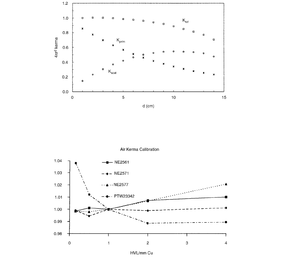
Ionization Chamber Dosimetry 179
calibration factors for the NE2561 and NE2571 vary by
less than 1% between 0.15 mm Cu and 4 mm Cu. The
responses of the (short) NE2577 and PTW Grenz ray
chambers are slightly less flat, varying by 2% and 4%,
respectively. If the NACP electron chamber is included,
the variation becomes much greater (25%).
For Farmer types of chamber, the variation in response
with HVL has been extracted from data measured during
routine calibration. This is shown in Figure 3.88, normal-
ized to 3.5 mm Cu.
As can be seen, the variation of response for the
NE2581 is greater than might be expected. Although this
graph is plotted over a greater range (down to 0.068 mm
Cu), there is still about a 15% difference between 1.0 and
0.15 mm Cu, with significant variation between individual
chambers. Experience suggests that this may also be typ-
ical of chambers of the Farmer type which use either
conducting or graphite-coated plastic outer electrodes.
Experimental investigation of a simple design of a
plane-parallel electron chamber, which has very thin lay-
ers of copper (0.018 or 0.035 mm) as conducting material
was done by Ma et al.[93] The results show that the
factors (proportional to the product of water/air stopping
power ratio and perturbation factor) for converting the in-
phantom air-kerma-calibrated chamber reading to the
absorbed dose to water are nearly constant for incident
electron energies between 4 and 11 MeV for prototype
chambers with 0.018-mm-thick copper layers and between
4 and 15 MeV for chambers with 0.035-mm-thick copper
layers.
FIGURE 3.85 Calculated total kerma is split into separate contributions of scattered and primary photons. The kerma are multiplied
by . At distances larger than 6 cm, the scatter contribution is larger than that of the primaries. The results are normalized at
1 cm. This figure can be compared with the results obtained by Russell and Ahnesjö. [91a] (From Reference [91]. With permission.)
FIGURE 3.86 The variation of the chamber calibration factor with beam quality. (From Reference [92]. With permission.)
4
r
2
C
e
Ch-03.fm(part 2) Page 179 Friday, November 10, 2000 11:59 AM