Shani G. Radiation Dosimetry: Instrumentation and Methods
Подождите немного. Документ загружается.

160 Radiation Dosimetry: Instrumentation and Methods
where D is the percent depth dose and d is the depth at
which the chamber central axis is located. P
repl
values are
shown in Table 3.20.
Ma and Nahum [80] investigated the displacement-
effect corrections for ionization chambers calibrated in air
in terms of air kerma and used at a depth in a phantom
irradiated by medium energy x-ray beams for tube poten-
tials between 100 and 300 kV. The Monte Carlo code
system was used to simulate the coupled transport of pho-
tons and electrons.
The air kerma at a point, usually the center of the air
cavity of the chamber on an air cavity axis, that has a volume
defined by the outer dimensions of the ionization chamber
and the stem in the water phantom can be written as:
(3.149)
The air kerma at the depth of the chamber center in
water in the absence of the chamber can be written as
(3.150)
where
p
dis
is the displacement correction factor that
accounts for the effect of the displacement of water by the
ionization chamber. Equation (3.150) defines p
dis
as a ratio
of air kermas.
The air kerma K
air,u
can be converted to the water
kerma at the same point in water, K
w, u
, through the ratio
of the mass energy absorption coefficients for water to air
averaged over the photon fluence at the same point in the
undisturbed phantom, ( /
)
w,air
.
In order to obtain the displacement correction factor,
p
dis
, one must first calculate air kermas K
air,u
and .
(3.151)
and
(3.152)
where and are averaged over the
photon fluence’ and primary and scattered, respectively.
In general, the difference between and
is very small and therefore, according to Equa-
tion (3.150), we have
(3.153)
K
air u,
M
u
N
K
k
Q
K
air, u
K
air, u
p
dis
M
u
N
K
()k
Q
p
dis
en
TABLE 3.20
P
repl
factors for photon beams
Energy a
k (mm
–1
)
b c
60
Co 0.0040 0.0043 0.0030
5 MV 0.0040 0.0043 0.0026
8 MV 0.0031 0.0037 0.0022
16 MV 0.0024 0.0027 0.0020
42 MV 0.0025 0.0026 0.0016
Note: The measurement point was assumed to be at the central axis
of chamber, located at a depth of 5 cm for
60
Co and 10 cm for other
beams.
P
repl
1 kr, where r is chamber radius in mm; a: from
measured data of Johansson et al;
b: from Equation (3.148), using
BJR 17 depth-dose data; c: from AAPM TG-21 protocol.
Source: From Reference [78]. With permission.
K
air, u
K
wu,
K
air u,
en
/
()
w air,
K
wu,
K
air u,
en
/
()
w air,
en
/
()
w air,
en
/
()
w air,
en
/
()
w air,
en
/
()
w air,
p
dis
K
air,u
/K
air u,
K
wu,
/K
wu,
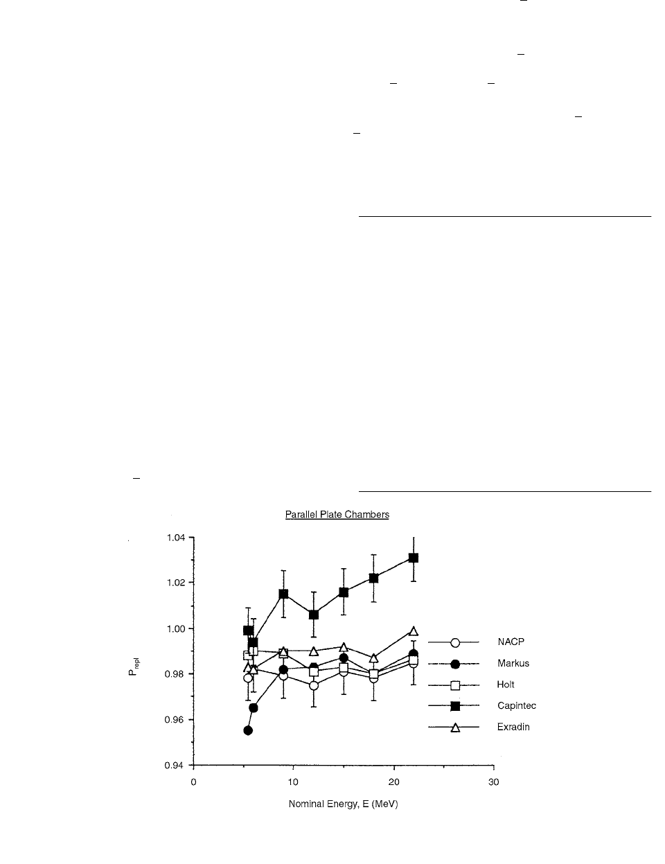
FIGURE 3.72 Experimental values of P
repl,pp,E
for the five parallel-plate chambers studied in this work. Error bars are 1%. (From
Reference [77]. With permission.)
Ch-03.fm(part 2) Page 160 Friday, November 10, 2000 11:59 AM
Ionization Chamber Dosimetry 161
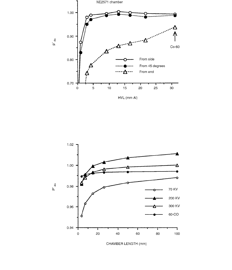
Figure 3.73 gives the values, calculated using the
simple attenuation and scattering method for a stemless
NE2571 chamber of 7.4-mm outer diameter and 26-mm
length for photon beams incident from different angles.
varies with both photon energy and incident angle.
It decreases rapidly with photon energy for low-energy
photons.
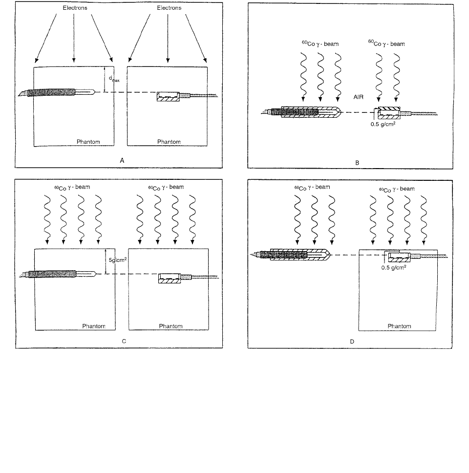
Figure 3.74 shows the dependence of on chamber
length for photons incident at a 90° angle. At 200 kV,
is 1.011 for 100-mm length but decreases to 1.003 for the
dimensions of an NE2571 chamber. For
60
Co gamma-rays,
increases with chamber length and stabilizes at about
0.994 0.001 for chamber length greater than 50 mm.
Further calculations show that for a 7.4-mm diameter and
FIGURE 3.73 The displacement corrections for an NE2571 chamber, calculated using the simple attenuation and scattering method
as ratios of the water kerma in a water cylinder of 7.4-mm diameter and 26-mm length, , to the water kerma in a low-density
(the same as that of air) water cavity, , for x-ray beams incident from either the side or the end of the water cylinder, or at a
45° angle (note that the quality of the
60
Co beam does not correspond to the HVL value). The statistical uncertainty in the calculated
kerma ratios is about 0.2%. (From Reference [80]. With permission.)
FIGURE 3.74 The variation of the displacement correction factor with chamber length for a chamber of 7.4-mm outer diameter,
calculated using the simple attenuation and scattering method for 70, 200, and 300-kV photons and
60
Co gamma-rays incident from
the side (90°). The statistical uncertainty in the calculated kerma ratios is about 0.1%. (From Reference [80]. With permission.)
K
wu,
K
wu,
p
dis
p
dis
p
dis
p
dis
p
dis
Ch-03.fm(part 2) Page 161 Friday, November 10, 2000 11:59 AM
162 Radiation Dosimetry: Instrumentation and Methods
7.4-mm long cylinder, is 0.991, while decreases
to 0.988 if the beam is incident on the end wall of the
cylinder (i.e., 0°) rather than on the side wall (i.e., 90°).
For a cylinder of 7.4-mm diameter and 7.4-mm length,
values are smaller than unity for photon energies
throughout the medium-energy range.
IX. IONIZATION CHAMBER CALIBRATION
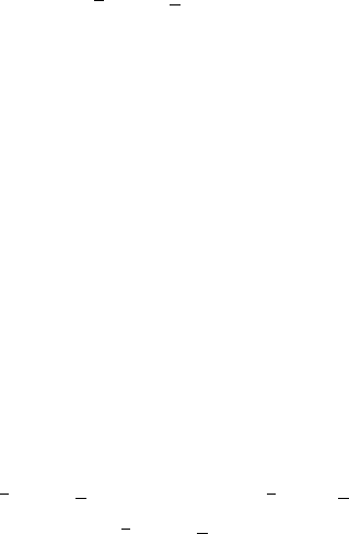
Several methods for the calibration of plane-parallel
chambers have been reported in the literature. These are
shown in Figure 3.75 and can be described as follows. [81]
1. Calibration with high-energy electrons in phan-
tom. The location of the point of measurement
is taken as the center of the cylindrical chamber
and the inner surface (of the wall that is prox-
imal to the source) of the plane-parallel cham-
ber, respectively. The point for each chamber is
placed at
d
max
for the ionization curve, as deter-
mined by measurement for the electron beam
being used, and the field size is measured at the
phantom surface Figure 3.75a.
2. ‘‘In-air” calibration of a plane-parallel cham-
ber using a
60
Co beam with a fixed source-to-
detector distance (SDD) and field size (FS),
p
dis
p
dis
p
dis
FIGURE 3.75 Schematic illustration of the irradiation geometries used for making calibrations of parallel-plate chambers with
cylindrical chambers. (A) Calibration with 20-MeV electrons. The cylindrical chamber is aligned with the midpoint of its collecting
volume, located on the beam axis at
d
max
, and its axis of rotation, perpendicular to the beam axis. The midpoint of the inner surface
of the front wall of the plane-parallel chamber is located on the beam axis, and the chamber walls are perpendicular to that
axis. (B) ‘‘In-air” calibration of a parallel-plate chamber using a
60
Co beam. Point of measurement taken as the chamber center.
(C) Calibration ‘‘in phantom at depth,” with a
60
Co beam. Both chambers are placed in phantoms at depth of 5 g/cm
2
. Point of
measurement taken as the center of the cylindrical chamber and the inner surface of the proximal electrode of the plane-parallel
chamber. (D) Calibration ‘‘in phantom at dose maximum,” with a
60
Co beam. The parallel-plate chamber was placed in the phantom
with full backscatter at
d
max
(determined by measurement). Point of measurement taken as the chamber center. In all cases, the
cylindrical chamber is shown on the left and the plane-parallel chamber is on the right. (From Reference [81]. With permission.)
Ch-03.fm(part 2) Page 162 Friday, November 10, 2000 11:59 AM

Ionization Chamber Dosimetry 163
measured at the SDD, with the point of mea-
surement being taken as the chamber center, and
with build-up cap required for both chambers
(Figure 3.75b).
3. Calibration ‘‘in phantom at depth,” with a
60
Co
beam, both chambers being placed in phantoms
at depth d 5 g/cm
2
. The point of measurement
is taken as the center of the cylindrical chamber
and at the inner surface (of the wall that is
proximal to the source) of the plane-parallel
chamber Figure 3.75c.
4. Calibration ‘‘in phantom at dose maximum,”
with a
60
Co beam. The plane-parallel chamber
is placed in the phantom at d
max
with full back-
scatter (determined by measurement). The
point of measurement is taken as the chamber
center. The SDD and field size are the same as
for the ‘‘in-air” method. The comparison is
made with a cylindrical chamber irradiated in
air (Figure 3.75d).
5. Method (d) is essentially the same as method (b),
the two being related by the backscatter factor.
There are only three independent methods, (a),
(b), and (c), and these are described in this
report; method (d) is not recommended.
Method (a) employs high-energy electrons,
method (b) makes use of a
60
Co gamma-ray beam
with the chambers located at a point in air, and
method (c) also employs a
60
Co beam but with
the chambers placed at depth in a phantom.
N
gas
for a plane-parallel chamber may be determined
as follows. Using the highest electron-beam energy avail-
able and the cylindrical chamber for which N
gas
is known,
determine the response per monitor unit at d
max
. Next,
place the plane-parallel chamber into the same dosimetry
phantom, taking care to position the inner surface of its
proximal electrode at the depth of the central axis of the
cylindrical chamber, and determine its response per mon-
itor unit. The cavity gas calibration factor for the plane-
parallel chamber is given by [82]
(3.154)
where the terms in the numerator apply to the cylindrical
chamber and those in the denominator apply to the plane-
parallel chamber.
N
gas
is the dose to the gas in the chamber
per electrometer reading (Gy/C or Gy/scale division) M,
P
ion
is the factor that corrects for ionization recombination
losses, and P
repl
is the replacement correction factor. M is
the electrometer reading (C or scale division), and it rep-
resents the measured average ionization for positive and
negative polarities, in Coulombs or scale division, cor-
rected to air density at 22°C, 760 mm Hg, but not corrected
for relative humidity, assuming it to be typical of labora-
tory conditions (50% 25%).
The highest electron-beam energy available must be
high enough to make the P
repl
value for the cylindrical
chamber no smaller than 0.98. For a typical Farmer-type
cylindrical chamber of inner diameter 6.3 mm, an electron
beam is required, with a mean energy of at least 10 MeV
at d
max
, the depth of the measurement required. The mean
energy at depth is related approximately to the mean inci-
dent energy.
Electron-beam diameters should be large enough to
provide complete in-scattering to the beam axis. Conser-
vatively, this requires a beam diameter of twice the range
R of the electrons in the phantom medium. Thus, a beam
diameter (cm) numerically equal to the incident electron
energy (MeV) is ample, assuming unit density.
The quantity in Equation (3.154) is derived from
the NIST calibration value of or for the chamber.
TABLE 3.21
Recommended Values of /(N A
ion
)
PP
and /(N
K
A
ion
)
PP
for Five Commercially
Available Plane-Parallel Chambers
Chamber
Build-up
a
material
or phantom material A
wall
K
comp
and /(N
x
A
ion
)
PP
(10
–3
Gy/R) /(N
K
A
ion
)
pp
Capintec Polysty 1.0022 0.960 8.84 1.005
PS-033
Exradin P-11 Polysty 1.0016 1.000 8.48 0.964
Holt Polysty 1.0097 1.000 8.55 0.972
NACP Graphite 1.0016 1.027 8.45 0.961
PTW-Markus Acrylic 1.0030 1.000 8.59 0.977
Factors to be applied in the calibration and use of plane-parallel chambers.
a
The build-up material of thickness 0.5 g/cm
2
is added to the front face of the chamber, except for the Holt in which the
build-up material is inherent in the design.
Source: From Reference [81]. With permission.
N
gas
PP
N
gas
PP
P
wall
pp
N
wall
pp
N
gas
pp
N
gas
pp
MN
gas
P
ion
P
repl
()
cyl
/ MP
ion
()
pp
N
gas
cyl
N
x
cyl
N
K
cyl
Ch-03.fm(part 2) Page 163 Friday, November 10, 2000 11:59 AM
164 Radiation Dosimetry: Instrumentation and Methods
Equation (3.155) relates to , based on the con-
ditions present during the NIST calibration of the chamber
in a
60
Co gamma-ray beam:
(3.155)
where is stated in R/C, R/scale division, Ckg
1
/C, or
Ckg
1
/scale division; k 2.58 10
4
CKg
1
R
1
or unity
if exposure is stated in Ckg
1
; and (W/e)
gas
33.7 J/C.
A
ion
is the ion-collection efficiency, at the time of calibra-
tion. A
wall
is the correction factor for attenuation and scat-
tering of gamma-rays in the chamber wall and buildup
cap.
wall
is the quotient of absorbed dose by the collision
kerma in the chamber wall;
wall
1.005 for
60
Co gamma-
rays. is the mean restricted mass stopping power
ratio for the chamber wall material, relative to the gas
(ambient air) inside. is the mean mass energy
absorption coefficient ratio for dry air relative to the cham-
ber wall material. K
comp
corrects for the composite nature
of the chamber and build-up cap. For a cylindrical cham-
ber and buildup cap, it is given by [81]
(3.156)
where
is the fraction of ionization due to electrons
arising from photon interactions in the chamber wall and
(1
) is the fraction of ionization due to electrons arising
from photon interactions in the build-up material.
If the NIST calibration of the cylindrical chamber is
stated as an air-kerma calibration factor, N
K
in Gy/C, the
value of N
X
, in R/C for use in Equation (3.155), can be
obtained from
(3.157)
where
g is the average fraction of secondary electron
kinetic energy that is spent in bremsstrahlung production.
NIST takes g as 0.0032 and (W/e)
air
for dry air as 33.97
J/C for
60
Co gamma-rays. Thus, for these values, N
x
113.7N
K
. Recommended values of N
gas
/N
x
A
ion
for the
cylindrical chambers commonly used can be found in
Gastorf et al. [83] N
gas
/N
K
A
ion
values can be determined
using Equation (3.157).
In the
60
Co in-air method, the intercomparison between
the plane-parallel chamber and the NIST calibrated spher-
ical or cylindrical chamber is performed in a
60
Co gamma-
ray beam in air. An exposure or air-kerma calibration factor
or will be obtained for the plane-parallel chamber
by direct comparison with the spherical or cylindrical
chamber and is obtained from given
values. The following procedures should be followed: [81]
1. The plane-parallel chamber should be submit-
ted to the ADCL for calibration with the nec-
essary dose build-up material in place, unless
the proximal wall is already thick enough, as
is the case for the Holt chamber. The added
build-up material should have the same outer
diameter as the chamber and be of the material
specific in Table 3.21; its thickness should
be 0.5 g/cm
2
to ensure charged-particle equi-
librium, exclude electro-contamination that
may be present in the
60
Co beam, and match
the calculated A
wall
values given in Table 3.21.
2. The
60
Co beam should be 10 10 cm
2
at the
chamber measurement location, at a distance of
at least 80 cm from the source.
3. The correct alignment of the plane-parallel
chamber for the intercomparison is with the
midpoint of its ion-collecting volume located
on the beam axis at the measurement location
and its flat chamber walls perpendicular to that
axis. This is the point of measurement for in-air
calibrations only and is required by the ion
chamber theory used to extract N
gas
. Similarly,
the use-provided build-up cap material must be
in place for the in-air calibration only.
In the
60
Co in-phantom method, the intercompari-
son between the plane-parallel chamber and the NIST-
calibrated cylindrical chamber is performed in a
60
Co
gamma-ray beam at a depth of 5 g/cm
2
in a phantom of
material selected to match that of the plane-parallel cham-
ber. is related to the known value of by
(3.157)
where
M
cyl
and M
pp
are, respectively, the meter readings
of the cylindrical and plane-parallel chambers under the
above conditions, corrected for temperature and pressure,
and M
pp
is the average of each polarity. A
ion
is the ion-
collection efficiency at the time of calibration; is
obtained from the NIST calibration value of or ;
P
repl
is the correction factor for the replacement of phan-
tom material by the cavity of the ionization chamber [P
repl
is taken as unity in the 1983 AAPM protocol for plane-
parallel chambers, so it does not appear on the left-hand
side of Equation (3.157)]; and P
wall
is the correction factor
to account for the chamber material being different from
that of the phantom.
P
wall
for the plane-parallel chamber is difficult to deter-
mine. In the ideal case, where the plane-parallel chamber
N
gas
cyl
N
x
cyl
N
gas
cyl
N
x
cyl
kW/e()
gas
A
ion
A
wall
wall
L/
()
gas
wall
en
/
()
wall
air
K
comp
cyl
----------------------------------------------------------------
N
x
cyl
L
()
gas
wall
en
/
()
wall
air
K
comp
cyl
L/
()
gas
wall
en
/
()
wall
air
1
()L/
()
gas
cap
en
/
()
cap
air
L/
()
gas
wall
en
/
()
wall
air
------------------------------------------------------------------------------------------------------------------------
N
x
N
K
1 g() We()
air
N
x
pp
N
K
pp
N
gas
pp
N
gas
pp
/ N
x
A
ion
()
pp
N
gas
pp
N
gas
cyl
M/A
ion
()
pp
N
gas
P
wall
()
pp
M/A
ion
()
cyl
N
gas
P
repl
P
wall
()
cyl
N
gas
cyl
N
x
cyl
N
K
cyl
Ch-03.fm(part 2) Page 164 Friday, November 10, 2000 11:59 AM

Ionization Chamber Dosimetry 165
is made of only a single material that is identically matched
by the phantom medium, P
wall
equals unity. However, the
construction of plane-parallel chambers usually employs
more than one material. Thus, the phantom medium should
be selected to match whichever material is the most impor-
tant contributor of the secondary electrons that produce the
measured ionization.
If the chamber has a very thin front wall (for which
is nearly zero), its influence can be ignored because
practically all of the electrons then originate in the phan-
tom medium. That medium should be selected to match
the principal material of which the thicker rear wall is
constructed. Since secondary electrons are projected pref-
erentially in the forward hemisphere by
60
Co gamma-ray
interactions, the electron backscattering ability of the rear
wall (a strong function of atomic number) will be the most
important influence on the ionization. If the chamber has
a thicker front wall, for
which is significantly greater
than zero, the phantom medium should be made of that
same material. However, if the back wall differs apprecia-
bly in atomic number, this in-phantom procedure should
not be expected to yield a satisfactory result, due to the
difference in electron backscattering from the back wall
in comparison with the phantom medium.
Once has been calculated, the determination of
absorbed dose for the user’s beam will proceed according
to TG-21. Since these chambers are designed primarily
for use with electron beams, calibration of those beams
only will be presented. When the chamber is placed in a
suitable phantom (medium), the dose to the medium will
be given by
(3.158)
where M is the electrometer reading (Coulombs or scale
division corrected to 22°C, 760 mm Hg). is the
ratio of the mean, restricted collision mass stopping power
of the phantom material to that of the chamber gas (ambi-
ent air). P
ion
is the factor that corrects for ionization recom-
bination losses that occur at the time of calibration of the
user’s electron beam.
In the 1983 AAPM protocol, the replacement correc-
tion factor P
repl
is taken as unity for plane-parallel cham-
bers, irrespective of electron-beam energy. Two of the
commercial chambers (Capintec and Markus) show clear
experimental evidence that P
repl
decreases with decreasing
electron energy. The Netherlands Commission on Radia-
tion Dosimetry, in their Code of Practice of the Dosimetry
of High-Energy Electron Beams, considered this situation
for the Markus chambers and recommended the following
equation for P
repl
(designated p
f
in their protocol):
(3.159)
For five commonly used parallel-plate ion chambers,
Monte Carlo calculations of the wall attenuation and
scatter correction factors (
K
wall
or ) and the
correction for nonhomogeneous composition of the cham-
ber (K
comp
or related to k
m
) were presented by Rogers.
[84] The chambers were assumed to have 0.5 g/cm
2
build-up caps made of the predominant material in each
chamber. These correction factors are needed if air-
kerma calibration factors are used to deduce the cham-
ber’s cavity-gas calibration factor, N
gas
. The scatter from
the material around the cavity more than compensates
for the attenuation in the front wall and, hence, K
wall
values are less than unity. Thin collectors or insulators
behind the collecting volume can have a major effect
because electron backscattering depends strongly on
material.
The AAPM’s TG-21 dosimetry protocol recommends
calibrating parallel-plate ion chambers by establishing the
dose in a high-energy electron beam using a calibrated
cylindrical ion chamber and then using this dose to estab-
lish the calibration of the parallel-plate chamber. By equat-
ing the dose measured at
d
max
in an electron beam using
cylindrical and parallel-plate ion chambers, one finds by
following TG-21 that
(3.160)
where the charge readings from ion chambers are repre-
sented by
M and are understood to be corrected for tem-
perature, pressure, ion recombination, and polarity effects.
If an electron beam is not to be used, there are two
options: base the calibration on an in-air air-kerma cali-
bration factor, , or base
the calibration on an in-phantom absorbed-dose calibra-
tion factor, N
D
, or equivalent.
If the in-air route is chosen, N
gas
is determined from
(3.161)
where N
K
is the air-kerma calibration factor, is the
fraction of the electron’s energy lost by radiative pro-
cesses, K
wall
( ) corrects for the lack of charged-
particle equilibrium in the chamber walls (caused mostly
by photon attenuation and scatter), corrects for any
charge-collection losses in the calibration beam, and K
comp
corrects for any components in the chamber made of mate-
rials different from the wall material.
If the calibration of the parallel-plate chamber is done
starting from an absorbed-dose measurement in a phantom,
N
gas
pp
D
med
MN
gas
pp
L/
()
gas
med
P
ion
P
repl
L/
()
gas
med
P
repl
1 0.041e
0.4E
z
A
wall
1
K
att
1
K
wall
N
gas cyl,
M
cyl
P
repl
cyl
P
wall
cyl
M
pp
P
repl
pp
P
wall
pp
------------------------------
Gy/C()
N
K
N
K
N
X
W/e
air
/1
g
()()[]
N
gas
N
K
1 g()
L/
()
air
wall
en
/
()
wall
air
K
wall
K
comp
K
ion
c
-------------------------------------------------------------------------------
GyC
1
()
g
A
wall
1
K
ion
c
Ch-03.fm(part 2) Page 165 Friday, November 10, 2000 11:59 AM

166 Radiation Dosimetry: Instrumentation and Methods
one has [84]
(3.162)
where N
D
is the absorbed dose to the phantom material
per unit charge from the parallel-plate chamber (corrected
for ion recombination and polarity effects), P
wall
corrects
for the replacement of the phantom material by the mate-
rial in the ion chamber, and P
repl
corrects for the effects
of the cavity on the electron fluence in the phantom at the
point of measurement. This equation is the basis of many
proposals and measurements related to determining N
gas
for parallel-plate ion chambers, where N
D
is usually deter-
mined using a calibrated cylindrical ion chamber in the
same phantom. In most cases, the phantom material is the
same as the material of the parallel-plate chamber and,
hence, P
wall
is taken as unity, as is P
repl
. Note, however,
that in a
60
Co beam for an ion chamber in a phantom or
free in air with a build-up cap of the phantom material,
P
wall
and K
comp
correct for the same physical effect. K
comp
corrects the chamber response for the fact that not all of
the chamber is made of the same material as the build-up
cap.
Results for the standard configurations are shown in
Table 3.22. The K
wall
factors are all less than unity, which
means that photon scatter is more important than attenu-
ation. With the exception of the Holt chamber, which
comes in a slab-phantom, the chambers have a K
wall
value
within 0.1% of 0.998. This should be compared to a typ-
ical value of 1.010 for a cylindrical thimble chamber with
a 0.5 g/cm
2
wall, in which case the photon attenuation
dominates the scatter. The value of 0.9904 for the Holt
chamber is 0.3% greater than the previous value published
using this computer code. This may be attributed mainly
to improved statistical precision (0.04% here vs. 0.2%
previously) and somewhat (0.1%) to the fact that the cur-
rent calculations are for a 100-cm
2
beam, whereas the
previous ones were for a broad beam.
The effects of using different buildup caps have been
investigated for the Markus, NACP, and Capintec cham-
bers. The results in Table 3.23 show some results. Effects
of the build-up caps on the calculated values of k
m
for
heterogeneous chambers do not follow what is expected
from a naive theory, in which the k
m
value of the chamber
is assumed to behave as the k
m
value of the cap. [84]
It was shown by Rogers [85] that basing clinical
dosimetry on absorbed-dose calibration factors N
D
leads
to considerable simplification and reduced uncertainty in
dose measurement. A quantity k
Q
is defined which relates
an absorbed-dose calibration factor in a beam of quality
Q
0
to that in a beam of quality Q. For 38 cylindrical ion
chambers, two sets of values were presented for N
D
/N
X
TABLE 3.22
Calculated Values of K
wall
and K
comp
for the 5 Parallel-Plate
Chambers, Each with a 0.5-g/cm
2
Build-Up Cap of the Chamber’s
Predominant Material Added to the Front Face (except for the Holt
chamber)
Chamber Cap Material K
wall
A
wall
k
att
k
m
K
comp
k
att
Capintec polystnoy 0.9978(4) 1.0022(4)
a
1.020(4)
a
0.952(4) 1.022(4)
Exradin P
11b
polystnoy 0.9984(3) 1.0016(3) 0.971(4) 1.000(4) 0.973(4)
Holt
b,d
polystnoy 0.9904(4) 1.0097(4) 0.974(5) 0.997(5) 0.983(5)
Markus
b
PMMA 0.9970(6) 1.0030(6) 0.982(4) 1.000(4) 0.985(4)
NACP graphite 0.9984(2) 1.0016(2) 0.973(3) 1.027(3) 0.975(3)
Note: The collector and/or insulators were included in the calculations. All cases are for a point source
with a
60
Co spectrum at a distance of 80 cm from the front face of the build-up cap. For in-air
measurement, the point of measurement is the midpoint of the air cavity. One-standard-deviation
statistical uncertainties in the last digit are shown in brackets. Estimated systematic uncertainties are
1% for k
m
and K
comp
and 0.05% for K
wall
or A
wall
.
a
Results for the Capintec chamber using a radius of 1. 6 cm are 0.1% less, i.e., insignificantly different.
This means the approximation of a square detector by a circular one has no effect on these results.
Recall that stem effect corrections must be used with this detector.
b
No insulator.
c
Note: N
gas
/N
K
k
att
k
m
(l g) where g 0.003. Alternatively, N
gas
/N
X
(W/e)k
att
k
m
[J/C] for N
X
in
C/kg or N
gas
/N
x
8.764 10
–3
k
att
k
m
[Gy/R] for N
X
in R/C.
d
Holt chamber results are for a beam area of 100 cm
2
.
Source: From Reference [84]. With permission.
A
att
1
k
att
1
,k
m
,
k
m
c
N
gas
N
D
P
wall
P
repl
L/
()
air
water
[]
Co
60
--------------------------------------------------------
GyC()
Ch-03.fm(part 2) Page 166 Friday, November 10, 2000 11:59 AM

Ionization Chamber Dosimetry 167
and N
gas
/N
D
, and for k
Q
for photon beams with beam qual-
ity specified by the ratio. One set is based on TG-
21’s protocol to allow the new formalism to be used while
maintaining equivalence to the TG-21 protocol. To dem-
onstrate the magnitude of the overall error in the TG-21
protocol, the other set uses corrected versions of the
TG-21 equations and the more consistent physical data of
the IAEA Code of Practice.
Given , the absorbed dose-to-water calibration
factor for an ion chamber in a beam of quality Q, and
under reference conditions of field size and depth:
(3.163)
where is the absorbed dose to water at the location
of the center of the ion chamber when it is absent; the ion
chamber reading M has been corrected to reference con-
ditions of temperature and pressure; and corrects for
lack of complete charge collection in the user’s beam and
must be measured for each beam quality. This definition
of is analogous to the definition of the exposure cal-
ibration factor given by , where X is the
exposure at the location of the center of the ion chamber
(except that in the absorbed-dose equation, the cor-
rection is made explicit because its effects are not negli-
gible, unlike the normal case for exposure measurements).
The following dose equation from the AAPM protocol
also applies:
(3.164)
In the case where the absorbed-dose calibration factor
is known in some other beam quality , let be
a factor which accounts for changes in the calibration
factor between beam quality and
Q; i.e.,
(Gy/c) (3.165)
and from Equation (3.163):
(Gy) (3.166)
Equations (3.163) and (3.164) give
(Gy/c) (3.167)
Eliminating from this equation by using the analogous
equation for a beam of quality allows one to solve for :
(3.168)
The quantity relates the absorbed-dose calibration fac-
tor in a beam of quality
Q to that for a beam of quality
in the same medium. From the user’s point of view,
this is the simplest possible approach since it uses a cor-
rection factor which is conceptually very straightfor-
ward yet takes into account all of the physics.
A computer program, called PROT, has been written
to calculate and other protocol-related quantities for
photon beams as a function of beam quality Q for an
arbitrary ion chamber in a phantom of water, PMMA, or
polystyrene. The program calculates using the equa-
tions and data of the original TG-21 protocol or using the
TG-21 equations with the more consistent physical data
of the IAEA Code.
Conversion from to (in a
60
Co beam) gives
(Gy/R) (3.169)
where is in R/C [divide by
(C/kg)/R to get the result in Gy/(C/kg), for use with
when using the SI unit for exposure C/kg]. The
formalism can be applied to cases of electron beams
as well as photon beams. Conceptually, it loses its sim-
plicity somewhat because different quantities are involved
in the ratio for for electron and photon beams and
because becomes a function of both the beam quality
Q and the depth of dose maximum.
To investigate the relative merits of using an absorbed
dose calibration–based approach vs. an in-air calibration
factor–based approach, one must first define the optimal
approach based on the in-air calibration factors. This can
TABLE 3.23
Calculated Effect on k
m
and K
wall
of Changing the
Material of the 0.5-g/cm
2
Build-Up Cap for the
NACP, Markus, and Capintec Chambers
Chamber k
m
K
wall
k
att
k
m
Capintec
polyst cap 1.020(4) 0.9978(4) 1.022(4)
PMMA cap 1.008(3) 0.9981(4) 1.010(3)
graphite cap 1.018(3) 0.9964(4) 1.022(3)
Markus
polyst cap 1.000(4) 0.9972(4) 1.003(4)
PMMA cap 0.982(4) 0.9970(6) 0.985(4)
graphite cap 0.984(3) 0.9949(4) 0.989(3)
NACP
polyst cap 0.984(3) 1.0003(3) 0.982(3)
PMMA cap 0.977(5) 1.0007(3) 0.976(5)
graphite cap 0.974(3) 0.9984(2) 0.975(3)
Source: From Reference [84]. With permission.
TPR
10
20
N
D
Q
D
water
Q
MP
ion
N
D
Q
D
water
Q
P
ion
N
D
Q
N
X
XMN
x
P
ion
D
water
Q
MP
ion
N
gas
P
wall
P
repl
L
()
air
water
[]
Q
N
D
Q
Q
0
k
Q
Q
0
N
D
Q
k
Q
N
D
Q
0
D
water
Q
MP
ion
k
Q
N
D
Q
0
N
D
Q
N
gas
P
wall
P
repl
0
L
()
air
water
[]
Q
N
gas
Q
0
k
Q
k
Q
P
wall
P
repl
L
()
air
water
[]
Q
P
wall
P
repl
L
()
air
water
[]
Q
0
----------------------------------------------------
k
Q
Q
0
k
Q
k
Q
k
Q
N
X
N
D
N
D
N
X
-------
N
gas
N
X
---------
P
wall
P
repl
L
()
air
water
[]
Co
60
N
X
N
D
N
X
2.58 10
4
N
X
kg
1
k
Q
k
Q
k
Q
Ch-03.fm(part 2) Page 167 Friday, November 10, 2000 11:59 AM
168 Radiation Dosimetry: Instrumentation and Methods
best be done by starting from an air-kerma calibration
factor and defining a single
factor, , to relate the ion-chamber readings in phantom
M to the dose to the medium; i.e., is defined such that:
(Gy) (3.170)
This is usually accompanied by requiring use of one of a
few specified types of ion chambers. Using Equation
(3.164) for the dose to the medium and substituting the
relationship between and gives:
(3.171)
One of the advantages of using this approach rather than
the and approach is that is within about 10%
of unity.
The approach was introduced to make use of an
in-air calibration as simple as possible and analogous to
the procedure in practical terms. This bypasses the
equivalent, now traditional approach of the AAPM TG-21
protocol where Equation (3.170) can be written:
(Gy) (3.172)
with a corrected equation for given by
(Gyc
1
) (3.173)
where has the standard meaning but has been written
in terms of the air-kerma calibration factor. In using this
approach, the complexities of using an in-air calibration
factor are handled within the factor .
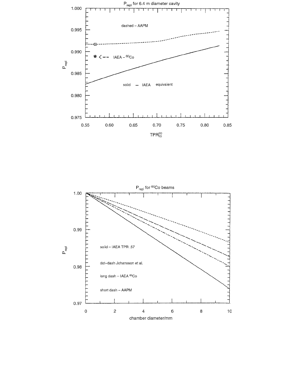
Figure 3.77 shows the size of the differences between
the AAPM value of and the effective value of
used by the IAEA Code for a cavity diameter typical of
a Farmer-like chamber. In photon beams, this is the only
difference between the physics in the AAPM TG-21 pro-
tocol and IAEA Code of Practice (ignoring aluminum
electrode differences, after corrections, and using the same
data sets).
Note that the IAEA’s effective for
60
Co is not on
the curve for the values commonly found for
60
Co
beams because the offset for
60
Co beams is different than
for all other beams. The net effect is that values for
the IAEA Code do not go to unity for values near
0.57, which is a typical value for a
60
Co beam. [85]
Figure 3.78 presents a comparison of various ,
correction factors as a function of cavity diameter in a
60
Co beam. The upper curve is that from the TG-21 pro-
tocol. The long dashed and solid curves are those given
by the IAEA offsets in the effective point of measurement,
as defined explicitly for a
60
Co beam (long dash) or assum-
ing a general beam with of 0.57 (solid). The final
dashed-dot curve represents the values implied by the
original data of Johanson et al. [72], on which the IAEA’s
offsets are based. These are significant differences which
deserve further research.
Figure 3.79 presents curves for a more restricted
situation, namely for Farmer-like chambers. In this case
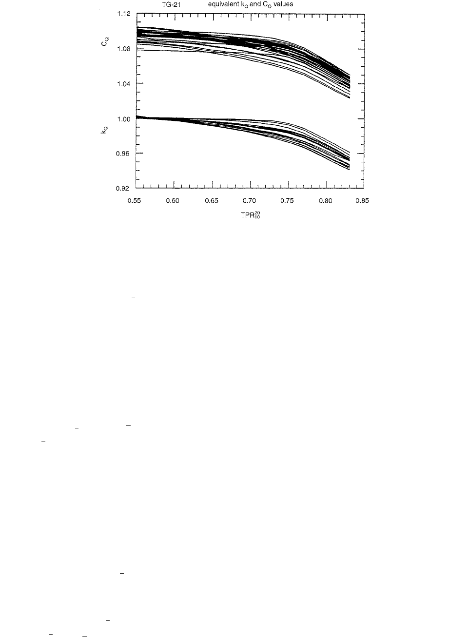
FIGURE 3.76 Plots vs. of TG-21 equivalent values of and values for the chambers discussed by Rogers. There is
a reduction in chamber-to-chamber variation obtained by using the approach, although the functional shape for a given detector
is the same in each case. (From Reference [85]. With permission.)
TPR
10
20
k
Q
C
Q
k
Q
N
K
N
X
We()
air
1 g()[]
C
Q
C
Q
D
med
MP
ion
N
K
C
Q
N
K
N
X
C
Q
1 g()P
wall
P
repl
L
()
air
med
[]
Q
L
()
air
wall
en
()
wall
air
K
wall
K
comp
K
ion
C
[]
Co
60
--------------------------------------------------------------------------------------------
N
gas
N
X
C
Q
C
Q
k
Q
D
med
MP
ion
N
gas
P
wall
P
repl
L
()
air
med
[]
Q
N
gas
N
gas
N
K
1 g()
L
()
air
wall
en
()
wall
air
KK
ion
C
------------------------------------------------------------
N
gas
N
gas
P
repl
P
repl
P
repl
TPR
10
20
k
Q
TPR
10
20
P
repl
TPR
10
20
k
Q
Ch-03.fm(part 2) Page 168 Friday, November 10, 2000 11:59 AM
Ionization Chamber Dosimetry 169
there is only a 0.7% variation about a “neutral” median
value. This is given accurately by any of the PMMA-
walled Farmer chambers, which are what make up the
dark central group in Figure 3.79. Alternatively, the
formula
(3.174)
FIGURE 3.77 Comparison of the AAPM TG-21 values of and the value of the equivalent correction in the IAEA Code of
Practice for a 6.4-mm diameter Farmer-like chamber as a function of beam quality, specified as . The symbols show the values
specified for
60
Co beams. (From Reference [85]. With permission.)
FIGURE 3.78 Comparison, as a function of chamber diameter, of the effective values of the replacement correction factor given by
a variety of approaches. The upper short-dash curve is that given by TG-21. The long-dash curve is equivalent to the offset
recommended by the IAEA for a
60
Co beam, whereas the solid curve is the same quantity for a beam with a value of 0.57.
The dot-dash curve is based directly on the data of Johansson
et al., upon which the IAEA approach was based. (From Reference
[85]. With permission.)
P
repl
TPR
10
20
TPR
10
20
K
Q
Q() 1.0 0.0215 TPR 0.57()
0.736 TPR 0.57()
2
Ch-03.fm(part 2) Page 169 Friday, November 10, 2000 11:59 AM