Shani G. Radiation Dosimetry: Instrumentation and Methods
Подождите немного. Документ загружается.

340 Radiation Dosimetry: Instrumentation and Methods
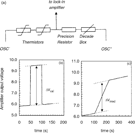
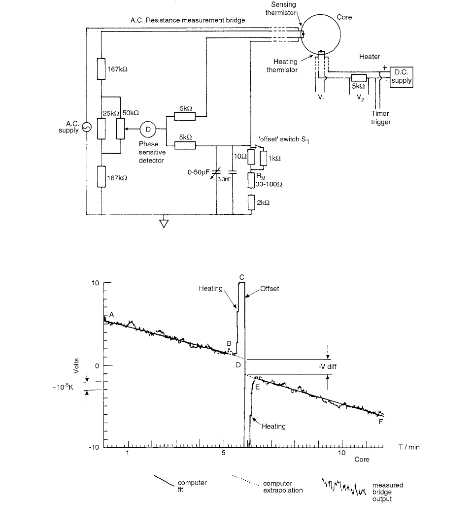
using the measuring bridge that is shown schematically in
Figure 6.13a. Two thermistors are serially connected in
one arm of the a.c. bridge, and in the opposite arm a fixed
high-precision resistor and a variable resistor are con-
nected to compensate the bridge. The out-of-balance volt-
age is amplified by a lock-in amplifier. Figures 6.13b and
6.13c show a typical calorimeter run in the 10-MV photon
beam with first a “calibration run” and thereafter an “irra-
diation run.” The procedure used to determine the voltage
change at mid-run is shown. The calibration of the bridge
output voltage is performed in a “calibration run” by
adding a well-known resistor to the bridge circuit (oppo-
site arm as thermistors) and determining the correspond-
ing out-of-balance voltage. This calibration is then used
to derive the average fractional thermistor resistance
change R/R due to irradiation from the voltage change
at mid-run, V, during an “irradiation run.” On both cal-
ibration and irradiation runs, corrections for changes in
self-heating of the thermistors and for nonlinearity of the
bridge response are applied. T is calculated as T
R/RS, where S is the average thermistor sensitivity result-
ing from calibration of the thermistors against standard
thermometry. [11]
III. GRAPHITE CALORIMETER
Potentially, water calorimeters are most accurate, but they
are delicate systems and require considerable care to con-
trol the purity of the water and the effects of radiochemical
reactions occurring in it. The standard based on the graphite
calorimeter is improving continuously. Graphite calorim-
eters are stable and are very accurate. However, suitable
conversion procedures are necessary for establishing the
absorbed dose to water. A particular problem in graphite
calorimetry is gap effect and its corrections.
The primary standard of absorbed dose to water estab-
lished at ENEA for the
60
Co gamma-ray quality is based
on a graphite calorimeter and an ionometric transfer sys-
tem. [12] The graphite calorimeter is of the Domen type.
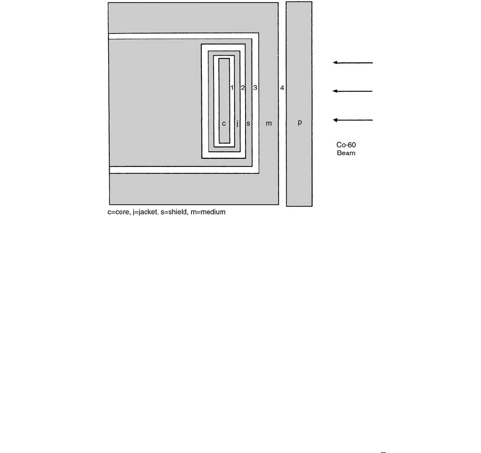
The gap configuration of the ENEA calorimeter is shown
in Figure 6.14. The four calorimeter bodies are enclosed
in a 1-cm-thick PMMA housing with 152-mm external
diameter. The external housing is radially surrounded by a
close-fitting 300-mm-diameter graphite annular body. It is
possible to increase the thickness of this annular body by
adding posterior 300-mm-diameter full backscattering
graphite plates and additional graphite front plates to
increase the measurement depth in graphite. The minimum
measurement depth (distance of the central plane of the
core from the calorimeter front surface) is 0.88 g cm
2
. The
calorimeter is thermoregulated at a temperature of about
27°C, with a stability better than 5 10
4
°C during a typical
measurement run. The jacket has approximately the same
heat capacity as the core, which is a disc of 20-mm diameter
and 2.75-mm thickness. In two holes radially drilled in the
core edge, two measuring thermistors are embedded, thus
doubling the sensitivity during measurements. Additional
thermistors are in the other calorimeter bodies (one ther-
mistor for each body) for temperature monitoring. Elec-
trical heaters are embedded in all of the four bodies of
the calorimeter. The heaters are manually operated to
inject heat amounts into each body for the calorimeter
electrical calibration and for controlling the heating or
cooling drifts in the different bodies. [12]
To transfer the dose from graphite to water, a thick-
walled (TW) ionization chamber is used. This is a cylin-
drical homogeneous chamber with graphite wall suffi-
ciently thick (0.5 g cm
2
) to allow electron equilibrium at
the
60
Co gamma radiation.
In each gap of the calorimeter there are three different
regions contributing in a different way to the variation of
the radiation fluence in the core. These regions are those
in front of (anterior gap), behind (posterior gap), and
around (annular gap) the core. The effects of these three
gap regions were evaluated, separately but a single correc-
tion was determined for the same region of all three gaps.
For conversion of the absorbed dose from graphite to
water, the TW chamber was irradiated in graphite phantom
at the same depth,
z(P
g
), where the absorbed dose to graph-
ite,
D
g
, was known by absolute measurement with the
calorimeter. A chamber calibration factor, N
g
, in terms of
absorbed dose to graphite, was then obtained as
(6.14)
FIGURE 6.13 (a) Schematic drawing of the a.c. measuring
bridge and typical time evolution of the bridge output voltage
during (
b) a “calibration run” and (c) an “irradiation run.” (From
Reference [11]. With permission.)
N
g
D
g
P
g
()QP
g
()
CH-06.fm Page 340 Friday, November 10, 2000 12:02 PM
Calorimetry 341
where Q(P
g
) is the ionization charge due to the absorbed
dose D
g
at P
g
. The chamber was then irradiated in the
water phantom at a depth z(P
w
), where the photon fluence
differential in energy was expected to be the same as that
existing at the reference depth z(P
g
) in the graphite phan-
tom. The “corresponding points”
P
w
and P
g
were deter-
mined according to the scaling rule derived from the
photon fluence scaling theorem
(6.15)
where
D
g
(P
w
) is the absorbed dose to graphite at the center
of a small mass of graphite placed in water with its center
in P
w
; Q(P
w
) is the corrected charge reading due to the
absorbed dose D
g
at P
w
.
The existence of transient electron equilibrium condi-
tions (TCPE) in that mass of graphite allows us to express
the absorbed dose given by Equation (6.15) also as
(6.16)
where
g
(P
w
) is the photon energy fluence at the center
of the mass of graphite placed in water at P
w
, (
en
/
)
g
is
the mass energy absorption coefficient in graphite aver-
aged over the photon energy spectrum, and
g
is the ratio
of the absorbed dose to the collision part of kerma at the
center of the small mass of graphite.
Similarly, the absorbed dose to water at P in undis-
turbed water can be written as [12]
(6.17)
where the symbols have an analogous meaning to those
in Equation (6.16), with water in place of graphite. In
particular,
w
(P
w
) is the photon energy fluence in undis-
turbed water at P
w
.
By the ratio of Equations (6.16) and (6.17), one then
obtains
Combining Equations (6.16) and (6.17) will give
(6.19)
where the notation represents the ratio (x)
a
(x)
b
. [12]
An electron beam graphite calorimeter has been devel-
oped by Burns and Morris [13] covering the dose range
from kilogray levels down to doses of 1 Gy, at dose rates
down to 5 Gy/min. The thermistor-bridge system is cali-
brated by reference to three triple-point temperatures, using
a platinum resistance thermometer as a transfer device. The
uncertainty in the measurement of the absorbed dose to the
graphite core is estimated lobe 1% at the 95% confidence
level.
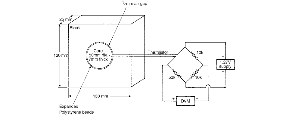
The calorimeter system is shown schematically in
Figure 6.15.
The calorimeter core is a disc of graphite 50 mm in
diameter and 7 mm in thickness. A hole, 1.5 mm in diam-
eter and 7 mm deep, is drilled radially into the mid-plane
FIGURE 6.14 The schematic configuration of the gaps in the ENEA graphite calorimeter. The gaps around the calorimeter core, c,
are those denoted 1–3. Gap 4 is between the calorimeter and the frontal external plate,
p, used to vary the measurement depth. The
gap width is 0.5 mm for all of the anterior gaps and for the annular gaps 1 and 2, 1 mm for the annular gap 3, and 0.65 mm and
1.2 mm for the posterior gaps 1 and 2, respectively. (From Reference [12]. With permission.)
D
g
P
w
() QP
w
()N
g
D
g
P
w
()
g
P
w
()
en
()
g
g
D
w
P
w
()
w
P
w
()
en
()
w
w
D
w
P
w
() D
g
P
w
()
en
()
w
en
()
g
[]
w
g
()
m
g
(6.18)
D
w
P
w
() QP
w
()N
g
en
()
g
w
g
w
g
w
x
b
a
CH-06.fm Page 341 Friday, November 10, 2000 12:02 PM
342 Radiation Dosimetry: Instrumentation and Methods
of the core to accommodate a glass bead thermistor with a
nominal resistance of 50 k at 20°C. Thermal contact with
the graphite is improved by using a small amount of zinc
oxide–based heat sink compound around the thermistor
bead. This disc is inset into the surface of a rectangular
block of graphite approximately 130 130 25 mm
deep and is thermally isolated from the block by a nominal
0.5-mm air gap. Small expanded polystyrene beads sepa-
rate the disc from the block. The dimensions of the block
were chosen to be sufficiently large to ensure the complete
scattering of 15-MeV electrons into the core, but at the
same time they are small enough to give relatively uniform
heating of the rectangular block, in area and in depth, in
a scattered electron beam from the NPL linear accelerator
(linac). The core and surrounding block are completely
enclosed in 25 mm of expanded polystyrene, which has
been shown to have no measurable effect on the response
of the calorimeter. If this assembly is allowed to reach
equilibrium in an environment which is temperature con-
trolled to
200 mK, any temperature drift of the core is
linear over a period of tens of minutes and is always less
than 0.5 mK/min. Dose rates down to about 3 Gy/min,
and doses below 1 Gy, have been measured without the
need for further temperature control. In particular, no vac-
uum system or controlling heaters are necessary. [13]
A description was given by DuSautoy [14] of the UK
primary standard graphite calorimeter system. The calo-
rimeter measures absorbed dose to graphite for photon
radiations from
60
Co to 19-MV x-rays and is the basis of
the NPL therapy-level absorbed dose to water calibration
service. Absorbed dose to graphite from the photon calo-
rimeter has been compared with three other standards: an
ionization chamber and cavity theory, for
60
Co gamma
radiation; the NPL electron calorimeter, for 12–14-MeV
electron beams; and the BIPM
60
Co absorbed dose stan-
dard. The calorimeter has been called the photon-beam
calorimeter to distinguish it from the electron-beam calo-
rimeter. This calorimeter has been the primary standard
for the NPL calibrations in absorbed dose to water and
the chemical dosimetry services since 1988. The mean
absorbed dose to carbon (graphite) in the core of the
calorimeter D
c
is determined by measuring the energy
deposited by ionizing radiation, E
R
, in the core of mass
m, according to the definition of absorbed dose given by
(6.20)
For a dose of 1 Gy, the energy absorbed, E
R
, raises the
temperature of the core by about a millikelvin. This tem-
perature rise is measured with a resolution of a few tens
of microkelvin by a thermistor embedded in the core.
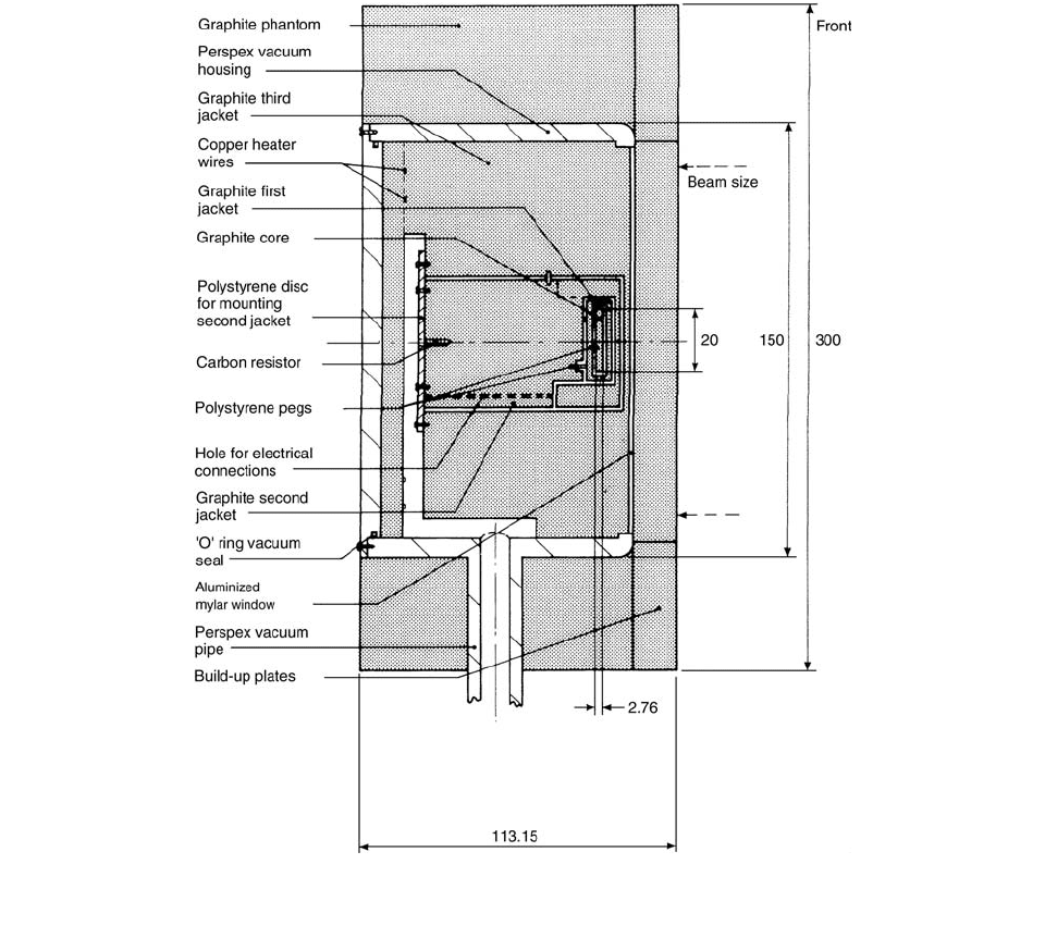
Figure 6.16 shows the vertical cross section through
the axis of the assembled calorimeter and gives the dimen-
sions in more detail. The core is placed near the front so
that electron beam measurements can be made. The min-
imum measurement depth is about 1 g cm
2
. Two ther-
mistors are included in the core; one is used as a sensor
and the other as a heater for the electrical calibration.
The core resistance measurement and heating circuits
are shown in Figure 6.17. Initially the second jacket heat-
ing is regulated to produce a constant second jacket tem-
perature, and the core and first jackets are allowed to reach
thermal equilibrium. The core, first jacket, and second
jacket bridges are then balanced by adjusting the balancing
resistor (e.g., R
M
in the core circuit). Before a measure-
ment, the heating power in the second jacket is fixed at a
FIGURE 6.15 Schematic diagram of calorimeter system. The calorimeter block is completely enclosed in 25 mm of expanded
polystyrene. (From Reference [13]. With permission.)
D
c
E
R
m
------
CH-06.fm Page 342 Friday, November 10, 2000 12:02 PM
Calorimetry 343
level which gives steady increase in temperature at a rate
of approximately 12
K min
1
.
Figure 6.18 shows a typical measurement sequence.
The bridge amplifier output voltages of the core and two
jackets are recorded for about 300 seconds (A to B). The
calorimeter is then irradiated (B to E), reducing the resis-
tance of the sensing thermistors embedded in the core and
two jackets and increasing their bridge output voltages.
Irradiations last for about 80 seconds. Midway through
the irradiation time (at C), the switch, S1, is closed, reduc-
ing the resistance of that arm of the core bridge by a small
fixed amount (i.e., 0.1 ). Simultaneously, the balancing
resistances of the first and second jacket bridges are
reduced to offset their bridge output voltages below their
balance points. The irradiation continues to heat the cal-
orimeter, increasing the bridge output voltages. The irra-
diation is stopped (at E) when the core bridge output
voltage returns to the pre-heating balance voltage (at B).
The output voltages of all the bridges then level off and
are recorded for a further 300 s (E to F) after the heating.
The dose the core would have received if it had been
entirely graphite, D
c
, can be calculated from [14] as
(6.21)
where m
g
is the mass of graphite, m
i
is the mass of the non-
graphite impurity identified by the subscript i, n is the num-
ber of non-graphite impurities, D
g
is the average absorbed
dose in graphite, and D
i
is the average absorbed dose in the
impurity labeled i. The ratio of the doses D
i
/D
g
is suffi-
ciently near unity and the impurities are so small for this
calorimeter that the effective mass of the core m was taken
(for all beams and energies) as i.e.,
1.5043 g 0.05%.
FIGURE 6.16 Schematic diagram of the NPL calorimeter. Side-view cross section. Not to scale. Dimensions in mm. (From Reference
[14]. With permission.)
D
c
E
R
m
g
m
i
D
i
D
g
------
i1
n
mm
g
i1
n
m
i
,
CH-06.fm Page 343 Friday, November 10, 2000 12:02 PM
344 Radiation Dosimetry: Instrumentation and Methods
IV. OTHER MATERIAL CALORIMETERS
The thermal defects of A-150 plastic and graphite refer-
enced to aluminum were determined by Schulz et al. [15]
for 800-keV protons scattered by a 2-
m nickel foil (mean
transmitted energy 550 keV). Composite cores of A1/
A-150, graphite/A-150, and Al/graphite which could be
irradiated from one side or the other were employed. The
temperature increase of a core caused by 30–100 s of
irradiation (3–6 nA of proton beam current) was detected
by two thermistors mounted in opposite legs of a Wheat-
stone bridge. The thermal defect of A-150 plastic was
determined to be 0.0421 0.0036 (SE) referenced to
aluminum and 0.0402 0.0034 referenced to graphite.
The thermal defect of graphite referenced to aluminum is
0.0043 0.0034. No change in the thermal defect of
A-150 plastic was detected for accumulated doses up to
8 Gy.
FIGURE 6.17 Schematic diagram of electrical circuits. (From Reference [14]. With permission.)
FIGURE 6.18 Plot of bridge output voltage against time. (From Reference [14]. With permission.)
10
5
CH-06.fm Page 344 Friday, November 10, 2000 12:02 PM
Calorimetry 345
A key consideration in the application of tissue-
equivalent materials, solids, or liquids to absorbed-dose
calorimeters is the extent to which energy absorbed from
ionizing radiations is converted to heat. Specifically, the
thermal defect of a material is defined as the expected
temperature change minus the observed temperature
change, the difference then divided by the expected tem-
perature change; positive thermal defects indicate endo-
thermicity, while negative thermal defects indicate exo-
thermicity. [15]
A flat, cylindrical absorber (the core), one side of
which is the reference material, is mounted so that it can
be rotated through 180° (about a diameter passing through
its mid-thickness) and irradiated from one side or the
other. As the temperature rise caused by irradiation
depends on the heat capacity of the composite core, a
temperature rise caused by irradiation of the test material
which differs from that for the reference materials is indic-
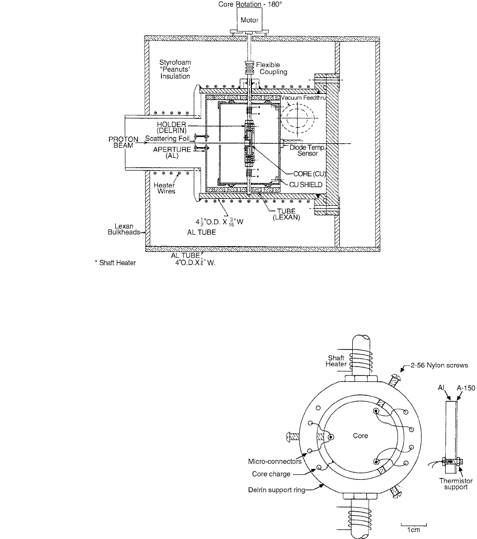
ative of a thermal defect. A cross-sectional drawing of the
thermal-defect calorimeter is shown in Figure 6.19, and a
more detailed drawing of the core support and A-150/
aluminum core is shown in Figure 6.20. Each core has
three holes in its periphery to accept three thermistors,
two of which were connected to opposite legs of a Wheat-
stone bridge and the third used as an ohmic heater for
system testing. Because the thermal diffusivity of A-150
plastic (2.7 10
3
cm
2
s
1
) is much lower than aluminum
(4.1 cm
2
s
1
) or graphite (4.6 cm
2
s
1
), the A-150 absorber
was made about 0.4 mm thick.
The core assembly was surrounded by an insulated cop-
per shield which is connected in series to an electrometer
and a high-voltage power supply. With this arrangement,
FIGURE 6.19 The thermal-defect calorimeter. Vacuum on the order of 10
3
Pa is provided by the accelerator beam-line diffusion
pump. The proton valve/beam-centering device is mounted directly to the left side of the calorimeter as shown above. (From
Reference [15]. With permission.)
FIGURE 6.20 The A-150 plastic/aluminum core and the core
support assembly. (From Reference [15]. With permission.)
CH-06.fm Page 345 Friday, November 10, 2000 12:02 PM
346 Radiation Dosimetry: Instrumentation and Methods
the bias applied to the shield can be varied between 500 V
and the shield charge recorded. The entire calorimeter is
maintained at 300 K by electrical heating wires wrapped
around its body. The calorimeter is suspended at the center
of a 25-cm OD aluminum tube.
The thermal defect was calculated from
(6.22)
where
d is the chart recorder deflection and Q is the sum
of core and shield charges.
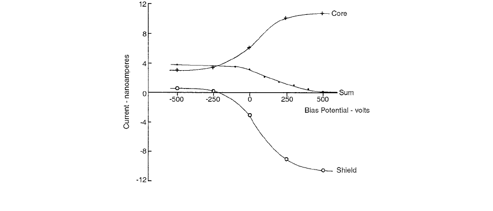
The effect of shield bias potential on the charge
collected from the core and shield was tested with the
aluminum/graphite core, and the results for aluminum
using potentials in the range
500 V are shown in
Figure 6.21. Data similar to those shown in Figure 6.21
were also measured for graphite and, although different
values for the sums of core and shield charges were
obtained for zero and positive shield bias, essentially
the same values as for aluminum were obtained when
the shield was negative. All of the thermal-defect data
reported below were obtained with negative 500 V
applied to the shield.
An experimental setup was described by Brede et al.
[16] which allows the calorimetric determination of the
heat defect of solids and fluids relative to that of gilded
copper, which was used as the reference material. The
calorimeter operated in a quasi-adiabatic mode and was
suitable for protons, deuterons,
particles, and other
heavy ions with energies above 5 MeV. Corrections have
been made for secondary electron emission and also for
heat losses due to the temperature gradient on the surface
of the calorimeter core.
The heat defect,
h, describes that fraction of the absorbed
energy which does not result in a temperature change of the
absorber. It is defined by the equation
(6.23)
where
W
a
represents the energy absorbed and W
h
is the
energy that appears as heat.
In mixed neutron-photon fields, the absorbed dose to
water is generated by secondary electrons and charged
particles such as protons, deuterons,
particles, and recoil
oxygen nuclei. The various particles produce markedly
different ionization densities along their tracks, and this
can be described by their linear energy transfer, LET.
Knowledge of the LET dependence of the heat defect in
water is therefore a prerequisite for the water calorimeter,
in order to reduce the main component of the uncertainty
in water calorimetry and to apply a correction factor in
mixed neutron-photon fields.
The material under investigation—in this case A-150
plastic or water—was contained in a cylindrical canister
of gilded copper with an inner diameter of 15 mm and a
length of 5 mm and which has an eccentric beam stop (see
Figure 6.22). Two different A-150 plastic absorbers from
different production lots were investigated. All samples
had the same geometrical dimensions—a cylindrically
shaped probe, 3.5 mm in thickness and 15 mm in diameter.
They were pressed into the canister. A 7-
m-thick indium-
sealed molybdenum entrance window allowed charged
particles to enter the core.
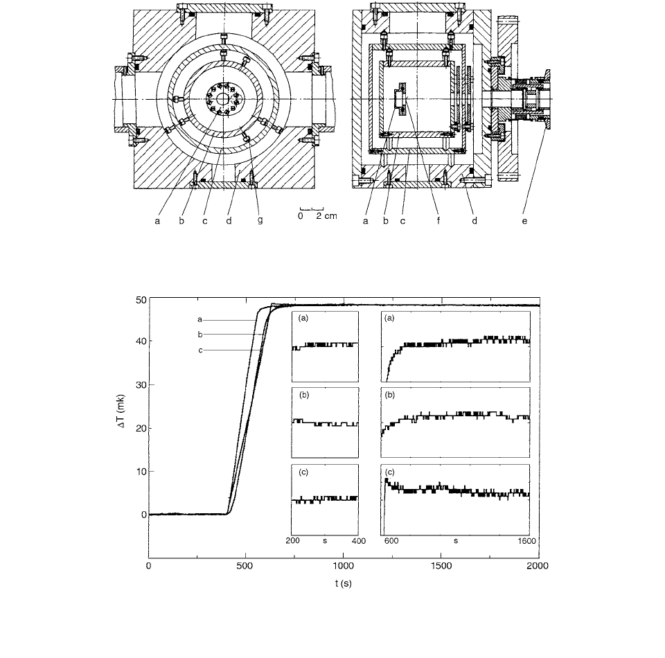
The calorimeter (Figure 6.22) comprised a core, inner
and outer jacket, and vacuum chamber which were ther-
mally and electrically insulated from one another and
operated in an adiabatic mode. The temperature increase,
T
i
, (i indicates either A-150 or water) measured on the
FIGURE 6.21 The effect of shield bias on the current collected by the core and shield. (From Reference [15]. With permission.)
d Q
ref
d Q
test
()
dQ
ref
------------------------------------------
hW
a
W
h
()
W
a
CH-06.fm Page 346 Friday, November 10, 2000 12:02 PM
Calorimetry 347
core surface is given by
(6.24)
where
C is the total heat capacity of the calorimeter
core, h
i
is the heat defect in either A-150 plastic or
water, Q
b
is the total beam charge deposited in the core,
and U
b
is the voltage which is used to accelerate the
particles; i.e., the product Q
b
U
b
is the total energy
imparted in the absorber.
The temperature measurements of the core and
jackets were made with cylindrically shaped ther-
mistors (NTC) 0.35 mm in diameter and 0.5 mm in
length (type 6331 from Philips) and were connected to
thin copper wires 0.06 mm in diameter and 30 cm in
length.
The calorimetric measurement started with an analysis
of the initial drift for about 400 s. After an irradiation time
of 200 s, the system equilibrated during a time of approx-
imately 500 s. During the next 500 s, the final temperature
drift was recorded (see Figure 6.23). The temperature
increase was determined from the linear region of the
initial and final drifts and was normalized to the beam
charge collected from the core. The measurements were
carried out alternately with gilded copper and water or A-
150 plastic as the beam stop. The quantity (
T
i
T
m
) was
determined from sequential measurements in order to
reduce systematic errors. [16]
FIGURE 6.22 Core (a); inner jacket (b); outer jacket (c); vacuum chamber (d); flange connection to the beam line (e); entrance
window (f); and screws (g) to align the core with nylon cords (not shown). (From Reference [16]. With permission.)
FIGURE 6.23 Time (t) plotted against temperature (T) response of the calorimeter. Beam stop: A-150 plastic (a), water (b), and
gilded copper (c). The inserts on the left-hand side show the initial temperature drifts; the inserts on the right-hand side show the
response after the end of irradiation. The temperature scale of all inserts is 2 mK. (From Reference [16]. With permission.)
T
i
C 1 h
i
()
1
Q
b
U
b
CH-06.fm Page 347 Friday, November 10, 2000 12:02 PM
348 Radiation Dosimetry: Instrumentation and Methods
REFERENCES
1. Domen, S. R., J. Res., NBS 87, 211, 1982.
2.
Ross, C. K. and Klassen, N. V., Phys. Med. Biol., 41,
1, 1996.
3.
Fleming, D. M. and Glass, W. A., Rad. Res., 37, 316,
1969.
4.
Selbach, H. J. et al., Metrologia, 24, 341, 1993.
5.
Ross et al., Metrologia, 29, 59, 1992.
6.
Schulz, R. J. et al., Med. Phys., 14, 790, 1987.
7.
Domen, S. R., J. Res. Natl. Inst. Stand. Tech., 99, 121,
1994.
8.
Schulz, R. J. et al., Med. Phys., 18, 1229, 1991.
9.
Seuntjens, J. et al., Phys. Med. Biol., 38, 805, 1993.
10.
Palmans, H. et al., Med. Phys., 23, 643, 1996.
11.
Palmans, H. et al., Phys. Med. Biol., 44, 647, 1999.
12.
Guerra, A. S. et al., Phys. Med. Biol., 41, 657, 1996.
13.
Burns, D. T. and Morris, W. T., in Proc. High Dose
Dosimetry for Radiation Protection,
IAEA, 1991, 123.
14.
DuSautoy, A. R., Phys. Med. Biol., 41, 137, 1996.
15.
Schulz, R. J. et al., Phys. Med. Biol., 35, 1563, 1990.
16.
Brede, H. J. et al., Rad. Prot. Dos., 70, 505, 1997.
17.
ICRU49, stopping powers and ranges for protons and
alpha particles, 1973.
CH-06.fm Page 348 Friday, November 10, 2000 12:02 PM
349
7
Chemical Dosimetry
CONTENTS
References .......................................................................................................................................................................359
The major advancement of the last decade in chemical
dosimetry is the development of the gel dosimeter. This
is actually an application of a physical phenomenon for
better utilization of the well-known Fricke dosimeter. The
present chapter mentions in brief some of the contributions
made to the use of the already known chemical dosimeters.
Chapter 9 is devoted to gel dosimetry.
When dose is measured in water irradiated by an elec-
tron beam, the absorbed dose measured with the plane-
parallel chamber in the polystyrene phantom can be cor-
rected to obtain the dose to water, according to the equation
(7.1)
where the depth in water
d
water
is related to the depth in the
medium
d
med
by
(7.2)
where is the ratio of the mean unrestricted mass
collision stopping power in water to that in the medium;
is the fluence factor, i.e., the ratio of electron fluence
in water to that in the solid phantom;
R
50
is the depth of the
50% ionization; and
P
eff
is the effective density of the
medium and is discussed in the AAPM TG 25 protocol,
where recommended values of
P
eff
and are given.
An independent method of absolute dosimetry is the
use of the ferrous sulphate dosimeter. The Fricke solution
can be prepared by combining 1 mmol/l ferrous ammo-
nium sulphate with 1 mmol/l sodium chloride and 0.4 mol/l
sulfuric acid in double distilled water. [1] When the solu-
tion is irradiated, the ferrous ions Fe
2
are oxidized by
radiation to ferric ions Fe
3
. The oxidation of the ferrous
ions is directly proportional to the absorbed dose. The
ferric-ion concentration can be measured by the change
in the absorbance using a spectrometer.
The absorbed dose to the dosimeter solution,
D
fricke
,
can be calculated according to the equation
(7.3)
where
A
t
is the increase in the absorbance due to irradia-
tion at a temperature
t
during the spectrophotometric mea-
surement;
is the density of the Fricke solution (
1.024
10
3
/kg/ );
l
is the length of the light path in the
photometer cell (
l
is generally 0.01 m);
mt
is the molar
absorption coefficient for the ferric ions at temperature
t
;
and is the radiation chemical yield of ferric ions at the
irradiation temperature . For all the electron beam ener-
gies, an
m
G
value of 352
k G was
adopted from ICRU Report No. 35 [9] at an irradiation
temperature of 25°C and a spectrophotometer measure-
ment temperature
t
of 25°C. A correction for the temper-
ature
t
differing from 25°C was made according to the
equation
(7.4)
where the temperature coefficient
k
1
, is approximately
0.0007° and is 0.0015° . Using the mass stop-
ping power ratio
S
W,Fricke
to convert the dose to
the ferrous sulphate solution,
D
Fricke
, to the dose to water,
D
water
, Equation 7.3 becomes
(7.5)
The ratios of the values of the absorbed dose to water
determined with the Exradin chamber, calibrated using all
three different calibration methods and the Fricke dosim-
etry, as a function of the mean energy at depth,
E
z
, are
shown in Figure 7.1.
As mentioned above, gel dosimetry is discussed in
Chapter 9. Because of the strong affiliation of that technique
to chemical dosimetry, an example is given here. The
nuclear magnetic resonance (NMR) longitudinal relaxation
D
water
d
water
()D
med
d
med
()S
[]
med
water
med
water
d
water
d
med
eff
d
med
R
50
water
R
50
mef
()
S/
()[]
med
water
med
water
med
water
D
fricke
A
t
l
mt
G
t
------------------------
m
3
G
t
t
10
6
m
2
g
1
y
1
t
mt
G
t
m25C
G
25C
1 k
1
25 t()[]
1k
2
25 t()[]
C
1
k
2
C
1
1.004
D
water
A
t
l
mt
G
t
--------------------
278.54A
t
1 0.007 25 t()[]1 0.0015 25 t()[]
----------------------------------------------------------------------------------------------------------
CH-07.fm Page 349 Friday, November 10, 2000 12:03 PM