Satas D., Tracton A.A. (ed.). Coatings Technology Handbook
Подождите немного. Документ загружается.


162
BREBNER
ALIBRATED SPRING
TEST STRUCTURE
Figure
6
Hot tack spring test.
9%
ACID IONOMER
-
"""_
#.-e
-"
-.
1
200
220
240
i
SEAL INTERFACE TEMPERATURE,
"F
-.
-.
0
Figure
7
Hot strength versus interface temperature
(1
mil
coatings
on
30
lb.
kraft paper).

EXTRUSION COATING WITH ACID COPOLYMERS AND IONOMERS
163
nonpolar material, has very low hot tack strength. The acid functionality
of
the copolymers
results in much higher hot tack strength because of interchain hydrogen bonding. The
combination of hydrogen bonding and ionic bonding in the ionomers produces an even
greater maximum hot tack strength and a broader hot tack range. In practice, this means
that the ionomers will tolerate the broadest range of sealing conditions and offer the highest
speeds
on
packaging lines.
3.0
PROCESSING CONDITIONS
3.1
Melt Temperatures
Low density polyethylene is typically processed at melt temperatures in the range of
600-630°F. These high temperatures are necessary to promote surface oxidation
of
the
resin and to ensure adequate adhesion to the substrate. However, it is not necessary to
oxidize the acid copolymers
or
ionomers, since the acid functionality
is
responsible for
adhesion to either foil or paper. These resins should be processed at the lowest melt
temperature consistent with adequate product performance. One obvious reason to prefer
a lower melt temperature is to reduce the chance of odor
or
taste problems in packaging
sensitive products. Another reason is shown in Figure
8.
Both the acid copolymers and
ionomers can undergo a process called anhydride cross-linking, in which carboxyl groups
in adjoining molecules react to form an anhydride cross-link and produce water as by-
product. This reaction occurs at a significant rate in the temperature range at which the
copolymers and ionomers are normally processed. The cross-linking reaction causes gel
formation, while the water causes die buildup problems.
As
approximate guidelines, the
C
-
OH
0
II
C-
l1
0
+
0-
0
0
Figure
8
Anhydride cross-linking.

164
BREBNER
Table
2
Product
~ ~~
Melt temperature
(F)
High acid, high melt index
450-500
Intermediate acid
and
melt index
500-550
Low
acid and melt index
550-590
melt temperatures shown in Table
2
are recommended for acid copolymers and ionomers,
assuming that desired product properties can be achieved under these conditions.
3.2 Other Considerations
Both the acid copolymers and ionomers are slightly corrosive,
so
that metal parts exposed
to
these products at high temperature should be plated with nickel or chrome. Another
factor to be considered is the moisture sensitivity
of
the ionomers. The ionomers are
hygroscopic and as
a
consequence are packaged
in
foil-lined bags and boxes. When a box
is
opened, only
a
comer of the liner should be cut
off
to permit insertion of the transfer
pipe. If this is done properly, it is easy
to
reseal the liner of
a
partially
used
box by folding
it over and taping securely. With normal precautions, the moisture sensitivity of ionomers
does not present an operational problem.

18
Porous
Roll
Coater
1
.O
INTRODUCTION
Recent progress had been made in silicone-coated products that are curable by electron
beam
(EB)
and ultra violet (UV). Advantages of UV and
EB
converting processes are
shown in Figure
1.
Of these new products, in which the release levels range between 25
and
50
g
per
25
mm wide strip, typical viscosities
of
the materials tested are in the range
of
500-
1000
cp at room temperature. These silicone products are manufactured by Th.
Goldschmidt, in West Germany, and Lord Corporation, in Pennsylvania, and other compa-
nies. The UV products are either one-part premixedlready-to-use materials, or two-compo-
nent products that require nitrogen inerting to overcome surface smear and to achieve a
complete cure at web speeds up to
30
dmin per each UV lamp. A schematic diagram of
nitrogen inerting process is shown in Figure 2. The UV lamps used for curing are rated
at
300
W/in.
(
120 W/cm per lamp). The
EB
products are also premixedlready-to-use, and
as with the UV chemistries also require nitrogen inerting to obtain
a
full cure at typical
web speeds
of
200
dmin. The energy dosage is approximately 2 megarads (Mrad). A
schematic diagram of an
EB
processor is shown in Figure
3.
2.0
EXTRUSION POROUS ROLL SYSTEM
2.1
Development
One recently developed extrusion roll coating system incorporates
a
slot nozzle coating
head, located adjacent to a slow speed “nozzle roll” (see Fig.
4).
The fluid is coated onto
the “nozzle roll” and transferred
to
an adjacent “applicating roll,” which in turn contacts
the coating web for fluid transfer. The relative speed ratio between the “nozzle roll” and
the “applicating roll”
is
approximately
1:30.
Reports on trials have noted that the curable coatings possess poor shear properties
and that the speed ratio between the rolls is somewhat dependent on this limitation. The
165

166
MCINTYRE
NONPOLLUTING
MORE EFFICIENT (LESS ENERGY REQUIRED)
CAN BE USED ON BOTH FILMS AND PAPERS
NON THERMAL CURE, ALLOWS MACHINE STOP
R
START
WITH MINIMAL PRODUCT LOSS
MULTIPLE PROCESS PERMITS SILICONE IN-LINE WITH
HOT MELT PRODUCTS
LOW HEAT ENERGY ALLOWS COATING OF THERMAL
SENSITIVE WEB MATERIALS
FULL CURE PROCESS MINIMIZES SILICONE MIGRATION
AND CONTAMINATION
Figure
1
Advantages
of
radiation curing.
Figure
2
UV
irradiation with nitrogen inerting

POROUS
ROLL
COATER
CHAMBER
STRUCTURE TERMINAL
ELECTRON GUN
/
FILAMENT
Figure
3
EB
process.
PUMP
‘DIGITAL
MOTOR
DRIVE
Figure
4
Roll
coater
with
extrusion
feed.
167

168
MCINTYRE
I
PUMP HOLDING
BACK
R
OL
ING
.L
\
FLUID
FLUID
TROUGH
TRANSFER
ROLL
GRAVURE
ROLL
/
METERING
ROLL
Figure
5
Transfer
roll
coater.
shear properties can be improved by heating the rolls, but this method is not always
productive, with the result that the coated web has the appearance
of
small blotches,
1-2
mm or larger, or lateral bands (chatter)
of
coating, rather than
a
smooth, uniform coating.
Likewise, conventional roll coaters, which contain multiple rolls, experience
a
similar
effect (see Fig.
5).
This phenomenon is associated with fluids that have poor flow properties
and dilatant characteristics. Viscosity of dilatant fluids increases with increasing shear rate
as shown
in
Figure
6.
The actual coat weight applied in either case is influenced by the
web substrate material, surface conditions. silicone product properties, and the method of
applications.
SHEAR RATE
Figure
6
Viscosity dependence
on
shear rate
of
a
dilatant fluid.
POROUS
ROLL COATER
169
RETURNFEED
l
POSITIVE ROTARY UNION
DISPLACEMENT
METERING PUMP
DIGITAL
PUMP DRIVE
3-WAY VALVE
/
/
LAMINATING
ROLL
WEB REFERENCE PICKUP
TO SYNCHRONIZE PUMP
APPLlCATl NG ROLL
SPEED TO WEB SPEED
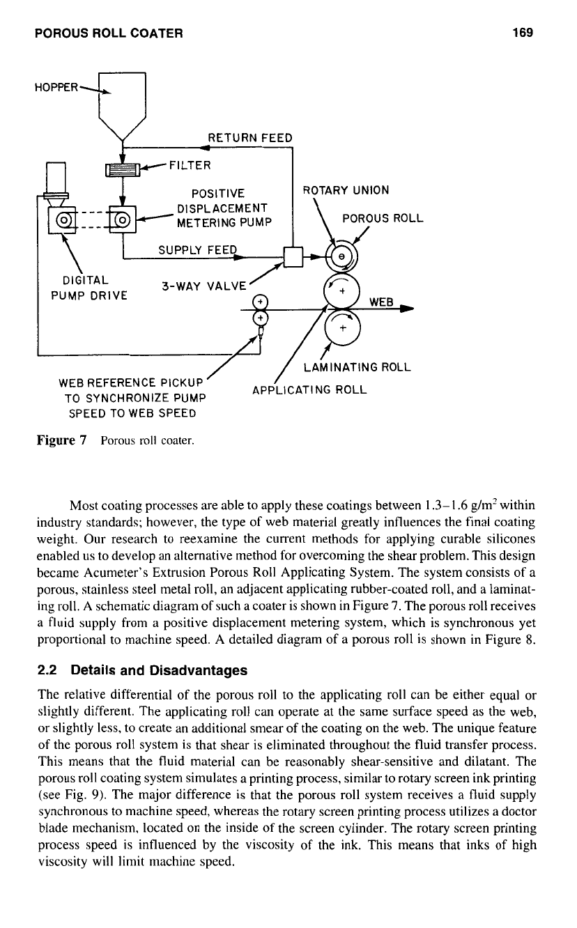
Figure
7
Porous
roll
coater.
Most coating processes are able to apply these coatings between
1.3-1.6
g/m’ within
industry standards; however, the type
of
web material greatly influences the final coating
weight. Our research to reexamine the current methods for applying curable silicones
enabled us to develop an alternative method for overcoming the shear problem. This design
became Acumeter’s Extrusion Porous
Roll
Applicating System. The system consists of a
porous, stainless steel metal roll, an adjacent applicating rubber-coated roll, and
a
laminat-
ing roll. A schematic diagram of such
a
coater is shown in Figure
7.
The porous roll receives
a
fluid supply from
a
positive displacement metering system, which is synchronous yet
proportional to machine speed. A detailed diagram of a porous roll is shown in Figure
8.
2.2
Details and Disadvantages
The relative differential of the porous roll to the applicating roll can be either equal or
slightly different. The applicating roll can operate at the same surface speed
as
the web,
or
slightly less, to create an additional smear of the coating on the web. The unique feature
of the porous roll system is that shear is eliminated throughout the fluid transfer process.
This means that the fluid material can be reasonably shear-sensitive and dilatant. The
porous roll coating system simulates
a
printing process, similar to rotary screen ink printing
(see Fig.
9).
The major difference is that the porous roll system receives
a
fluid supply
synchronous to machine speed, whereas the rotary screen printing process utilizes
a
doctor
blade mechanism, located on the inside of the screen cylinder. The rotary screen printing
process speed is influenced by the viscosity
of
the ink. This means that inks of high
viscosity will limit machine speed.

170
MCINTYRE
SINGLE WIDTH
SURFACE PREPARATION
WI
DETERMINES APPLICATION
POROUS STAINLESS STEEL
iICH
PATTERN
/
SINTERED METAL
OUTER
SHELL
SINGLE SUPPLY PORT
AND ROTARY UNION
-~
~
-
.
-
_"
I
INNER SUPPLY ROLL
RESERVOIR CAVITY
Figure
8
Diagram
of
a
porous
roll.
In contrast, the porous roll system with synchronous positive displacement fluid
supply
is
insensitive to viscosity change. The important element is synchronous fluid
metering to obtain consistent and controlled coating weights applied at wide ranges
of
machine speeds.
Manufacturers
of
curable silicones have indicated that higher viscosity materials
are
desirable for obtaining special release levels.
As
mentioned earlier, conventional multiple-
roll coating systems perform best when handling fluids less than
1000
cp. The porous roll
system has been tested with coatings having viscosities to
10.000
cp.
Changing the micrometer openings in the porous roll applicator will permit
handling of higher viscosity materials (see Fig.
10).
For example, coatings
of
polyvinyl
resin emulsion adhesives, having a viscosity
of
5000
cp at a coating thickness
of
approximately
30
pm have been successfully applied without difficulty. Silicone prod-
ucts or other coating materials that have higher viscosities such as
10.000
cp may
require a porous roll having larger openings, depending on flow properties. The larger
PRINTING
FLUID
INK
Figure
9
Rotary
screen
printer.

POROUS
ROLL
COATER
171
STANDARD SHELL POROSITY
GREATER POROSITY SHELL
Figure
10
Porous
roll
applicator porosity.
porous openings will minimize the fluid back pressure and allow for consistent coat
weights at various machine speeds.
The porous roll surface can
be
sealed for printing
of
fluids in patterns, as shown in
Figure
1 1.
This means that special coating patterns required in flexible packaging products,
business
forms,
envelopes, tapes, and labels can utilize curable silicone coatings in the
final converting process, rather than having pre-silicone-printed web materials.
SINGLE WIDTH
MULTIPLE WIDTH
Figure
11
Pattern printing
with
porous roll.