Satas D., Tracton A.A. (ed.). Coatings Technology Handbook
Подождите немного. Документ загружается.

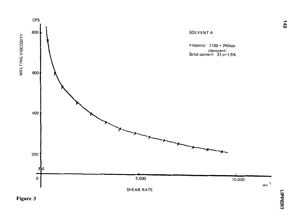
CPS
SOLVENT
A
Viscosity: 1100
+
250cps
Solid
content:
37.0+1.5%
(Ambient)
I
~0,000
5,000
S&’
SHEAR RATE
1
m
-u
-u
3J
-I
SLOT DIE COATING FOR LOW VISCOSITY FLUIDS
143
To adequately adjust these flow variations, a flexible lip is required as a fine-tune adjust-
ment.
Having multiple entrances or a pump within a die simply represents attempts at
producing uniform distribution, minimizing the effect of transverse pressure drop, and
simplifying the job of manifold design.
While a multiple-entrance design attempts
to
minimize the problem of flow distribu-
tion, it actually complicates it by introducing two pressure drops for every entrance in-
stalled. This can cause steps in the coating thickness, and with high viscosity fluids, parting
lines, or “zippers,” in the coating.
Pumping devices built into the die can improve flow distribution
on
simple T-slot
manifold dies; however, they have some inherent disadvantages. Because of their complex
design, streamlined flow and self-purging are compromised. With gear pumps built into
a die, high shear causes a breakdown of some adhesives. The real question is, Why make
tooling more complicated than necessary?
3.0
AIR ENTRAPMENT
Precautions
to
avoid air entrapment in the entire system must be considered carefully.
Complicated piping runs or die manifolds will entrap air, resulting in excessive start-up
times before complete purging
is
accomplished. It is also important to eliminate any point
at which air can be induced into the system. We point out that a pan that is open to
atmospheric pressure
5
placed just before the die manifold, such as
on
a gear pump die,
can create air bubbles
in
the coating.
4.0
LIP
DESIGN
4.1
Lip
Adjustment Design
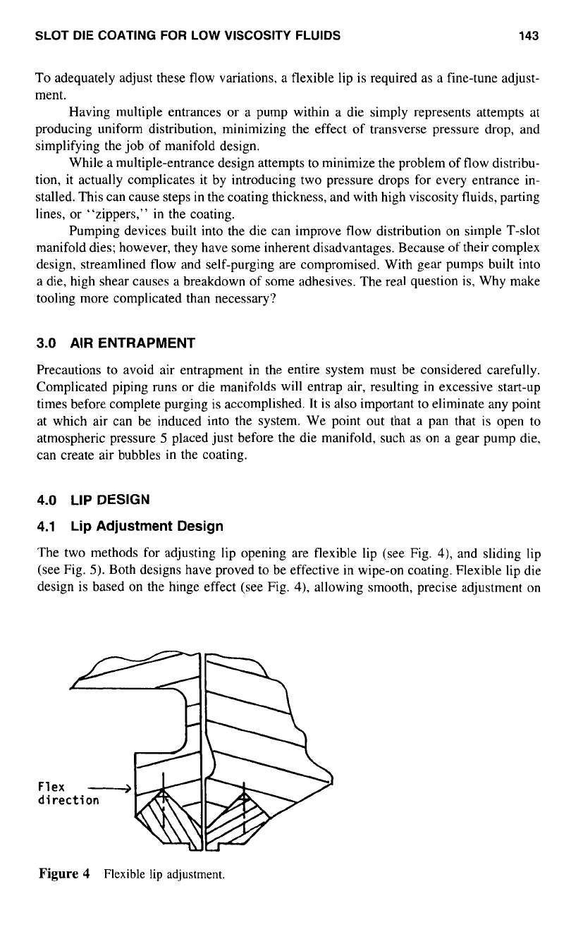
The two methods for adjusting lip opening are flexible lip (see Fig.
41,
and sliding lip
(see Fig.
5).
Both designs have proved to be effective in wipe-on coating. Flexible lip die
design is based on the hinge effect (see Fig.
4),
allowing smooth, precise adjustment on
Flex
->
Figure
4
Flexible
lip
adjustment.
1
44
LIPPERT
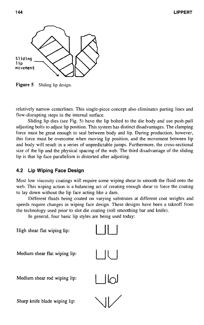
Figure
5
Sliding lip design.
relatively narrow centerlines. This single-piece concept
also
eliminates parting lines and
flow-disrupting steps in the internal surface.
Sliding lip dies (see Fig.
5)
have the lip bolted to the die body and use push-pull
adjusting bolts to adjust lip position. This system has distinct disadvantages. The clamping
force must be great enough
to
seal between body and lip. During production, however,
this force must be overcome when moving lip position, and the movement between lip
and body will result in
a
series of unpredictable jumps. Furthermore, the cross-sectional
size of the lip and the physical spacing of the web. The third disadvantage
of
the sliding
lip is that lip face parallelism is distorted after adjusting.
4.2
Lip Wiping Face Design
Most low viscosity coatings will require some wiping shear to smooth the fluid onto the
web. This wiping action is
a
balancing act
of
creating enough shear
to
force the coating
to
lay down without the lip face acting like
a
dam.
Different fluids being coated on varying substrates at different coat weights and
speeds require changes
in
wiping face design. These designs have been
a
takeoff from
the technology used prior to slot die coating (roll smoothing bar and knife).
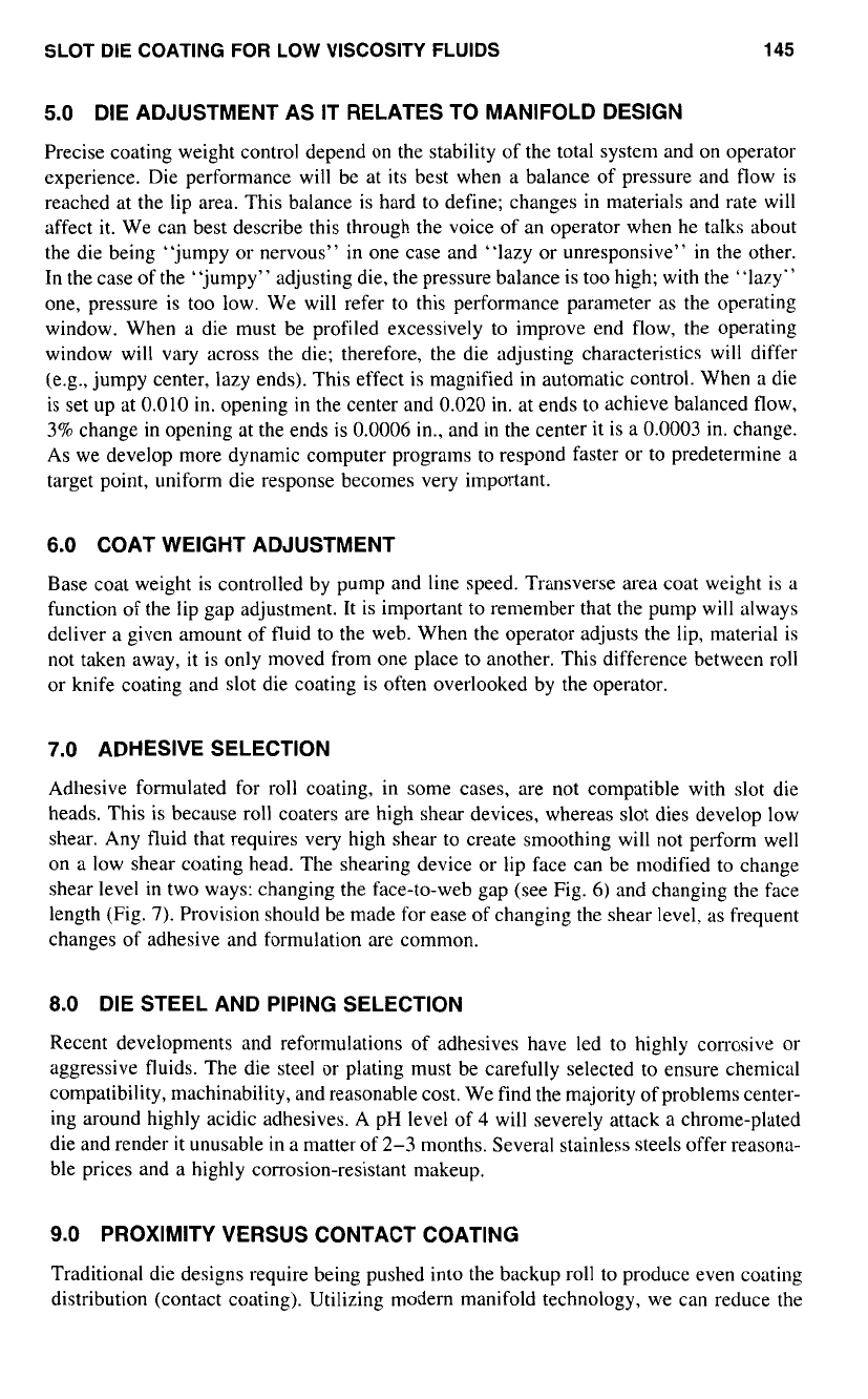
In
general, four basic lip styles are being used today:
High shear flat wiping lip:
uu
Medium shear flat wiping lip:
uu
Medium
shear
rod
wiping lip:
UU
Sharp knife blade wiping lip:
SLOT
DIE
COATING
FOR
LOW
VISCOSITY
FLUIDS
145
5.0
DIE ADJUSTMENT AS IT RELATES TO MANIFOLD DESIGN
Precise coating weight control depend on the stability of the total system and on operator
experience. Die performance will be at its best when a balance
of
pressure and flow is
reached at the lip area. This balance is hard
to
define; changes
in
materials and rate will
affect it. We can best describe this through the voice of an operator when he talks about
the die being “jumpy or nervous” in one case and “lazy or unresponsive”
in
the other.
In the case
of
the “jumpy” adjusting die, the pressure balance is too high; with the “lazy”
one, pressure is too low. We will refer to this performance parameter as the operating
window. When
a
die must be profiled excessively to improve end flow, the operating
window will vary across the die; therefore, the die adjusting characteristics will differ
(e.g., jumpy center, lazy ends). This effect is magnified in automatic control. When a die
is set up at
0.010
in. opening in the center and
0.020
in. at ends to achieve balanced flow,
3%
change
in
opening at the ends is
0.0006
in., and in the center it is a
0.0003
in. change.
As we develop more dynamic computer programs to respond faster or to predetermine a
target point, uniform die response becomes very important.
6.0
COAT WEIGHT ADJUSTMENT
Base coat weight is controlled by pump and line speed. Transverse area coat weight is
a
function of the lip gap adjustment. It is important
to
remember that the pump will always
deliver
a
given amount
of
fluid to the web. When the operator adjusts the lip, material is
not taken away, it is only moved from one place
to
another. This difference between roll
or knife coating and slot die coating is often overlooked by the operator.
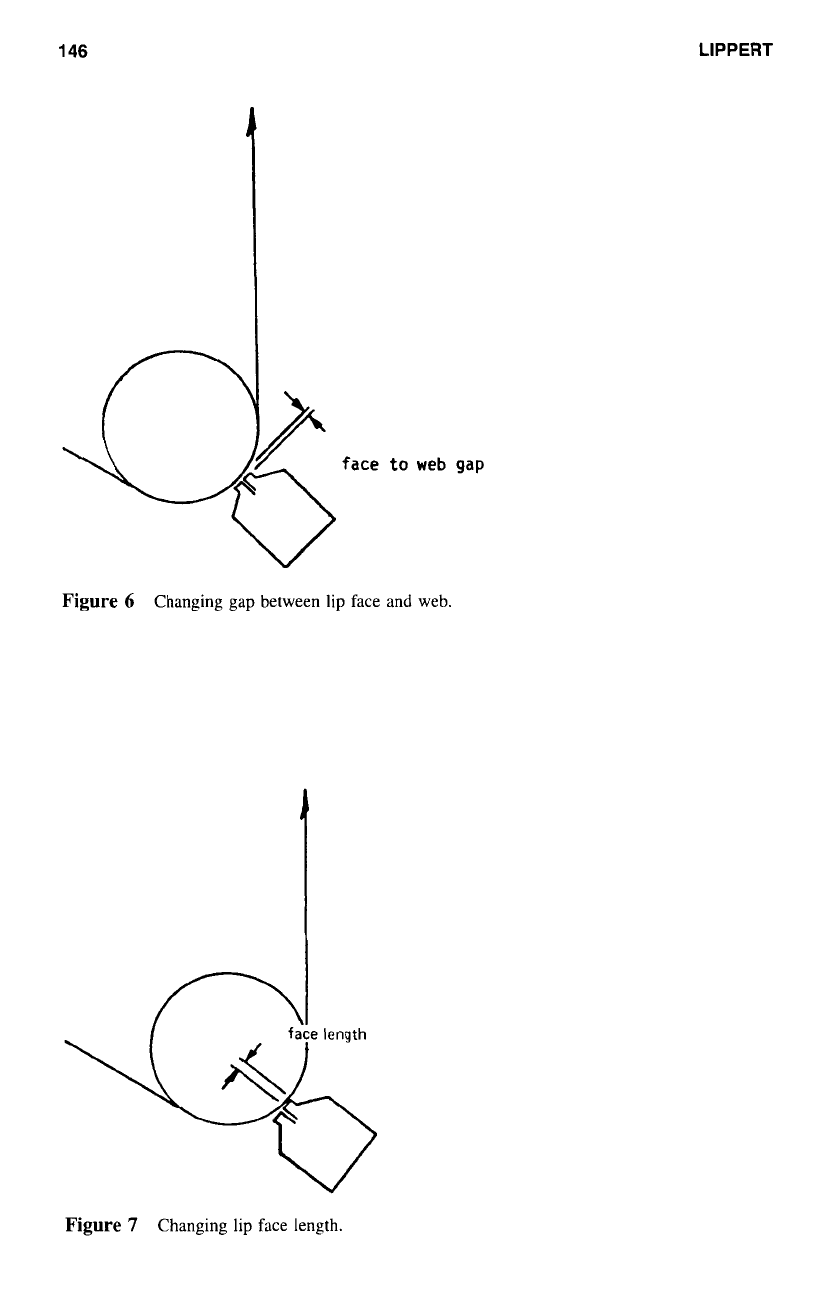
7.0
ADHESIVE SELECTION
Adhesive formulated for roll coating, in some cases, are not compatible with slot die
heads. This is because roll coaters are high shear devices, whereas slot dies develop low
shear. Any fluid that requires very high shear to create smoothing will not perform well
on a low shear coating head. The shearing device or lip face can be modified to change
shear level in two ways: changing the face-to-web gap (see Fig.
6)
and changing the face
length (Fig.
7).
Provision should be made for ease
of
changing the shear level. as frequent
changes of adhesive and formulation are common.
8.0
DIE STEEL AND PIPING SELECTION
Recent developments and reformulations of adhesives have led to highly corrosive or
aggressive fluids. The die steel or plating must be carefully selected to ensure chemical
compatibility, machinability, and reasonable cost. We find the majority of problems center-
ing around highly acidic adhesives.
A
pH level of
4
will severely attack
a
chrome-plated
die and render it unusable in a matter of
2-3
months. Several stainless steels offer reasona-
ble prices and a highly corrosion-resistant makeup.
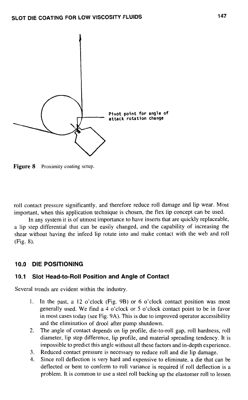
9.0
PROXIMITY VERSUS CONTACT COATING
Traditional die designs require being pushed into the backup roll to produce even coating
distribution (contact coating). Utilizing modern manifold technology, we can reduce the
146
LIPPERT
G)
Figure
6
Changing gap between lip face and web.
l
Figure
7
Changing lip face length.
SLOT DIE COATING
FOR
LOW VISCOSITY FLUIDS
147
Pivot
point
for
angle
of
attack rotation change
Figure
S
Proximity
coating
setup.
roll contact pressure significantly, and therefore reduce roll damage and lip wear. Most
important, when this application technique is chosen, the flex lip concept can be used.
In any system it is of utmost importance to have inserts that are quickly replaceable,
a
lip step differential that can be easily changed, and the capability of increasing the
shear without having the infeed lip rotate into and make contact with the web and roll
(Fig.
8).
10.0
DIE
POSITIONING
10.1
Slot Head-to-Roll Position and Angle
of
Contact
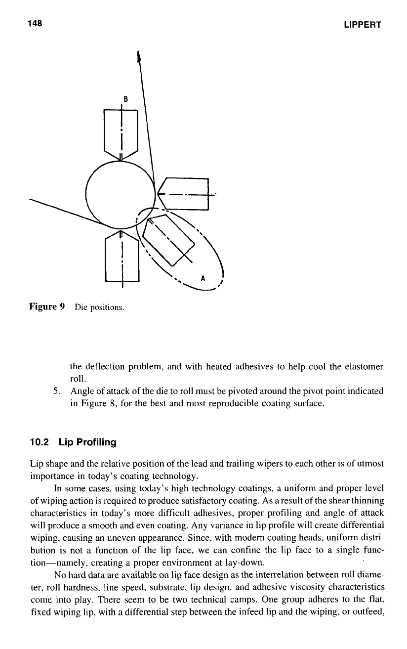
Several trends are evident within the industry.
1.
In the past,
a
12
o’clock (Fig.
9B)
or
6
o’clock contact position was most
generally used. We find
a
4
o’clock or
5
o’clock contact point to be in favor
in most cases today (see Fig. 9A). This is due to improved operator accessibility
and the elimination of drool after pump shutdown.
2.
The angle
of
contact depends on lip profile, die-to-roll gap, roll hardness, roll
diameter, lip step difference, lip profile, and material spreading tendency. It is
impossible to predict this angle without
all
these factors and in-depth experience.
3.
Reduced contact pressure is necessary to reduce roll and die lip damage.
4.
Since roll deflection is very hard and expensive to eliminate,
a
die that can be
deflected or bent to conform to roll variance is required if roll deflection is
a
problem. It is common to use
a
steel roll backing up the elastomer roll to lessen
148
LIPPERT
Figure
9
Die
positions.
the deflection problem, and with heated adhesives
to
help cool the elastomer
roll.
5.
Angle of attack of the die to roll must be pivoted around the pivot point indicated
in
Figure
8,
for the best and most reproducible coating surface.
10.2
Lip
Profiling
Lip shape and the relative position
of
the lead and trailing wipers
to
each other is of utmost
importance in today’s coating technology.
In some cases, using today’s high technology coatings,
a
uniform and proper level
of wiping action is required to produce satisfactory coating. As a result of the shear thinning
characteristics in today’s more difficult adhesives, proper profiling and angle
of
attack
will produce
a
smooth and even coating. Any variance
in
lip profile will create differential
wiping, causing an uneven appearance. Since. with modern coating heads, uniform distri-
bution is not
a
function
of
the lip face, we can confine the lip face to
a
single func-
tion-namely, creating
a
proper environment at lay-down.
No
hard data are available on lip face design as the interrelation between roll diame-
ter. roll hardness, line speed, substrate, lip design, and adhesive viscosity characteristics
come into play. There seem
to
be two technical camps. One group adheres to the flat,
fixed wiping lip, with
a
differential step between the infeed lip and the wiping, or outfeed,
SLOT DIE
COATING FOR
LOW
VISCOSITY
FLUIDS
149
lip. The other group tends to favor a rotating or fixed rod in the wiping area. This rod
style design is as old as die coating, several patents have been issued.
10.3
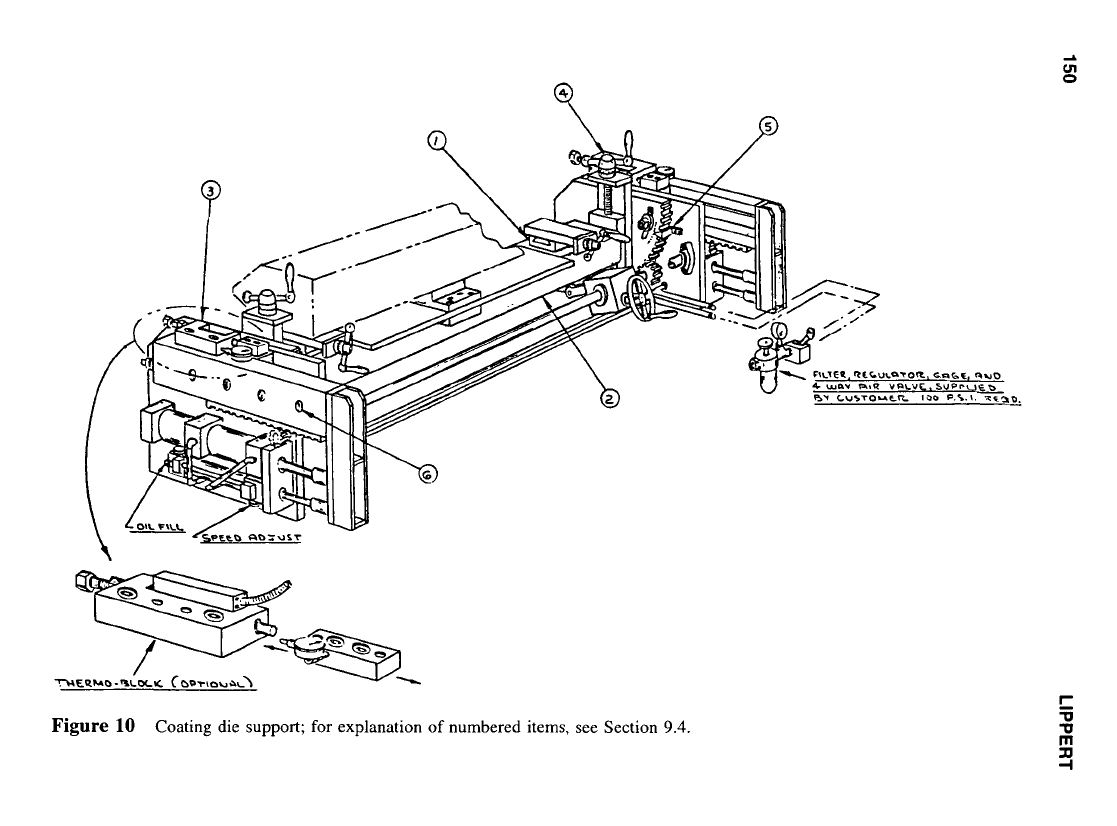
Die Support Design and Operation
The interrelationship of die and mounting require that the two units act as one, both being
equally important. Absolutely necessary to the successful operation of a slot coating head
are the items
in
the series of design specifications indicated
in
Figure
10
and explained
in
Section
9.4.
Application and utilization of existing equipment designs will determine the best
die-to-roll position. Operator convenience and the ability
to
view the point
of
laydown
are very important. It is our opinion that mounting position A in Figure
9
is the most
advantageous, and position
B
the least.
The support bed must be completely rigid and vibration-free. Any sag or bow in
the die will create problems
in
the die-to-roll alignment. For this reason we do not recom-
mend that the die be supported from its ends.
On
heated dies the designer must also allow
for thermal growth while maintaining die straightness.
10.4
Support and Adjustment System Design Specifications
Iter11
I
in Figure
10:
The die should be supported on precision-ground pads, with
die straightness (contouring) adjustments for roll warp correction. On heated dies,
insulation should be provided between die frame, and allowance made for die
growth.
Iten1
2
in
Figure
10:
A heavy-duty rectangular tubing cross frame for maintaining
straightness during operation and adjustment.
Itel71
3
in
Figure
IO:
“X”
in/out adjustment utilizing machine tool slideways with
fast air actuation and hydraulic soft stop cushions. A micro stop correction adjust-
ment with dial indicator or LVDT should be provided for each end.
Iter71
4
irz
Figure
IO:
“Y”
adjustment provided for roll axis position alignment.
Iter11
5
it1
Fi,qure
10:
Angle of attack positioning adjusted through a rack-and-pinion
gear arrangement, with indicator markings
in
degrees. Note that the angle of attack
movement is centered around die lip (coating contact) point.
10.5
Die-to-Roll Positioning
Flexibility and repeatability are primary requirements. Difficult adhesives. speeds, and
substrates will require different setup positions, and the ability to vary the die-to-web
position easily with exact repeatability is
of
prime importance. The support frame must
allow in/out movement and angle of attack adjustment (see Fig.
10).
In/out adjustment will have two functions: (a), fast movement with
5-8
in.
(130-200
mm) of travel, allowing lip cleaning, and (b), micro in/out to fine-tune roll-to-slot gap
distance. This adjustment should allow differential end-to-end gapping.
The in/out adjustment must be on a straight line, always moving directly at the roll
centerline. (Pivot-style mountings are not recommended.)
10.6
Angle of Attack Position Adjustment
To
create different shear levels for proper film forming at varying speeds, the angle of
attack must be adjustable. This movement should be accurate and smooth. and movement
should cover about
+-
5”.
150
LIPPERT
e,
W
M
.M
3
m
SLOT
DIE
COATING
FOR
LOW
VISCOSITY
FLUIDS
151
It is important that when one positioning point is adjusted, the other roll-to-die
relationships remain unaltered. Angle
of
attack adjustment must pivot about the point
indicated in Figure
8.
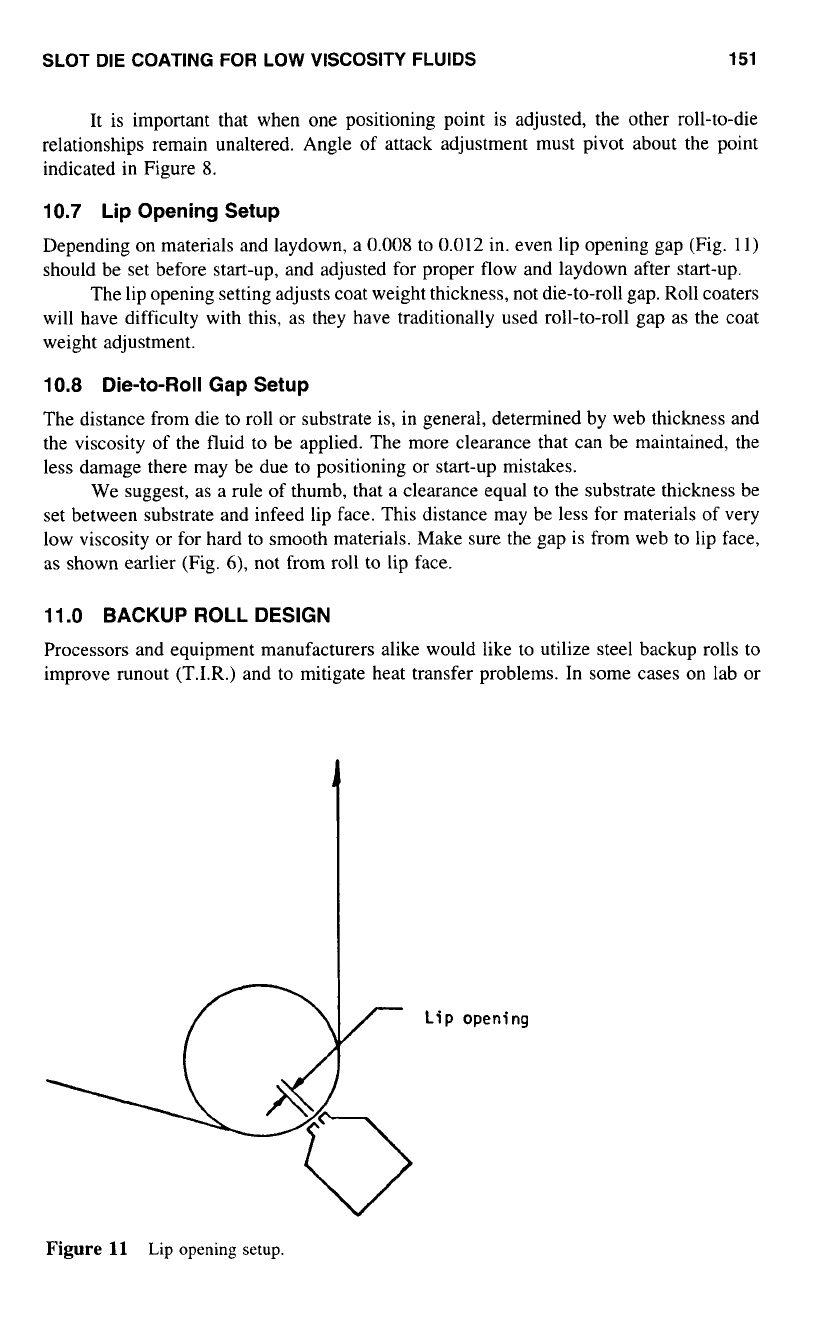
10.7
Lip Opening Setup
Depending on materials and laydown, a
0.008
to
0.012
in. even lip opening gap (Fig.
1
l)
should be set before start-up, and adjusted for proper flow and laydown after start-up.
The lip opening setting adjusts coat weight thickness, not die-to-roll gap. Roll coaters
will have difficulty with this, as they have traditionally used roll-to-roll gap
as
the coat
weight adjustment.
10.8
Die-to-Roll Gap Setup
The distance from die to roll
or
substrate is, in general, determined by web thickness and
the viscosity of the fluid to be applied. The more clearance that can be maintained, the
less damage there may be due to positioning
or
start-up mistakes.
We suggest, as
a
rule
of
thumb, that a clearance equal
to
the substrate thickness be
set between substrate and infeed lip face. This distance may be less for materials of very
low viscosity
or
for hard to smooth materials. Make sure the gap is from web to lip face,
as
shown earlier (Fig.
6),
not from roll to lip face.
11.0
BACKUP
ROLL DESIGN
Processors and equipment manufacturers alike would like
to
utilize steel backup rolls
to
improve runout (T.I.R.) and to mitigate heat transfer problems. In some cases on lab
or
Lip
opening
Figure
11
Lip opening setup.