Raabe J. Hydro power - the design, use, and function of hydromechanical, hydraulic, and electrical еquipment
Подождите немного. Документ загружается.

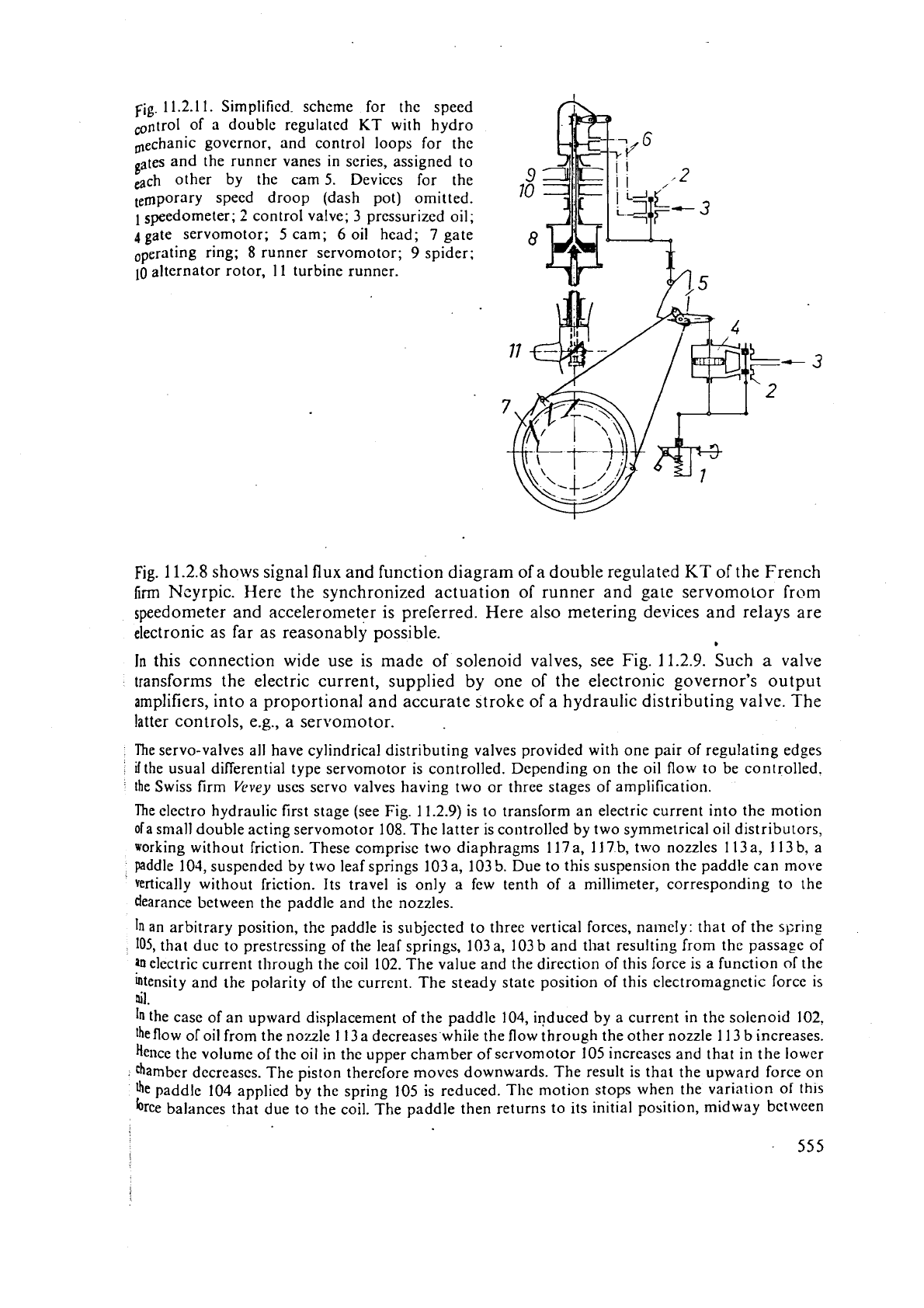
Fig. 11.2.11. Simplified. scheme for the speed
of a double regulated KT with hydro
mechanic governor, and control loops for the
gates and the runner vanes in series, assigned to
each other by the cam
5.
Devices for the
temporary speed droop (dash pot) omitted.
1
speedometer;
2
control valve;
3
pressurized oil;
4
gate servomotor;
5
cam;
6
oil head; 7 gate
operating ring;
8
runner servomotor; 9 spider;
10
alternator rotor, 11 turbine runner.
Fig.
11.2.8
shows signal flux and function diagram of
a
double regulated
KT
of the French
firm
Ncyrpic. Here the synchronized actuation of runner and gate servomotor from
speedometer and
acceleron~eter is preferred. Here also metering devices and relays are
electronic as far as reasonably possible.
B
In
this connection wide use is made of solenoid valves, see Fig.
11.2.9.
Such
a
valve
~ransforms the electric current, supplied by one of the electronic governor's output
amplifiers, into a proportional and accurate stroke of a hydraulic distributing valve. The
latter controls,
e.g., a servomotor.
The servo-valves all have cylindrical distributing valves provided with one pair of regulating edges
if
the usual differential type servomotor is controlled. Depending on the oil flow to be controlled.
the Swiss firm
Vevey
uses servo valves having two or three stages of amplification.
The electro hydraulic first stage (see Fig. 11.2.9) is to transform an electric current into the motion
ofa small double acting servomotor 108.
The latter is controlled by two symmetrical oil distributors,
working without friction. These comprise two diaphragms 117 a, 11 7 b, two nozzles
11
3 a,
I
13
b,
a
paddle 104, suspended by two leaf springs 103 a, 103
5.
Due to this suspension the paddle can move
vertically without friction. Its travel is only a few tenth of a millimeter, corresponding to the
dearance between the paddle and the nozzles.
In
an arbitrary position, the paddle is subjected to three vertical forces, namely: that of the spring
105, that due to prestressing of the leaf springs, 103a, 103b and that resulting from the passage of
electric current through the coil 102. The value and the direction of this force is a function of the
intensity and the polarity of the current. The steady state position of this electromagnetic force is
nil.
In
the case of an upward displacement of the paddle 104, induced by a current in the solenoid 102,
'he
flow of oil from the nozzle
1
13 a decreases while the flow through the other nozzle 11 3 b increases.
Hence the volume of the oil in the upper chamber of scrvornotor 105 increases and that in the lower
chamber dccreascs. The piston therefore moves downwards. The result is that the upward force on
fie
paddle 104 applied by the spring 105 is reduced. The motion stops when the variation
of
th~s
brce balances that due to the coil. The paddle then returns to its initial position, midway bct\wen
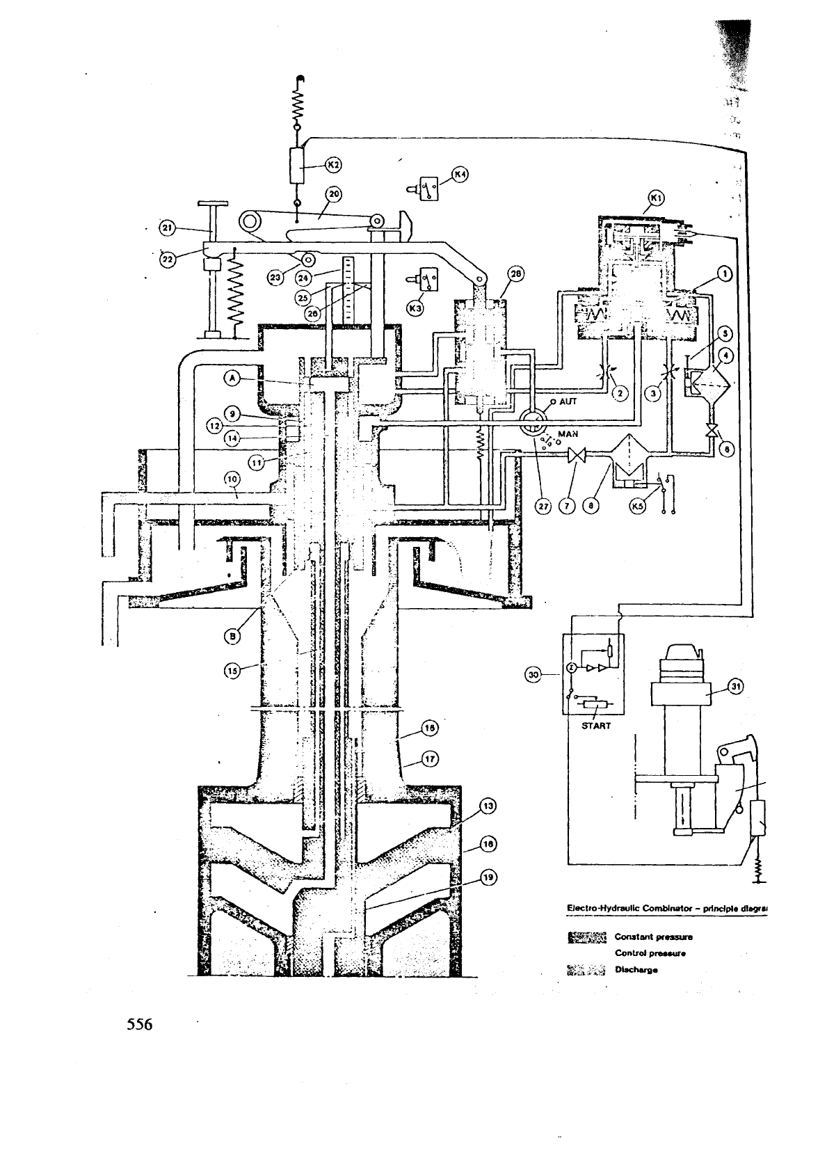
Fig. 11.2.12. Electro hydraulic runner blade adjustment by a cam according to KaMeWa
AB.
sWeden, with the control loops of gates and runner vanes in series. The input quantity to this servo
is primarily the wicket gate position. The combinator cam 29 which determines
thc relation-
ship
between blade angle and wicket gate opening is in this case connected to the pilot servomotor
*fthe actuator 31. In case large variations in head are encountered, the single cam is changed
to
a
dimensional saddle with lateral adjustment to ensure that correct setting can be achieved for
head. A third possibility is to introduce a digital processor instead of the cam or saddle.
The combinator 29 operates a transmitter K
6,
which converts the corrected mechanical guidancs
into an electric signal. The position of the regulating sleeve 9 of the combinator is also via lever 20
tIansformed in the same way by transmitter K2. Both these electrical command signals are
@mpared and amplified in the electric error detector 30, and its output signal is fed to the transducer
K
1. Pilot valve 1 actuates the regulating sleeve 9 in a direction that tends to eliminate the difference
voltage between transmitters K2 and K6. The regulating sleeve 9 is a valve for the runner
%rvomotor 13. Regulating piston 11 is rigidly connected to the servomotor piston 13. If sleeve 9 and
piston 11 do not assume identical positions, port A and
B
will be opened either
A
to discharge and
B
to pressure or vice versa depending on the sign of the error signal. Thus oil will be passed through
@ncentricducts 14 and 15 in the shaft of the runner servomotor 13 in such a way that the valve ports
will be closed again (feedback). Thus the servomotor piston 13 copies exactly the movements of
sleeve 9.
Maximum closing and opening speeds are set by means of the throttle valves
2
and 3 respectively.
Reset to a larger blade angle to start, to obtain a greater torque from the turbine, is made entirely
by
electrical means in the error detector30. Parallel to the electro-hydraulic control there is a manual
control (a general necessity for all important regulating devices in the case of emergency).
If
the 3-way
valve 27 is turned from Auto to Manual, the hand control valve 28 takes over the control of sleeve
9.
Desired runner blade angle can then be set by hand screw 21. As opposed to systems, in which
the last servo stage is located in the runner hub 18, the system described offers the advantage that
the true position of the blades can be checked. On a common
sczle 24 the position of both the
regulatiilg sleeve 9 and the runner servomotor 13, (i.e. the blade angle), are displayed. Legend
K
1
electro hydraulic transduccr,
K
2
runner blade position transmitter, K 3 limit switch fully closed,
K4
limit switch fully opened, K 5 dirt indicating switch,
K
6 gate position transmitter.
1
pilot valve
piston; 2 throttle valve, closing time; 3 throttle valve, opening time;
4
Iilter for transducer; 5 dirt
indicator;
6
shut-off valve; 7 shut-off valve;
8
filter for transducer and pilot valve; 9 combined
regulating
sleeve/difJerential piston; 10 pressure oil pipe;
I1
regulating piston;
12
pressure chamber;
13 runner servomotor piston; 14 oil duct to underside of item 13;
15 oil duct to upper side
of
item
13; 16 oil duct for static pressure to the runner hub; 17 turbine shaft; 18 Kaplan runner hub:
19
runner servomotor piston rod; 20 bell crank lever; 21 hand screw; 22 balance lever; 23 roller;
24
scale; 25 pointer for runner blade angle; 26 pointer for regulating sleeve/differential piston
position; 27 three-valve; 28 hand control valve; 29 combinator cam; 30 electronic error detector;
31
actuator. (Drawing courtesy KaMeWa, AB, Kristineham, Sweden.)
the nozzles 113a and 113 b. The final travel of the piston 108 is proportional to the exciting current
in
the coil.
The permanence of the magnetic field passing in the coil, the travel of which is very small, and the
negligible hysteresis of the spring characteristic of 105 ensure an accurate correlation between
the
movement of the distributing valve 130 alld the current in the coil 102.
Conclusion: The advantage of an electric governor consists in its high accuracy and in
lhe fact that the number of controlling and controlled parameters accompanying and
supporting the speed control and surveillance of the set is nearly unlimited. Examples
may be temperatures of bearing and alternator, blockage of by-pass outlet,
flow
of
lubricant, response of breaking elements in the gate drive, water-hammer-induced pres-
sure surge, energy exchange of a neighbouring grid, et~.
[11.39; 11.44; 11.46
to
11.481.
Moreovcl-
;ln
clcctric governor f~icilitates the col~trol of poucr st:ltions
in
remote
arm
from a far distant panel.
Fig. 11.2.10:r shows
;in
example of electronic data processing for
il
gate-regulated
from the
I
t;ilian
firm
Ilydroart. Fig.
11.2.10
b
shows special features in the control of
with single servomotors for the gates of the French firm Neyrpic.
an
Fig.
11.2.1
1
shows a simplified schemc of a double regulated
KT
with the control
looB
for gates and runner bladcs in series, in which a11 damping dcviccs such as dash pots
haye
been omitted.
Fie.
11.2.12 shows the control scheme of
a
double regulated
KT
imp&-
mcnted by the
we dish
firm KnMeWa
AD.
Fig.
11.2.13
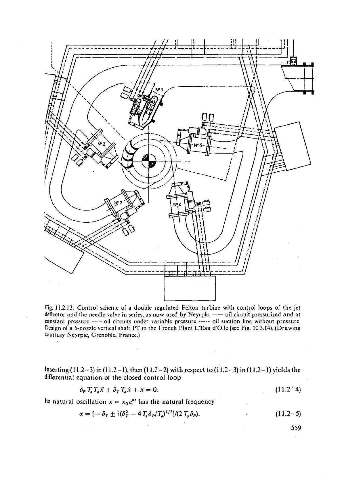
shows a control scheme of a double regulated
PT
with the control loops
of
nozzle valve and jet deflector in parallcl implemented
by
the French firm Neyr~ic.
11.2.3.
Simple
treatment
of
the
dynamic
hehaviour
of
governors
11.2.3.1.
Nomenclaturc and assumptions
I.
Symbols: d-deviation from steady state (due to speed
An
and position of servomotor
piston Am) or zero position (due to valve
A
s),
positive in the sense of speed rise
(A
n,
As)
or opening
(dm):
11,-mean speed, nl,u-stroke of servomotor piston, s,,-stroke of valve
piston equal to width of ports; related values: speed
s
=
Anji~,,,; scrvomotor
111
=
AI~/ITI,~,
valve s
=
ds/s,,,j d,.-transient proportionill band (temporary speed droop),
being
0,3 .
.
.
4(7)
for
stabilization
of disturbanccs. 'I;-regulating timc (closing
=
opening),
the servomotor piston needs to cover its stroke
s,,
at full opened valve port (s
=
1)
and
constant piston speed
In.
<-start up time of set, needed to accelerate the unloaded set
by
its rated torquc from rest to rated speed
n,
at constant acceleration. TT;-reset (isostatic)'
time, the
lilrl
2
fold time that an abruptly full-deviated dash pot piston for the elastic
feedback needs to cover its half stroke. &-rate (acceleration) time, the accelerometer
requires to cover the speed rangc
n,,,
-
n,,,
at
valve full-opened and at constant accel-
eration, (see
Fig.
11.2.3).
11.
Assumptions:
1)
No overlap and leakage of valve in its zero position.
2)
Servomotor
piston covers its stroke
s,,
in regulating time
T,
at partial opening of vilIve
s
=
3,
=
proportional band. 3) For
a
proportional governor with stiff feedback, the valve deviation
s
depends linearly on deviation of speed
x
and its integral
tit;
here at steady state
-u(s
=
0)
=
-
6,
(temporary speed droop). For a proportional integral governor with
acceleration
fecdback,
s
depends linearly on
.u
and its derivative
.t.
4)
No automatic
-
co~ltrol, torque
11s
speed graph of turbine and generator are parallel to each other.
5)
The
excess of
the turbine's torque over that of generator is proportional to the servomotor
deviation
nl.
No
water hammer. In the following
a
dot above
a
quantity indicates its rate.
11.2.3.2.
Proportional governor, servomotor with stiff feedback (speed governor)
Respecting
1)
and
3)
give the valve deviation
1) and
2)
yield the speed
m
of piston, regulating time
T,,
by
-
s
=
-
6,T,rn.
4)
and
5)
yield
the
set's equation of motion, start
up
time
T,,
by
Inserting
(1 1.2-3)
in
(1 1.2- 1),
then
(1 1.2-2)
with respect to
(11.2-3)
in
(11.2- 1)
yields the
differential equation
of
the closed control loop
dPT,T,,f
+
bTT,,x
+
x
=
0.
(1 1.2L4)
Its
natural oscillation
x
=
x,eat
has the natural frequency
a
=
[-
6,
&
i(6:
-
4~,6,/~J''~]/(2 T,b,).
(1 1.2-5)
559
After
this
thc
feedback-linked
tcrm
--
6,./(2
-T,S,)
di111ip~ oscill;~tions will1 rising
rary
JI-OO~J
A,.
;IS
set, e.g.,
by
it
Icver ratio
of
a
linkage.
ern*
.+
11.2.3.3.
Proportio~lal integral governor with ncccleration
fcetlback
(accc!crtllion governor,
PD
govcrnor)
With the rate
tirnc
T,,
respecting
3),
the valve deviation reads
s
=
T,x
+
x.
(1 1.2-6)
Expressi~lg
s
by
(11.2-2)
and then
ti1
by
(11.2-3) ~ives the
differential
equation
oftb
closed control loop, start up time
T,,
by
.-L
T,T,d,i+
T,i+x=O. (11.2-7)
Here the natural oscillation has a damping term
-
T,/2
T,
TSp that increases with the rate
,
(acceleration) time
T,.
;r
11.2.3.4.
Proportional integral governor, servomotor
with
elastic retarding
feedback
1
(PI
governor)
Let
I
be the related deviation of the spring-loaded and dash-pot-linked hinge of the valve
actuating lever.
The11
the
spring load becomes
-
I.
It
is balanccd by the hydraulic load
,
dn
the
dash
pot, which. in the case
of
laminar flow, is proportional to the speed difference
betwecn the
servomotor
(in)
and the dash pot
(0.
Accordingly with
?;.
as the reset (isostztic, isodrome) time,
Now
m
in the relation (1 1.2-
1)
has to be replaced
by
1.
Hence
Frorn
this
i
=
(S
-
i)/6,. This in (11.2-8) gives
I
=
q(m
-
s/6,
+
x/6,). Putting this and
s
from
(1
1.2-2) in
(1
1.2-9) the differential equation of the governor, input
x,
output
m,
reads
6,TT,iii
+
(6,K
+
b,T)m
+
Tx
+
x
=
0.
(1
1.2-
10)
In practice the regulating time
T,
is much smaller than
7;.
Moreover 6, is about 1110th
of
b,.
Therefore the terms with S,
7;:
are omitted in the last equation. Hence the simplified,
practice-oriented differential
equatlon of the governor
Inserting
her2
nl
from (1 1.2-3) the differential equation of the closed control loop, start
up
time
T,,
reset time
T,
reads
Here the
~atural frequency has
a
damping term
-
1i'(2STT,),
that
is
inverse to the
transient proportional band
6,.
11.2.4.
Other
time
parameters,
tuning
I.
Start up time of penstock: Because of its inertia, the
now
assumed inelastic water
column in an assumed stiff penstock'of
lellgth
L,
needs
a
period
T,,
to be speeded
up
under the head
H
to its velocity
c,,
due to the rated load. Accounting also for the speed
linked head drop by the pipe loss, assumed to
be
(c2/2, .then
T,,
follows from the energy
by (artanh
z
tanh-
')
T,,
=
L
{2/[gH(1
+
n]}
'I2
artanh {c,[(l
+
0/(2gH)]1'2}.
(1 1.2- 13)
or
the usual case ~,/(2gK)'~~
%
1, this becomes
T,,
=
cr Ll(g
HI.
11.
Opening time of distributor,
To:
Obviously this has to last longer than the start up time
d
the penstock. Hence
7;,
$
To.
111.
Reflection time, closing time: Any shut down of a turbine on a penstock causes water
hammer, propagating with velocity
a
along the penstock, length L. At the latter's upper
the wave is negatively reflected and returns to the machine after the reflection time
T,
has elapsed
I
/
~ccording to Cap. 8.3, decreasing the pipe velocity within the period
T,
by Ac, i.e. by
i
closing the distributor, generates a pressure rise at the lower pipe end
'
The closing rate of the distributor is usually decelerated in a stepwise manner towards the
.
closed position. This has to be done as described in Cap.
8.3
with respect to reflected
water hammer waves, the rotary inertia of the set, and the characteristics of the hydro
turbomachine in the regime concerned, as a function of distributor opening and speed.
1
A
fairly dimensioned timing of the closure is signified by the fact, that the maximum
1
pressure increase, set before and mentioned in Cap. 8.3 is never surpassed but used as
often as possible.
1
Usually the relative pressure rise due to water hammer is prescribed by
A
H/H
=
0,l to
;
1
for H
-
1000 m to 10 m. To keep the pipe loss under rated load below
1
%
of the head,
1
the rated pipe speed is chosen in the range
c,
=
0,l (2gH)'I2. Making the velocity change
:
Ac
in (1
1.2-
16) equal to this
c,,
then
An
example
I-i
=
500
m,
a
=
1000 m/s with the result AH/H
=
2,02 demonstrates that at
least in the relevant high head range, a closure within the reflection time would yield
unacceptably high water hammer pressure surges. Hence in high head plants, the time
T,
may be considered as the lowest limit for the closing time
T,.
It
is known that any closure extending beyond
T,
benefits from the then occurring
attenuation of pressure surge by the negative water hammer waves reflected at the upper
end
of the pipe. Strictly speaking this hdds only for the period
T,
after the time elapsed
I=
T,.
The whole may be understood as
a
hint that any estimate of the closing time does not
negate the inclusion of
a
water hammer calculation.
Generally any waterhammer destabilizes the loop of the governor in so far as it creates
a
pressure
rise
upstream of
a
closing valve and hence counteracts the intended reduction of flow. Problems of
Eovernor stability together wit11 water hammer are dealt with in the following Cap.
11.3.
Hence any closing time
T,
that is predicted, from the set's moment of inertia
O,
its full load torque
M,,,
and a desirable limit of overspeed
do,
e.g. at short circuit, by application of the equation of
motion
7;
=
/1(1>0,'(~
(1
1.2.qo
.
.
rcquires
;III
cnipiric;~l cnrrcctio~i frlctnr
y.
Thc
similarity requircs
MI,,
-
(1)'
D'.
dto
-
(0.
hssu
7
and
7.
10
ht:
const;lnt, thc ;~horc yiclds
O
-
D5ar.
This rcflects~thc known fact. that
[he
regu,w
"?%
moment of incrtia incrcascs with thc spccd
w.
IV. Slar-t up time of set: Imagine the set with
n
moment of illcrtia
@
is to be Speeded
at its rated torque
M,,,
to the rated speed
o.
Hence the start up time of the set
'9
ole
that in any formula with
@
the effect of added water mass should be accounted
but usually is not. The start
up
time
T,
of the set should exceed the start up time
of
the
penstock after
(1
1.2-
1
J),
according to
q,
$
<.
To develop the rated torque at start
up
the opening time of distributor
To
has to fall short of the start
up
time of the set according
to
To
s
T,.
The above can be reconciled with
T,,
s
To
under
I1
by
T,,
5
To
5
x.
11.2.5.
Special regulating devices
I.
Kaplnn
turbines: Here usually the control loop
of
the distributor is connected
in
parallel to the control loop of the runner (Figs. 11.2.7 and
8).
A
design with both the
control loogs in series (Fig. 11.2.12), but also different regulating times of the loops
favours a cam-off operation (Cap. 10.5). Both the loops, are connected by a cam (see
Fig. 11.2.12). Sometimes to reduce swell waves in navigable rivers a swell-reducing
cam
is used in case of sudden load rejection (Cap. 3.1).
To avoid
tile
consequences of reversed water hammer after water column separation,
KTs
are usually equipped with an aeration valve on the head cover, operated by the gate
ring
in the case of quick shut down (see also Cap. 8.2).
11.
Francis
turbines: Here sometimes with sets on long penstocks a by-pass outlet is uscd
to reduce water hammer, see Cap. 8.3. Aside the bep also ventilation is used.
111.
Pelron
turbines: Here a sudden load drop is encountered by
a
deflection of the jet by
means of a jet presser or cutter. The closed control loops of the jet deflector and needle
valve may
be connected
in
parallel, preferably, (Fig. 11.2.13) or in series (to date rarely
built). Both the loops are connected by a cam. This provides for
il
ready position of jet
deflector under steady state
per at ion
close to the outer edge
of
the jet. See Cap. 8.3 [1.50],
[11.2]. Quickly actuating the jet deflector allows dismissal of the cam (Cap. 5.3).
11.3.
Stabi!ity of control with respect to water hammer,
autoregulation of grid,
and
turbine characteristic
11.3.1.
Introduction
to
the
problem
Let us consider
a
set, that supplies a grid by itself. This set is controlled either by
a
PI
or
a
PD
govcrncr. It is equipped with a single regulated reaction turbine, i.e., a
FT
or a
KT
of the propeller type. The following characteristics of the turbine are known as
functions of
the
gate opening (for which. the servolnotor position
m
is taken) and the
rotary speed
,I:
a) Internal efficiency
q(m,
n). b) Unit flow
(I,,
(m,
n).
Q,
,
and n allow easy
inclusion of head oscillations.
The turbine is supplied from a long penstock with elastic response (water hammer), which
may
be single-staged or double-staged, the upper end of which
is
fed from
a
large vessel
1
tank or reservoir) at constant pressure. The turbine is attached to a generator that
1
an electric grid with a known auto regulating load characteristic due to machine
tools, pumps and blowers, or resistors,
[10.57].
Here the problem arises with respect to dynamic stability of the closed control loop
(consisting of the governor and the controlled system turbine, penstock, grid) how to set
the
reset time
?;:
of a
PI
governor or the rate time
T,
of a PD governor, and the start up
time
T,
of the set, when the characteristics of turbine and grid, the proportional band
6,,
the temporary speed droop
6,
are known or set, a certain damping coefficient is desired.
and
the natural period of the system's oscillation should not coincide with the reflection
t&e
of
the pipe.
11.3.2. Assurnptions
The natural frequency of
a
closed control loop, excited by disturbances from the grid, the
pipe system or a change of gate position or speed, is considered at a time elapsed that is
,
a
multiple of the pipe reflection time (11.2-13). The amplitudes of all the deviations
considered are infinitesimally small compared with their reference values. All distur-
I
bances are nondimensional, the time constants real times.
11.3.3. Dynamically equivalent types of governors
r
First a proportional integral governor with acceleration feed back (PD governor) is
considered, whose measuring element is of the tacho-accelerometric type. According to
Cap.
11.2.3.1 the figures used for the deviation of speed, An, servomotor piston, Anl, and
valve piston, As, respectively, are
in
which
m,
is the stroke of servomotor piston,
s,,,
that of the valve,
n,,
the rated speed.
According to (1 1.2-6) the valve deviation
s
is induced by a speed deviation
x
and its
acceleration
1.
Expressing the valve deviation s by the speed
m
of the servomotor piston,
according to (1
I
.2-2), the differential equation of the governor, proportional band (per-
manent speed droop)
a,,
reads
in
which
T,
is
the regulating (closing) time, and
T,
the rate (acceleration) time, according
to
Cap. 11.2.3.1.
Next the simplified
differential
equation for a proportional integral
(PI)
governor (servo-
motor with elastic retarding feedback), according to (1 1.2- 11) is considered. Rearranged
as
-
b,T~;-ln
=
?;:x
+
x,
(11.3-5)
in
which Tis the reset (isostatic) time and
6,
the transient proportional band (temporary
speed droop) (see Fig.
11.2.3). Obviously both the governors have a similar dynamic
khaviour when the product of proportional band and regulating time
6,
T,
vanishes
against the reset time
?;:.
According to a proposal of
G.
Fabritz
[11.2], the equivalence of
both the governors exists when the corresponding
coefficients in both relations are set
equal, according to
x=
T,
and
JPT,=6,T.
(11.3-6)
Note that thc rcguI:~tin~ time
T,
here is duc to
tl~e.PD
governor.
11.3.4.
Ishe
controlled
systcrn
(turbine,
grid,
pcrlstock)
b
1
1.3.4.1.
Gencral
remarks
on
the electric grid
With rcfercr~cc to Cap. 11.2.1.3, the grid-induced generator torque
MG
(rated value
M~),
vs speed
rt
(in rps) reads as follows
in which
lr
=
0
for a load due to machine tools,
u
=
-
1 for a load due to resistors (under
the assumption of constant voltage at the generator terminals)
and
u
=
2 for a load due
to blowers and impeller pumps 111.23; 11.571.
11.3.4.2.
Linkage
of
turbinc characteristic
and
grid
With
Q,
,
(si,
n)
as the unit discharge and
rl(m,
n)
as the shaft efficiency, both depending
on gate position
rtr
and speed n the torque of the turbi~~e, head
H,
diameter
D,
reads
During unsteady operation, the equation of motion requires
in
which
A
indicates deviation from steady state, and
O
the moment of inertia of the set.
Dividing
!his relation by the rated torque
M,
=
PN/(27ii~lv), rated output,
iz,
rated
speed, using
the identity (l/iz,) dnldt
-
(lln,) d(A~t)/dt
=
x
and accounting for the start
up
time of the set according to
the
relntio~~
(I
1.3
-9)
reads
Introducing the load degree
2
=
MT/MN, accounting for (1 1.3-7) and taking the incre-
ment
4
as infinitesimally small then
Em~loying the nondimensional infinitesimally small head deviation h
=
A
HIII,
H
rated
head, after (1 1.3-7) with dm
=
Am,
dn
=
An, dH
=
AH
and introducing the figures,
KQ~
=
Oziv!Qi
1) (aQi ~lan)~,
KQrn
=
(n1wlQI 1) (aQl llam)n,
(11.3-13)
Kqn
=
(~,v/)I) (all!Wrn,
Kqm
=
(n1,"Ill) (dllIam)n,
(1 1.3- 14)
the term
d
~CI,/ICI,
in
(1 1.3- 11) becomes
J~~TI~~~,
=
A[(K,rn
+
KQJ
m
f
(K,,
+
KQn
-
1)
x
+
3h/2].
(11.3-15)
The11 using the self control parameter,
-
K,
=
1
+
u
-
K,,
-
KQn,
(1 1.3-
16)
and accounting for
(1
1.3- 13, (1 1.3- 15),
and
relation (1 1.3-7), the equation
of
motion
of
the set, with respect to turbine characteristic and grid load, takes the form
