Raabe J. Hydro power - the design, use, and function of hydromechanical, hydraulic, and electrical еquipment
Подождите немного. Документ загружается.

which may entail starting and stopping 10 times a day. With a reversible set
the following additional factors affect the generator design: hydraulic machine character-
istics, dual rotation, methods of starting the units in the pumping mode.
The present insulation design provides a built-in overload capacity, which can sometimes
be used by operating the turbine at a gate opening greater than the specified one. Pumped
storage involves frequent mode changes, starts and stops, and even reversal of rotation
and in aggregate these will amount to several thousand significant load changes per
nnnum. The epoxy-resin-based insulation system is designed to withstand this rapid
cyclic duty.
11.4.1.5. Special machines for low
head
-
The rim generator of Straflo turbines (Cap. 10.2) could prove to be the economic means
of generating electric power from the tides at selected sites, including several river estua-
.
ries, in the
UK.
Ratings of up to 50
MVA
at 60 rpm have been considered. Such generator
would have a rotor diameter of 12
m.
This design combines excellent cooling by the
discharge passing the rotor bore with an easy accessibility of the alternor. Highest
possible natural fly-wheel mass ensures stable regulation.
11.4.1.6. Operating
regimes
In the past, very many hydroelectric installations were built as base load stations, but
with the changing pattern of generating capacity in an interconnected system, attention
is being given to re-assessing the role of these existing machines. In many cases it would
be more
ecor~omical to operate the sets as peak-load stations with the added security of
quickly available standby capacity.
To
achieve this, would mean increasing the installed
capacity by 25 to 50 per cent
and running at reduced load factor
cp;
see also [11.61].
Increasing the rating of the station could be achieved in a number of ways among which
uprating thc existing generators is immediately attractive. Replacing the existing bitumen
based stator windings by modern epoxy windings would permit a substantial increase in
permissible rating
both by increasing the volume of copper ir. the machine and by
providing an insulation system of much improved thermal conductivity.
11.4.1.7. Computerized design
Computer techniques for the electromagnetic and mechanical ciesign calculations are
increasingly being developed and these enable more detailed design studies to be carried
out before the final design is established
[11.60].
11.4.2.
Alternator, eIectric features
The alternator consists of
a
rotor as a carrier of
a
magnetic field with a magnetic flux
@.
This is obtained by a certain numberp, of pairs of
DC
excited poles uniformly distributed
around the circumference of
the rotor.
The rotor is driven by the hydroturbine. This has a speed
n[rpm], resulting from its head
H
and its essentially head-conditioned unit speed
n,,
(see Cap. 9.2) and a noininal
diameter
D,
(from now on instead of
D
which henceforth denotes the diameter of the
alternator rotor) of the turbine runner. Thereby the magnetic field of the poles, uniformly
distiibuted around the circumference, induces in the
z,
windings of they, pairs
of
poles
an effective internal voltage (in volts)
f
=
C
1
zP
j),.@,
(11.4-1)
whcrc
C,,
is consLil~lt
=
9,517
-
atld
9
thc e~ectivc tn;~gnctic flux in
i~lor,,,,,,,
I-~;~rr~lonic;~ll
y
varying around the circumferunce.
'rhc
grid frequency
/,
the number of pole pairsp,, and 11-~e spccd
11
or the angul
I
of set
(I,
are relatcd by
r velocity
In rarc c;tses \vith larse variations of head and thereby widely changing optimilm
speed
,I,
the speed a!ld the number of pole pairs either in the rotor or in the stator of alterllator
may
be changed at
\\ill
in two steps, especially when the ~naclline is a motor-generator
af
a pump-tarrbine uscci for turbine and pump operation, scc Cap. 11.4.7.
When
the alternator is loaded with its current
I,
then thc internal voltage
E
differs from
the effective voltage
U
at the alternator termirlals by the following voltage drops to be
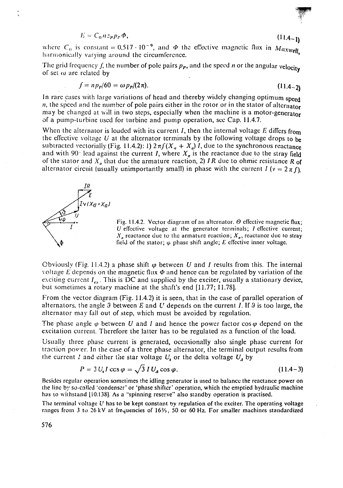
subtracted vectorialiy (Fig.
1
1.4.2): 1)
2
nf(X,
+
X,)
I, due to the synchronous reactance
and with
90-
lead against the current I, where
X,
is the reactance due to the stray field
of the stator and
X,
that due the armature reaction,
2)
I
R
due
to ohmic resistance
R
of
alternator circuit (usually unimportantly small) in phase with the current
I
(v
=
2
n
f).
Fig.
1
1.4.2.
Vector diagram cf an alternator.
O
cffcctive magnetic
flux;
U
efTcctive voltage at the generator
terminals;
1
effective current;
X,
reactance due to thc armature rcacrion;
X,,
reactance duc to stray
field of the stator;
q
phase shift angle;
E
effective inner voltage.
Qbviously
(Fi_e.
11.4.2)
a
phase shift
cp
between
U
and
I
results from this. 'The internal
{oltage
E
depencis
on
the
magnetic
flux
(D
and hence can be regulated by variation of the
elcitinz ctirr'cnt
I,,
.
This is
DC
and supplied by the exciter, usually
a
stationary device,
but sometimes
a
rotary machine at the shzft's end [11.77; 11.781.
From the vector diagram
(Fig.
11.4.2) it is seen, that
in
the case of parallel operation
of
alternators. the ansle
3
between
E
and
L'
depends on the current
I.
If
3
is too large, the
alternator
may
fall out oT step, which must be avoided by regulation.
The phase angle
cp
be:ween
U
and
I
and hence the power factor cos
cp
depend on the
excitation current. Therefore the latter has to be regulated
as
a
function of tlie load.
Us~~ally three phase current is generated, occasionally also single phase current for
traction pot1-er-.
In
the case of a three phase alternator, the terminal output results fr~m
the carrcnt
:
and eit!ler
tile
star voltage
L',
or the delta voltage
U,
by
P
=
3~,1ccs~
=
~~IU,COS~.
(1
1.4-
3)
Resides regulilr operation sometinies the idling generator is used to balance the reactance power on
the
line
by
so-cnl1c.d 'condenscr' or 'phase shiftcr' operation, which thc emptied hydraulic machine
has
to \vithstand
liO.1381.
As
a
"spinning reserve" also standby operation is practised.
The
terminal vo:tagc
ir
has
to
be
kept constant
by
regulation of tlie exciter. The operating voltage
.
ranges
fro111
3
to
26
kV
at
frequencies
of
16%,
50
or
60
Hz.
For smaller machincs standardized
voltages are recommended. Optimum magnetic and electric utilization of the machine is achieved.
when the voltage can be freely
selcctcd. According to experrence, the voltage increases with the
output
P.
This can be approximated by a logarithmic law
PIPo
=
In(UiU,),
where
P,
and
Uo
are the
output and
voltagc of a certain plant.
Excepting traction power with its grids of 16% and
25
Hz,
the frequency of AC grids is standardizcd
at 50, or 60
Hz.
Therefore regulation of an alternator to cover a certain load demand implies
constant terminal voltage under nearly constant speed according to
(1
1.3-2) and the proportional
band (permanent speed droop) of the governor (see
11.2).
11.4.3.
Design features with respect
to
critical speed
I.
General remarks: The design of alternator rotor, its shaft and bearings is influenced by
the effort, to shift the critical speed to the desired high level (usually above runaway) at
reduced cost. Therefore low head sets with low runaway speed show in general the two
bearing design with an overhung arrangement of turbine runner
and alternator rotor. In
order to reduce the distance of the rotor's centre of gravity from the guide bearing centre,
the umbrella or semi-umbrella design (Fig.
10.2.1.3)
is preferred.
The shortening of this distance also under higher head, when the large rotor mass then does not
allow this design, is one of the decisive needs for a high critical speed. Moreover such a speed requires
also a small mass of alternator rotor. As the latter is always larger than that of turbine runner, the
design has to be focussed on this small distance between rotor and its adjacent guide bearings.
The dominating mass of alternator rotor is a typical feature of hydroturbine sets especially in the
high head range. It requires corresponding machine tools. partly fabrication on site, a stress relief
oven there, or transportation facilities with sufficient loading gauges, also cranes at the shop and site
respectively, depending on the construction and the mode of rotor fabrication (in shop or on site)
as well as on the existence of a satisfactory erection bay.
11. Fly-wheel effects: The big rotor mass suits the large moment of inertia often required
for stable speed control and for limitation of overspeed after sudden load rejection. This
holds especially for smaller and high-speed units.
The fly-wheel effect of the rotor also effects the torsional vibration and thus the dimensioning of the
shaft in
some cases. The shaft diameter should then be selected so that no danger occurs in thccase
of short circuit or faulty synchronization and the critical torsion spccd range
IS
avoided when thc
torque varies.
If the synchronous machine can be dimensioned for optimum electrical and magnetic utilization,
without mechanical overstressing, the rotor has the so-called natural fly-wheel effect.
If a fly-wheel effect greater than
the natural one is required, it
is
necessary to increase the bore
diameter so far as mechanical stresses permit (so-called fly-wheel type rotor).
II'
it
is desired to retain the borc diameter corresponding to the natural fly-wheel effect, the required
m,
R2
can be achieved by an additional fly-whcel with a diametcr larger than that of the stator bore.
For reasons of accessibility in vertical sets, this fly-wheel is installed underneath the bore. It is then
no longer possible to install and
dismantlc the complete rotor
(+
fly-wheel) through the stator bore.
The physical origin of the
largc rotor mass in relation to that of the turbine runner, especially striking
at high-head machines, results on the one hand from the modest strength of the magnetic field in
iron even under saturation. On the other hand it results from the limited admissible density of
current in
the conductor, to avoid heat stresses and damage of insulation by waste heat. As a result
the force between rotor and stator is combined with a rather low pressure
(I
to
2
bar) of the
conductor bars on the radial walls of the notches. This could be overcome by cryogenics.
Against that the hydraulic reaction turbine at a
head
H
has a
differential
pressure about
g
y
H
on
the rotor vanes, yielding up to 70 bars. Moreover the propelling force on the
runner is extended over
the-whole
vane-fillcd space of the rotor, whereas in the alternator rotor it is limited to the surface
near thc gap between rotor and stator.
111.
Shaft ditlmetcr duc to critics1
speed
nnil
rotor mass:
The
shaft di:lmclcr is
usual,
Y
dctermincd
by
the nccd, to set tlie lowest critic:ll
speed
u),,
due
to flcxural vibrations
somc~vh:lt
~I!>OVC
tlie ruIl:I\il:Iy speed cora (scc also Cap.
10.5).
According
to
the similarity
Ia~vs (Cap.
9.2)
or,
=
z3;'
i
K~~(~~IIJ)'~~/D~,
(1 1-4-4)
where D, is from now
on
the runner diameter of the turbine, Ktr its rated blade speed
coefficient, and
i
its runa;Nay to rated speed ratio (a type-conditioned figure).
The critical speed
(I),,
is
mainly determined by the imaginary deflection f.of the horizon,
tally assumed shaft under the weight nt, of the alternator rotor, according to
The mass of the rotor, density
Q,,
axial length
L,
diameter D (from now on), with
LID
as a design feature, may be expressed by
n1,
-
Q,
D~(L/D).
(1 1.4-6)
With a distance betweeti the centre of the bearing and the rotor proportional to
L,
an area
moment of inertia of the shaft, diameter
cl,,,
proportional to
d:,,
the shaft deflection
becomes
f
-
9
(~/&,h)~
L2!E, (1 1.4-7)
where
E
is Young's modulus of the shaft. Inserting this in (1 1.4
-
5),
gives the lowest order
critical speed
GI,,
=
const (d,,,/~)~ (Dl
L)
(E/Q,)'/~/L.
(1 1.4-8)
Introducing the mass of the turbine runner, diameter
DT,
axial depth L,, density Q,, in
the same
way
as that of thc alternator rotor after (1 1.4-6), the ratio of the
2
rotor masses
reads
p*
=
nl,/nlT
=
(LID) (LT/DT)-
DID^)^.
(11.4-9)
Safe operation requires
wCr/ora
=
const (in general)
>=
1.
(11.4- 10)
Inserting
(1
1.4-4) and (1 1.4-
8)
in
(1
1.4- 10) and expressing
DID,
from (1 1.4-9) brings
the shaft to rotor diameter ratio
The upper limit of
d,,/D
depends on the rotor type (Cap. 11.4.7).
11.4.4.
Dimensioning the alternator rotor
I.
Diameter of the alternator rotor: Calculating the diameter
D
has to start from the
turbine-conditioned runaway speed
o,,
being
i
times the rated speed
o
(hence in terms
of angular velocity).
Thus
o,,
=
io.
Rotor dimensiolling may start from the admissible
stress
o,,
of
a
critically stressed element, usually on the outerrilost diameter
D.
Accounting
for fatigue and notch effects by a factor
k,
then in a limiting design
where
g,
is
the
mean rotor density.
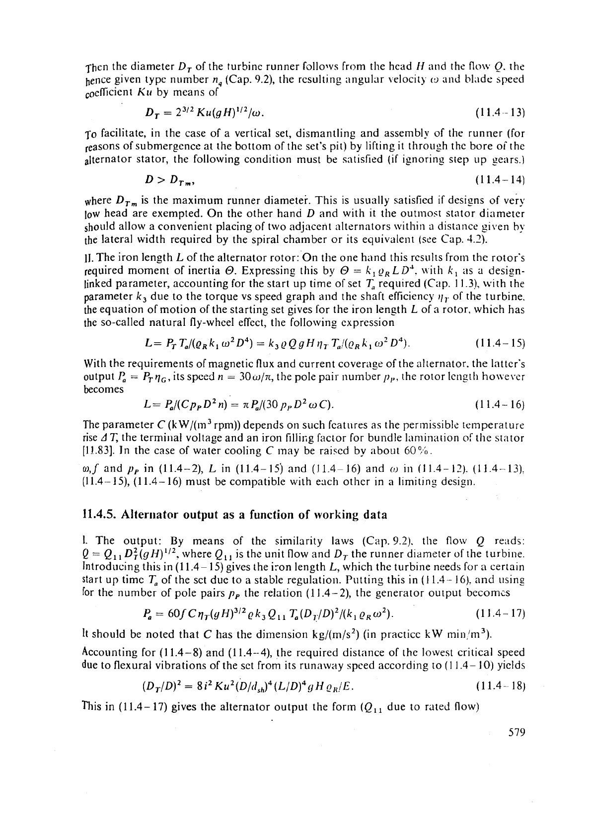
Then the diameter
D,
of the turbine runner follo~vs from the head
11
and the
flow
Q.
the
hence given type number
n,
(Cap.
9.2),
the resulting ;lngular \docit)-
(9
nrld blade speed
KLI
by means of
To
facilitate, in the case of a vertical set, dismantling and assembly of the runner (for
reasons of submergence at the bottom of the set's pit) by lifting
it
through the bore oT the
alternator stator, the following condition must be satisfied
(if
isnoring step up gears.)
where
DT, is the maximum runner diameter. This is usually satisfied
if
dcsizns of very
low
head are exempted. On the other hand
D
and with
it
the outmost stator diameter
allow a convenient placing of two adjacent alternators
\vithin a distance glven
by
the lateral width required by the spiral chamber or its equivalent (see Cap.
4.2).
11.
The iron length
L
of the alternator rotor: On the one hand this results from the rotor's
required moment of inertia
O.
Expressing this by
O
=
I;,
9,
LDJ.
\~.ith
k,
as
a
design-
linked parameter, accounting for the start up time of set
T,
required (Cap. 11.3), with the
parameter
k3 due to the torque vs speed graph and the shaft efficiency
11,-
of the turbine.
the equation of motion of the starting set gives for the iron length
L
of
a
rotor, which has
the so-called natural fly-wheel effect, the following expression
With the requirements of magnetic flux and current coverage of the alternator. the latter's
output
P,
=
PTqG, ils speed
n
=
30w/n, the pole pair numberp,,, the rotor length ho~vevsr
becomes
L=
P,/(C~~D~~)
=
nP,/(30 p,D20C).
(1
1.4- 16)
The parameter
C
(k
W/(m3 rpm)) depends on such features as the permissible temperat lire
rise
AT,
the termillal voltage and an iron fillifig factor for bundle lamination
of
the stator
(1
1.831. In the case of water cooling C may be raised by about 60
9.b.
w,l
and
y,
in (11.4-2),
L
in (11.4-15j and
(1
1.416) and
(1)
in
(I
1.3-12).
(11.4-13).
(11.4- 15), (1 1.4- 16) must be compatible with each other in
a
limiting desi2n.
11.4.5.
Alternator
output as a
function
of
working
data
I.
The output: By means of the similarity laws
(Cap.
9.2).
the flow
Q
reads:
Q
=
Q1,
D+(g~)112, where Q,, is the unit flow and D, the runner diameter of the turb~ne.
Introducing tl~is in (1 1.4-
15)
gives the iron length
L,
which the turbine nceds for
a
certain
start up time
T,
of the set due to
a
stable regulation. Putting this in
(1
1.4-
16).
and
using
for the number of pole pairs
p, the relation (1
1.4-21,
the generator output becomcs
It
should be noted that
C
has the dimension kg/(m/s2) (in practice
kW
mirl,'m3).
Accounting for
(1
1.4- 8) and
(1
1.4-4), the required distance of the lowest critical speed
due to flexural vibrations of the
set from its runaway spced according to
(1
1.4-
10)
yields
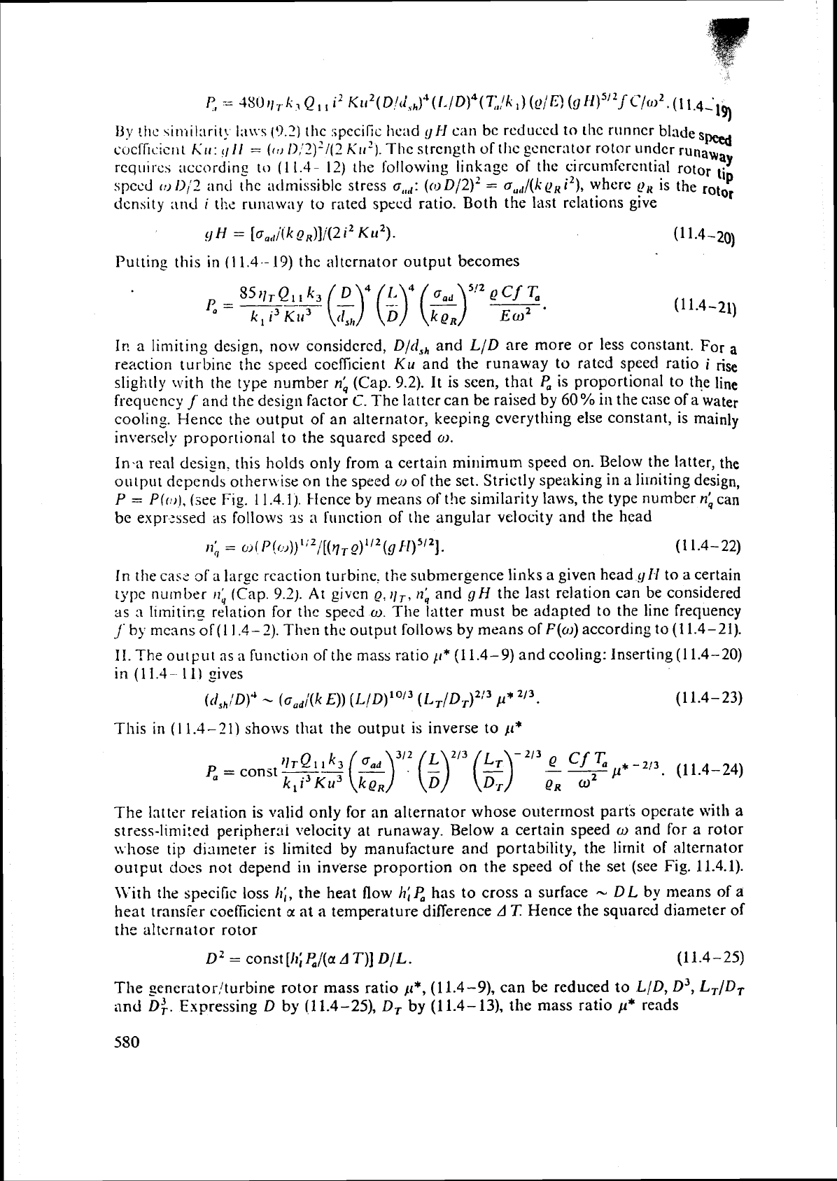
This in
(1
1.4- 17) gives the alternator output the form (Q,, due to rated flow)
U.
!tic 4iniiInrit; I;i\vs
(3.2)
the ripccific hcnd
g
H
can
bc rcduccd to lhc runner blad
sw
cuclfir.ic11
t
Ku
:
q
II
=
(rn
1),'2)'1(?
~11').
Tlic strength of thc gcncr:ltor rotor under runawal
requisc\ t~ccordlng
to
(
1
1.4-
I?)
tile
followit~g linkepe of the circunlfcrclltial rotor
tip
spccd
(u
lliZ
;tntl
the admissible stress
o,,,,:
((0
D/2)'
=
o,,,/(kp,
i2),
where
e,
is the
rotor
clenhity
and
i
the runaway to rated specd ratio. Both the last relations give
Putting this in
(1
1.4.-
19)
the alternator output becomes
Ir:
a limiting design, now considered,
Did,,
and
LID
are more or less constant. For a
reaction turbine the speed coeficient
Ku
and the runaway to rated speed ratio
i
rise
slightly with the type number
nb
(Cap.
9.2).
It is seen, that
P,
is proportional to the line
frequency
j' and
the design factor
C.
The latter can be raised by
60%
in the case of
a
water
cooling. Hence the output of an alternator, keeping cverytlling else constant, is mainly
inversely proportional to the squared speed
o.
1n.a real desip. this holds only from
a
certain mitlimum speed on. Below the latter, the
output depcnds otherli ise on the speed
o
of the set. Strictly speaking in a li~niting design,
P
=
Pfr*)),
(see
Fig.
1
1.4.1).
Hence by means
of
t!~e sin~ilarity laws, the type number
nb
can
be
expr:ssed as follows
9s
n
function of the angular velocity
and
the head
In the
cas5 of a Iarsc reaction turbine. the submergence links a given head
yH
to a certain
type
number
,I;
(Cap.
9.2).
At
given
Q,
)IT,
nb
and
gH
the last relation can be considered
as
3
11mitir.g relation for thc sped
w.
The latter must be adapted to the line frequency
j'
by
mcans of
(1
1.4-
2).
Thcn the output follows by means
of
F(o)
according to
(1
1.4-21).
I
I.
The
output
as
a
furlctio~l of the mass ratio
p*
(1
1.4-9)
and cooling: Inserting
(1
1.4-20)
ira
(1
1.4-
1
ll
gives
(tl,,,'D)'
-
(o,,/(k
E))
(IJ/D)10'3
(L=/D~)~/~
p*
2'3.
(11.4-23)
This in
(1
1.4-21)
shows that the output is inverse to
p*
The latter reiation is valid only for an alternator whose outermost parts operate with
a
stress-lin1i:ed peripherai velocity
at
rmaway. Below a certain speed
o
and for a rotor
11
hose tip diameter
is
limited by manufacture and portability, the limit of alternator
output docs not depend in inverse proportion on the speed of the set (see Fig.
11.4.1).
\Vith the specific loss
It;,
the heat flow
h;P,
has to cross a surface
-
DL
by
means
of
a
heat transfer coefficient
a
at
a temperature difference
A
'7:
Hence the squared diameter of
the alternator rotor
D'
=
const
[It;
c/(a
A
T)]
DIL.
(11.4-25)
The
generatorlturbine rotor mass ratio
p*,
(11.4-9),
can be reduced to
LID,
D3,
LT/DT
and
D:.
Expressing
D
by
(11.4-25),
D,
by
(11.4-13),
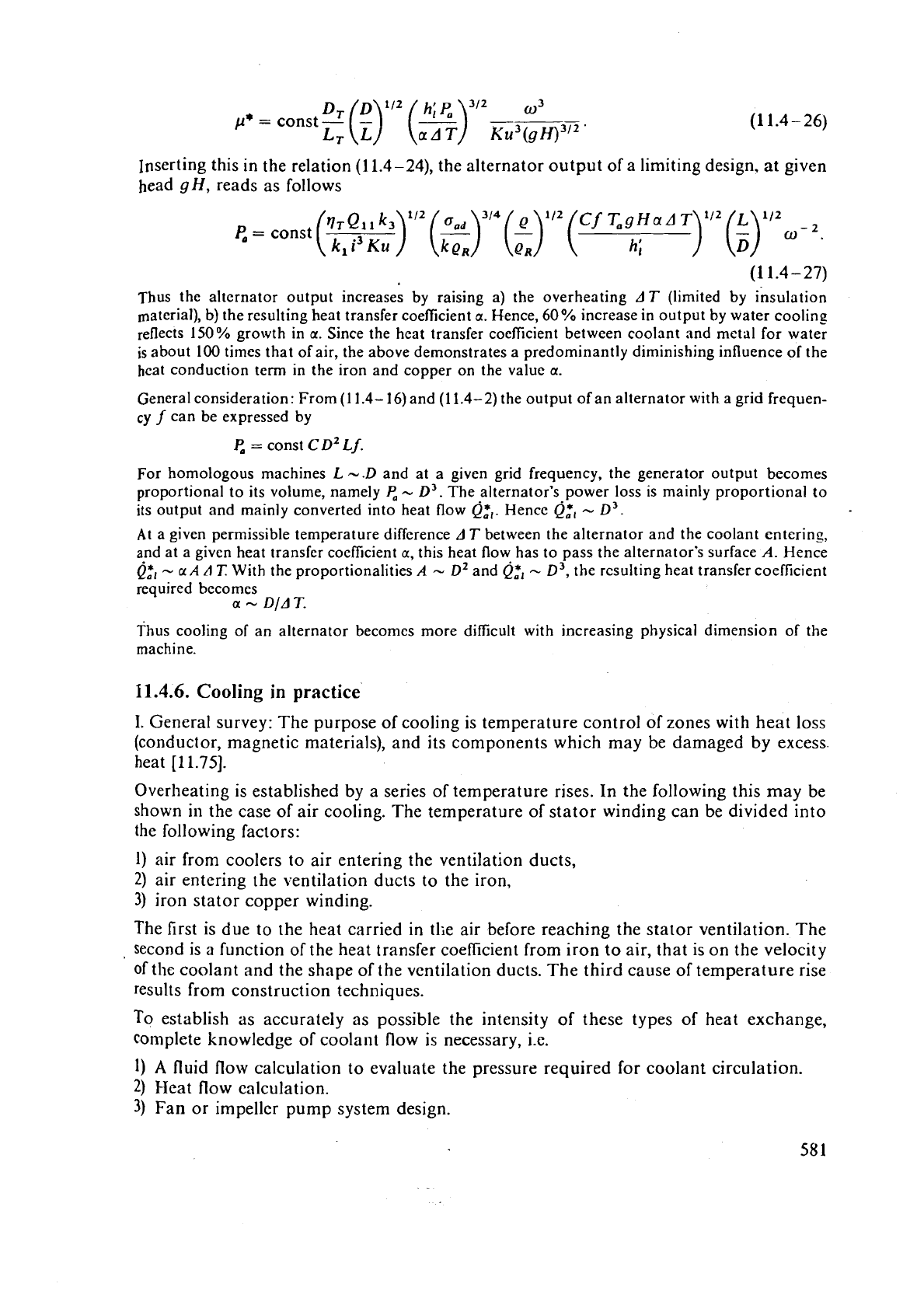
the mass ratio
p*
reads
DT
(")'I2
(4;")"'
"'
p*
=
const
-
-
L7-
L
aAT
~u~(gH)~"'
Inserting this in the relation
(1
1.4-24), the alternator output of a limiting design. at given
head
gH,
reads as follows
P,
=
const
(h~11k3)112(("314(;)"2(U~9~a~~
k,
i3
KU
'"
L
"'
k
QR
h;
)
(5)
(1
1.4
-
27)
Thus the alternator output increases by raising a) the overheating
AT
(limited by insulation
material), b) the resulting heat transfer coefficient
a.
Hence, 60% increase in output by water cooling
reflects 150% growth in
a.
Since the heat transfer coefficient between coolant and metal for water
is about 100 times that of air, the above demonstrates a predominantly diminishing influence of the
heat conduction term in the iron and copper on the value
a.
General consideration: From (1 1.4-
16)
and
(1
1.4-2) the output of an alternator with a grid frequen-
cy
f
can be expressed by
P,
=
const
CD2
Lf.
For homologous machines
L
-.D
and at
a
given grid frequency, the generator output becomes
proportional to its volume, namely
P,
-
D3.
The alternator's power loss is mainly proportional to
its output and mainly converted into heat flow
Q:,.
Hence
Q:,
-
D3.
At
a given permissible temperature difference
A
T
between the alternator and the coolant entering,
and at a given heat transfer coefficient
a,
this heat flow has to pass the alternator's surface
A.
Hence
Q:,
-
a
A
A
7:
With the proportionalities
A
--
D2
and
Q,+,
-
D3,
the resulting heat transfer coefficient
required becomes
a
-
D/A
T.
Thus cooling of an alternator beconlcs more difficult with increasing physical dimension of the
machine.
11.4.6.
Cooling
in
practice
1.
General survey: The purpose of cooling is temperature control of zones with heat loss
(conductor, magnetic materials), and its components which may be damaged by excess.
heat
[11.75].
Overheating is established by a series of temperature rises. In the following this may be
shown
in the case of air cooling. The temperature of stator winding can be divided into
the following factors:
1)
air from coolers to air entering the ventilation ducts,
2)
air entering the ventilation ducts to the iron,
3)
iron stator copper winding.
The first is due to the heat carried in
tlie air before reaching the stator ventilation. The
,
second is
a
function of the heat transfer coefficient from iron to air, that is on the velocity
of the coolant and the shape of the ventilation ducts. The third cause of temperature rise
results from construction techniques.
To establish as accurately as possible the intensity
of
these types
of
heat exchange,
complete knowledge
of
coolant flow is necessary, i.e.
1)
A
fluid flow calculation to evaluate the pressure required for coolant circulation.
2)
Heat flow calculation.
3)
Fan or impeller pump system design.
II.
Ti~c coolilnt circuit for air cooling: The circuit clesi~n depcncls or1 1-nrinus fc;l[1lrcs
of
ths
rilnc:lillc.
\Vitll
air ;is
:l
coolant nltcrilators can be divided inlo
tllc
fo!lowing groups
1)
I
ligh spoed ~e~lcriltors (small
diameter,
low pole numbers).
2)
Slow
gcilcrators (I:lr~c di:lincter, large pole numbers).
3)
Reversible
motor-gcncrntors for pump-turbines and tlon reversible rl~otor-gencrat~~~
for ternary pumped storage scts.
In air-cooled machines
a
distinction is also made between axial arid radial ventilation,
where the first is preferably employed in the group 1) and the latter in group 2). Both
methods of cooling can be used in an open or closed system.
With
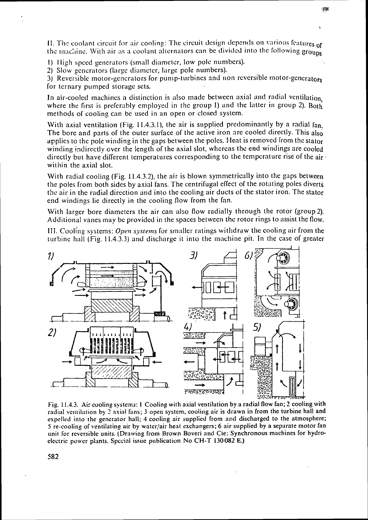
axial ventilation
(Fig,
11.4.3.11, the air is supplied predominantly by a radial
fan.
The bore and parts of the outer surface of the active iron are cooled directly. This alsd
applies to the pole winding
in
the gaps between the poles. Heat is removed from the stator
winding indirectly
over
the length of the axial slot, whereas the end windings are cooled
directly but have different temperatures corresponding to the temperature rise of the air.
within the axial slot.
With radial cooling (Fig.
11.4.3.2), the air is blown symnletrically into the gaps between
the poles from both sides
by
axial fans. 'The centrifugal effect of the rotating poles diverts
the air in the radial direction
and into the cooling air ducts of the stator iron. The stator
end windings lie directly in the cooling flow from the fan.
With larger bore diameters the air can also flow radially through the rotor (group 2).
Additional vanes may
bc providcd in the spaces between the rotor rings to assist the flow.
111.
~ooli'n~ systems:
Open
systerns
for smaller ratings withdraw the cooling air from the
turbine
hall
(Fig.
11.4.3.3)
and discharge
it
into the maclline pit. In the case of greater
Fig. 11.4.3.
Air
coolin_p s!steinj:
1
Cooling with axial ventilation by a radial flow fan;
2
cooling with
radial vtntil;ltion by
2
axial fans;
3
open system, cooli~lg air is drawn in from the turbine hall and
expelled into the
generator
hall; 4 cooling air supplied from and discharged to
the
atmosphere;
5
re-coolin_c of ventilating air by water/air heat exchangers;
6
air supplied by a separate motor fan
unit for reversible units. (Drawing from Brown
Boveri and Cie: Synchronous machines for hydro-
electric power plants.
Spccial issue publication No
CH-T
130082
E.)
power loss the cooling air is preferably drawn from the :~tmosphere via filters and ducts
and
subsequently discharged
(Fig.
11.4.3.4).
The air can be discharged through openings
ia
the warm air duct and used for he;~ting the power house if necessary.
The closed system is used when the atmosphere is polluted and for high output machines.
The air circulates in a closed circuit and is re-cooled by waterlair heat exchangers
(Fig.
11.4.3.5).
It is possible to maintain an almost constant operating temperature by
metering
the quantity of cooling water or mixing warm water with the cold water
according to the load on the machine. The heat exchangers are either flanged
to
the stator
frame or let into the foundation cooling ducts.
synchronous machines for reversible operation (group
3)
and pole changing two-speed
machines
are ventilated separately. The cooling air is supplied by motor driven fan units
(Fig.
11.4.3.6).
~urther efforts to increase the specific output and improve the utilization of the machines
have led to the application of liquid cooling. The economic advantage of liquid cooling
is
dependent on the evaluation
of
losses. Its application is particularly justified for high
outputs and high speeds. Moderate values of fly-wheel effect (bulb generators) permit
full
utilization of the advantages of liquid cooling.
IV.
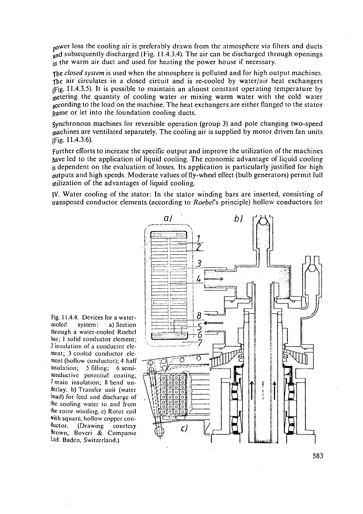
Water cooling of the stator: In the stator winding bars are inserted, consisting of
transposed conductor elements (according to Roebel's principle)
hollo\v conductors ior
Fig.
1
1.4.4.
Devices for
a
water-
cooled system:
a)Section
through a water-cooled Roebcl
bar;
1
solid conductor
elcment;
2
insiilation of
a
conductor ele-
ment;
3
cooled conductor cle-
ment
(hollow conductor);
4
half
insulation;
5
filling;
6
semi-
conductive
potential
coating;
7
nlain
insulation;
8
bcnd un-
derlay.
b)
Transfur
unit
(watcr
head)
for feed and discharge of
thc
cooling
water
to and from
the rotor winding. c) Rotor coil
With
square, hollow copper con-
ductor. (Drawing courtesy
Brown, Bovcri
&
Cornpanic
Ltd.
Badcn, Switzerland.)
thc cooling watcl- (Fig. 11.4.Ja). The cooling watr:r is supplied to
the
st:\tor wind'
'
and rernovcd by a closed circuit system of pipus or
a
ring main spjlcrn arranged
the wlncli~igb
in
thc stator frame. The insulation bclwccn thc stator windings
cooling systcm
is
provided by Tcfloll hoses.
%
!T
The iron losses of the stator laminatiol~ are likewise relnovcd by coolinp water.
12
V.
Water cooling of the rotor: The cooling water is kd to the rotor winding and
remo,,o;i
via
;I
transfer unit on the end of the shaft (Fig. 11.4.4 b). concentric stainless steel
in the shaft bore carry the treated cooling water via flexiblc conncctioas to the manifoldr
nloui1ted on the rotor. The water then flows via insulating boses into the hollow conduo
tors of the pole windings (Fig. 11.4.4~). The iiquid cooling sysl-m consists of two circui(r
The first circuit supplies treated, i.e., de-ionized, oxygen-free water Lo the stator and
rot&
winding system. The other circuit supplies untreated fresh water to the stator end
plalo
and the back of the stator iron.
a-
The conductivity of the treated water, the relative llu~nidity inside the stator frame
a
the circulation of the liquid are monitored continuously.
Fig. 11.4.5 a shows the sectional drawing of the
fi~lly
water-cooled alternator at
~~~~t~b,
Ncrway, built by
BBC,
to prove the reliability of this design. Fig. 11.4.5b shows
a
perspective sectional drawing of the alternator ltaipfi, Rio Parank Brazil, at present one
.
of the largest water-cooled alternators in the world, built by
BBC
and Siemens.
But
here,
only the stator is water cooled.
1
1
A.7.
Rotor construction
The output, runaway speed, and the required fly-wheel effect largely determine
the
construction of rotors. Assembly and transport limitations are often additional criteria
which affect rotor constructio11. The shaft dirnensions are determined by the critical
flesural and torsional speed, which must be in adequate distance from the interfering
excitation frequencies. Fig.
11.4.6 shows different bearing arrangements.
I.
Rotor body: Rotors for small number of poles and sniall bore
diameters
are constructed
as solid forgings (Fig.
11.4.7.1). The shaft and central body form one unit.
In
rotors with
a larger number of poles and larger bore
dianleters the heavy central section is replaced
by
a
cast or forged hollow body with shaft ends flanged on to both sides (Fig.
11.4.7.2).
Rotors for large capacities and medium number of polcs are preferably constructed
as
disk rotors (Fig. 11.4.7.3). The central body is formed of several rolled steel plates centred
in relation to each other by spigots or mating rings and compressed by prestressed
clalnping bolts. The shaft ends are also flanged to the rotor body by means of clamping
bolts.
The central section can be replaced by
a
cast steel spider with several shrunk-on forged
steel rings (Fig.
11.4.7.4). Rotors for larger diameters and medium to low speeds are
constructed
with laminated rims. They have a continuous shaft with a shrunk-on spider,
or shaft ends flanged to the latter (Fig.
11.3.7.5). The spider consists of a cast, forged or
welded hub with attached arms, which can
be
onscrewed or are welded to the hub
depending on transport limitations. The rim consists of segments of steel laminations
each several
millinleters thick. l'he punched segments overlap each other and are corn-
pressed by clamping bolts
to
form a ring resistant to bending. With the usual overlapping
of one pole pitch. at the joint between the individual segments, the critical cross-section
for the strength analysis deviates less from the full ring cross-section, the greater
is
the
number
of
pole pitches in
a
segment.
