Raabe J. Hydro power - the design, use, and function of hydromechanical, hydraulic, and electrical еquipment
Подождите немного. Документ загружается.

From 9.2
it
is known that the.torque vs speed characteristic of a turbine decreases always
,,g
the speed.
In
contrast, the slope of the generator torque characteristic depends on the grid load,
whereas the turbine characteristic can
be
changed (by means of the gate position). The
perator characteristic results from the accidental grid load. This causes the main
disturbance to the control loop considered.
~ssuming the intersection point of both the characteristics to be stable and neglectin?
inertia effects, the momentary speed of a set would result from the accidental position of
the intersection point of both characteristics. Now the essential task of the speed governor
of
a leading plant is to have a settled speed .at the intersection point that is assigned to
the load according to the proportional band (permanent speed droop) of the set,
i.e.,
adapting the gate position to the randomly varying grid load.
Fig. 11.2.3 shows typical curves of grid-load-induced generator torque vs speed. Curve a)
is due to machine tools, curve
b)
is due to pumps and blowers, curve c) is due
to
resistor
load (bulbs, electrolytic cells etc.). This figure reveals also the so-called automatic regula-
tion or self control of the grid by a change of load,
M,
to
M,
or
M,,
that results ultimately
in a new stable operation point
C
or
B.
This is characterized by a slope
of
the load torque
vs
speed that drops steeper than that of the turbine torque vs speed [11.23].
Contrary to this automatic regulation of a load due to machine tools or pumps and
blowers, a load due to resistors usually has no self control (automatic control). At any rate
the set requires the assistance of a speed governor for not obtaining indefinitely increasing
or decreasing speed in case of disturbances.
11.2.1.4.
The tasks
of
speed
control
I.
Frequency control: This holds especially when the alternator supplies a grid by itself
and has a set proportional band
6,
=
(n,,,
-
nmi,,)/n, (permanent speed droop). In this
n,,,
n,,, n, are the maximum, minimum and mean speed, or grid frequency in thz
working scope of the set. By the proportionzl band
a
speed is assigned to a certain load
so as to have full load at minimum speed
n,,, and zero load at maximum speed n,,.
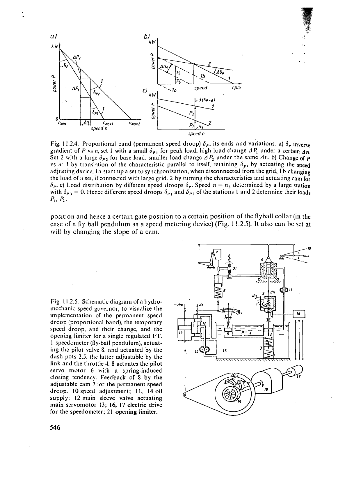
According to Fig. 11.2.4a, in consequence of a certain proportional band
6,
of the
individual sets, a certain frequency change An effects different changes
A
P,,
A
P,
to the
output of these sets 1 and
2.
Together with the speed adjustment (111) a non-vanishing
proportional band enables also synchronization of an isolated set.
By
virtue of the then
existing slope of the set's load vs
speed characteristic it is possible to effect a translation
of
the
latter by actuating the speed adjustment device such as to shift the point of zero
load from zero
speed with the set at rest to synchronous speed needed for synchroniza-
tion,
(1 1.21, Fig. 1 1.2.4 b.
In a large AC grid the frequency varies only within a rather small band of up to
1
or
2
%.
For base load plants
6,
is rather large, namely 0,04.. .0,05. This guarantees a rather
constant output when the frequency varies within a certain band.
Contrary to this in a peak load plant
6,
=
0,01
.
.
.0,02. This facilitates a rather sensibile
variation of output in the case of a modest frequency change. In other words this low
6,
enables the control of frequency especially by a powerful peak load plant 3. The frequency
load coordination by the proportional band is also important for a certain load distribu-
tion in the plants of a certain grid (Fig.
11.2.4~).
A
certain
5,
may be effected mechanically or electromechanically. The first
by
a cam
which, in the steady state position of the sleeve valve, assigns a certain servomotor
speed
n
Fig.
11.2.4.
Proportional band (permanent speed droop)
S,,
its ends and variations: a)
6,
inverse
gradient of
P
vs
n,
set
1
with a small
6,,
for peak load, high load challge
LIP,
under a certain
An.
Set
2
with a large
ci,,
for base load, smaller load changc
AP,
undcr the same
An.
b) Change of
p
vs
n:
I
by trnnsl:ition of the characteristic parallel to itself, retaining
d,,
by actuating the speed
adjusting device, la start up a set to synchronization, when disconnected from the grid,
1
b changing
the load of
ii
set. ifconnected with largc
grid.
2 by turning the characteristics and actuating cam
for
6,.
C)
Load distribution by different speed droops
6,.
Speed
n
=
n,
dctcrmined by a large station
with
(5,,
=
0.
Hencc diflerent speed droops
S,,
and
S,,
of the stations
I
and
2
determine their loads
47
1;.
position and
heme
a
certain gate position
to
a
certain position of the flyball collar (in
the
case
of
a
fly
ball
pendulum as a speed metering device)
(Fig.
11.2.5).
It also can be set at
will by changing the slope
of
a
cam.
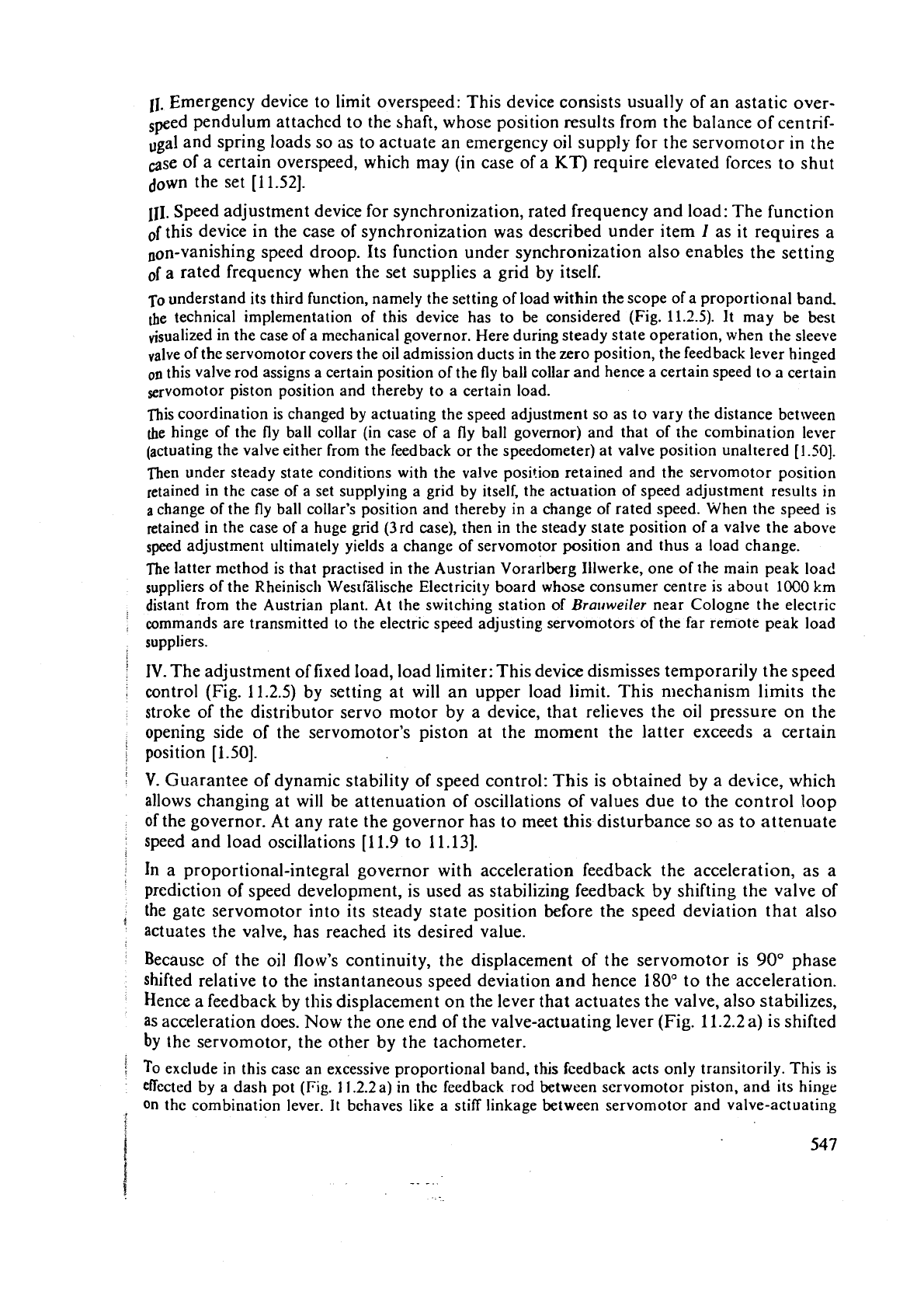
Fig. 1 1.2.5. Schematic diagram of a hydro-
mcchanic speed governor, to visualize the
irnplemcntation of the permanent specd
droop (proportional band), the temporary
speed droop, and their change, and the
opening
li~nittr for a single regulated
IT.
1
specdometcr (fly-ball pendulum), actuat-
ins
the
pilot valve
8,
itnd actuated
by
the
d:~sh pots
2,j.
the latter adjustable by the
link and the
tl~rottle
4.
S
actuates the pilot
servo motor
6
\\.it11
a spring-induced
closing tendency. Feedback of
8
by
the
adjustable cam
7
for the permanent speed
droop.
10
speed adjustment; 11,
14
oil
supply;
12
main sleeve valve actuati:lg
main servomotor 13;
16,
17
electric drive
for the speedometer;
21
opening limiter.
11.
Emergency device to limit overspeed: This device consists usually of an astatic over-
speed pendulum attached to the shaft, whose position results from the balance of centrif-
ugal
and spring loads so as to actuate an emergency oil supply for the servomotor in the
case of a certain overspeed, which may (in case of a
KT)
require elevated forces to shut
down the set [11.52].
111.
Speed adjustment device for synchronization, rated frequency and load: The function
this device in the case of synchronization was described under item
I
as it requires a
oon-vanishing speed droop. Its function under synchronization also enables the setting
of
a rated frequency when the set supplies a grid by itself.
TO
understand its third function, namely the setting of load within the scope of a proportional band.
the
technical implementation of this device has to be considered (Fig.
11.2.5).
It
may be best
visualized in the case of a mechanical governor. Here during steady state operation, when the sleeve
"alve of the servomotor covers the oil admission ducts in the zero position, the feedback lever hinsed
on
this valve rod assigns a certain position of the fly ball collar and hence a certain speed
to
a
certain
servomotor piston position and thereby to a certain load.
This coordination is changed by actuating the speed adjustment so as to vary the distance between
the
hinge of the
fly
ball collar (in case of a fly ball governor) and that of the combination lever
(actuating the valve either from the feedback or the speedometer) at valve position unaltered
[1.50].
Then under steady state conditions with the valve position retained and the servomotor position
retained in the case of a set supplying a grid by itself, the actuation of speed adjustment results in
a
change of the fly ball collar's position and thereby in a change of rated speed. When the speed
is
retained in the case of a huge grid (3rd case), then in the steady state position of a valve the above
speed adjustment ultimately yields a change of servomotor position and thus a load change.
The latter method is that practised in the Austrian Vorarlberg
Illwerke, one of the main peak loac!
suppliers of the Rheinisch Westfilische Electricity board who= consumer centre is
about
1OOO
km
distant from the Austrian plant. At the switching station of
Bralrweiler
near Cologne the electric
commands are transmitted to the electric speed adjusting servomotors of the far remote peak load
suppliers.
IV. The adjustment
of
fixed load, load limiter: This device dismisses temporarily the speed
control (Fig. 11.2.5) by setting at will an upper load limit. This
n~echanism limits the
stroke of the distributor servo motor by a device, that relieves the oil pressure on the
opening side of the servomotor's piston at the moment the latter exceeds
a
certain
position
[1.50].
V.
Guarantee of dynamic stability of speed control: This is obtained by a dekice, which
allows changing at will be attenuation of oscillations
of
values due to the control loop
of the governor. At any rate the governor has to meet this disturbance so as to attenuate
speed and load oscillations
111.9 to 11.131.
In
a proportional-integral governor with acceleration feedback the acceleration, as a
prediction of speed development, is used as stabilizing feedback by shifting the valve of
the gate servomotor into its steady state position before the speed deviation that also
actuates the valve, has reached its desired value.
Because of the oil
flow's continuity, the displacement of the servomotor is 90" phase
shifted relative to the instantaneous speed deviation and hence 180" to the acceleration.
Hence a feedback by this displacement on the lever that actuates the valve, also stabilizes,
as acceleration does. Now the one end of the valve-actuating lever (Fig. 11.2.2 a) is shifted
by the servomotor, the other by the tachometer.
To
exclude in this case an excessive proportional band, this feedback acts only transitorily. This is
effected by a dash pot
(Fig.
11.2.2a) in the feedback rod between servomotor piston, and its hinge
on
the combination lever. It behaves like a stiff linkage between servomotor and valve-actuating
Icvcr.
whcn
tlarnprn):
IS
ncctlcd,
when
;I
spcccl cir\tu~ b.rncc
C.III\C\
.I
r1lplrl motron ~r!cll
as
In
of sudden Io.lcl change.
-.
In the c;rsc
of
a
slow motiou, thc dash pot acts
;IS
an cl;~stic n1cnli)cr. l'liis is r~~acic pc)s5il,l
now rcluv;inr Ic;~k
agc,
sqilcczctl through tl~c dash pot's by-pass,
by
tllc spr~rls
Ic~lcl
on
the
diIsh
piston. This !old always rcturlls
lhc
hinge of tht: scrvornotor
on
tl~c cc~rl\\>irl;~tiorl lcvcr
1,)
th
WIi
C
Saw
position. This cl;l$tic fccdb;rck is also known
;IS
isostatic rcgulation.
Hencc in stabilimd steady state, when thc
V~IIVC
is
;IIS.O
at the zero position. the load does
G,
influence thc spccd in the sc~lsc of
a
proportion;ll band. Such
a
corrcla~iorl bc:\?:ccn
P
;111~1
exis(;
only during rcgulation and is ;~ttributcd to a transient propc>rtioni~! bani1
(i,.
(t~mpcjr;~~~
droop).
.To
obtain stable regul:~tion,
5,
has to bc 0.3 to 3 ir:~lites i:lrea-
t11:111
0.5
:WC
dht;lincd
on,y
electrically), that means
10
to 100 times largcr th311 tllc 11su111 propor1ion:ll
ba~~rl
(pcrmuncnt
speed
droop)
is.
For
sllort lasting. very strong load fluctuations, somctirncs thc fccclhaok is elirninatcd
at
will
by
temporarily opening the by-pass of the dash pot.
11.2.2.
Design
of
speed
and
acceleratio~~
metering
mernl~ers
11.2.2.1.
Mechanical
and
hydronlechanicsl mernbers
In the first case mentioned
a
!ly
ball pendulun~, driven by an electric
motel-,
is
r~sed, which
is
fed by
a
special pendulum alternator on
thc
shaft of the sct or
by
the
nlaitl stator
current. Instead of a fly ball,
a
pump of the ilnpeller or positive displacement type may
also be
used
as
a
tachometer.
It produces
a
specd-depeudt.11
oil
llow,
whose impact
pressure on
a
baffle plate actuates a pilot valve of thc servotnotor (Fig.
11.2.2
b).
Fig.
11.2.2~ shows
a
rather compact design oi
a
cornbincd tachomctcr
and
accclcromctsr. It func-
4em
as
follows: The radial rotating tube
is
fed by oil whosc pressurc ;ictt:atcs tht: servon!otor's valve
by
a spring-loaded piston. This pressure results Fro111 two influcnccs.
rl
specd-~o~icjitiorld compo-
nent comes from the distance the spring-suspended
fly
mass (which acts as
n
baffle plntc) is from the
radial
outlet of the rotating tube.
Tile
accelera:ion-conditioned
influence of oil pressure results frc?rn rhc
peripheral
distilnce, the
tangcntial orifice in the radial tubc
is
from
a
radial bafll~ on the incrt Jly-wheel ring. which
is
spriilg-suspended in the tangential direction.
1
1.2.2.2.
Electronic governor
The application of electronics is limited to the speed metcrin_e
or
the acceleration meter-
ing devices. The measurement of speed deviation from a
rated
value,
may
be effected by
means of
an
electronic valve or semiconductor devices like transistor. In the case of the
electronic valve, two oppositely oriented anodic
currents are controlled by the grid of this
valve. The resulting current actuates a pilot valve by
a
solenoid
[11.5].
One of thc currents is from
a
shunt of the main alternator and
is
proportional
to
the
set's
momentary speed. The other is proportional to
a
reference frzquency of an oscillatory
circuit, adjustable at will,
see
Fig. 11.2.6. Now this is effected by semiconductor devices.
At
present, data processing from pilot plants by microprocessors is corning. The concept
of
an
electronic governor head
is
based on the follo~iring principles [11.47; 11-48].
a)
The use of proven governor design philosophies has already given excellent results in
electronic governors of certain manufacturers,
e.g.
PD
speed
ar?d
speed rate governing
.
and
PI
power output governing with temporary feedback.
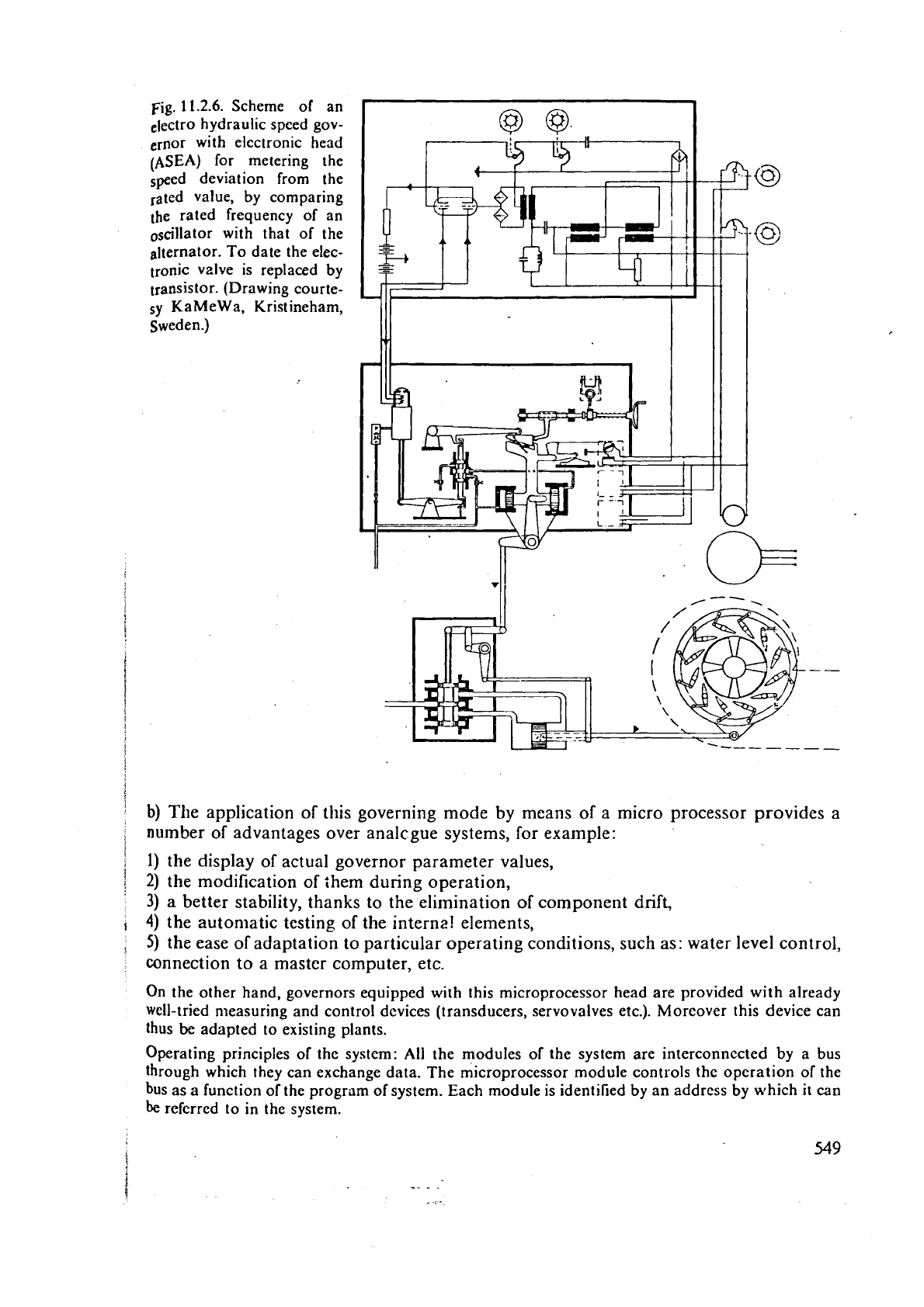
Fig.
1
1.2.6.
Scheme of an
electro hydraulic speed gov-
ernor with electronic head
(ASEA) for metering the
Speed deviation from the
rated value, by comparing
the rated frequency of an
oscillator with that of the
alternator. To date the elec-
tronic
valve is replaced by
transistor. (Drawing courte-
sy
KaMeWa, Kristineham,
Sweden.)
i
'
b)
The application of this governing mode by means of
a
micro processor provides a
number of advantages over analcgue systems, for example:
i
1)
the display of actual governor parameter values,
/
2)
the modification of them during operation,
3)
a better stability, thanks to the elimination of component drift,
4)
the autoniatic testing of the internz! elements,
3
5)
the ease of adaptation to particular operating conditions, such as: water level control,
connection to a master computer, etc.
On the other hand, governors equipped with this microprocessor head are provided with already
Well-tried
n~easuring and control dcvices (transducers, servovalves etc.). Moreover this device can
thus be adapted to existing plants.
Operating principles of
the system: All the modules of the system are interconnccted by a bus
through which they can exchange data. The microprocessor module controls the operation of the
bus as a function of the program of system. Each module is identified by an address by which
it
can
be
referred to in the system.
Dy
rncans
of
a
sequence
\vliicli is rcpcittcd very r;~pitlly. ~hc micro!)roccssor ~ucccssivcl~ qllcstio
ns
the v:lrious illput scctions such
:IS
scrvov;llvc i~mpl~licrs. indicators.or rclays. Tliis scqucllce
also
includcb 11ic [citing of irnl)ortrrnt clcmcnts and alTorcls the possibility
of
modifying pnr:lmeters
without Jisturbi~tg tlic opcrittion of the control loop.
I\
small tcr~iiinal nllo\~s
the
a<ljt~stn~~~~
parameters.
The
values displayed are thc real valucs of paramctcrs witit an accurrtcy of
T
I
%
ofthc
last digit.
The block diagram in Fig.
11.2.7
shows
Vevey
electronic and clectrohydraulic governor.
It refers
to
all
elcme~its
of
the
governing
system, the turbine being under no load condi,
tions and unsynchronized. The number in thc first colun~n indicates the line on which
an
elerndnt
is
located. Thc sccond column
specifies
the
energy sources necessary for
each
unit
of the governing system. The middle column gives the appropriate diagram. The
4th
column indicates the external controls on the governor and the servo-valves. The last
column lists the elements,
[l
1.481.
The followi~~g text will
be
limited
to
elements
of
general interest and
those
which are
suited to the Kaplan turbine considered.
Dead band device: This permits the introduction of an insensitivity into the
spced governing loop,
which is adjustable. Experience has shown that certain operators of machines block their governors
by the
gatc opening limitcr. If they have a
conveniently
sensitive governor, they thus avoid their set
continually rtttcmpting to correct the frequency variations, although the effect of such corrections
very often has no influence. Thesc incessant movements can be prejudicial to the mechanical
perforn~ance and life
cf
the governing elements.
But with this method of working at the gate opening
limihr,
if
therc is any incident in the grid, e.g.,
tripping of an interconr.ection, the outputs of all the units blocked at thc gatc opening. limiter and
supplying
the part of grid. whose frequency is decrcitsing, remain constant. F~!r:hermorc, the units
supplying the other part of the network, whose frequency is increasing. only begin to close after a
certzin delay. The result is that the disturbance in thc network may spread. The dead band has been
desig~cd precisely to prevent such incidents. When in operation, it only pcrtnits thc speed governing
sigtials to pass
if
its level reaches a previously chosen threshold.
Numerical
speed transducer: Its moving part is a magnet on the shaft. The stationary parts are a
pair of detectors. the
magnets pass in front of them. Let us assume that the magnet passes succes-
sively in front of
the detectors. The time elapsed between these two impulses received is compared
with a reference time by
means of an accurate quartz clock.
Electronic governor settings: The various settings all include, as a basic element, an angular position
electrical transducer. On the one hand it consists of magnets. that are
ilniformly distributed in the
peripheral direction on the rotary part, on the other hand it consists ofstationary detectors, arranged
around the rotary part.
-
Gate position transducer: This is of the same type used for the settings.
Temporary feedback for the runner blades and wicket gates: The clcctronic governor is fitted with
two
indcpcndcnt temporary feedbacks, acting separately on the gate and on the runner blade
positions, in the following manner: the
gate position transducer and the runner blade position
transducer
(linc
33)
in Fig. 11.2.7 enable a feedback signal of the reaction speed of the servomotor
in question to its controlling servo-valve
tc be injected separately through the corresponding
summators (line
23).
Each device has two step
selectors;
the first enables the temporary speed droop
3,
to be fixed and the second the time constant of the damping device. This is done independently
for the gates and the runner
bladcs.
Interaction bctween the wicket gatcs and the runner blades: Thc
interaction
device (line 32) which
carries out
the interaction law between the runner blade and the gate openings, which depends on
the head, receives information of the gate opening and of the operating head. From these data, it
supplies
a
signal corresponding to the requircd runner blade opening. This signal is comparcd in the
summator (line
39)
with the signal from the runner blade position transducer (line 33) giving a signal
which represents the interaction deviation.
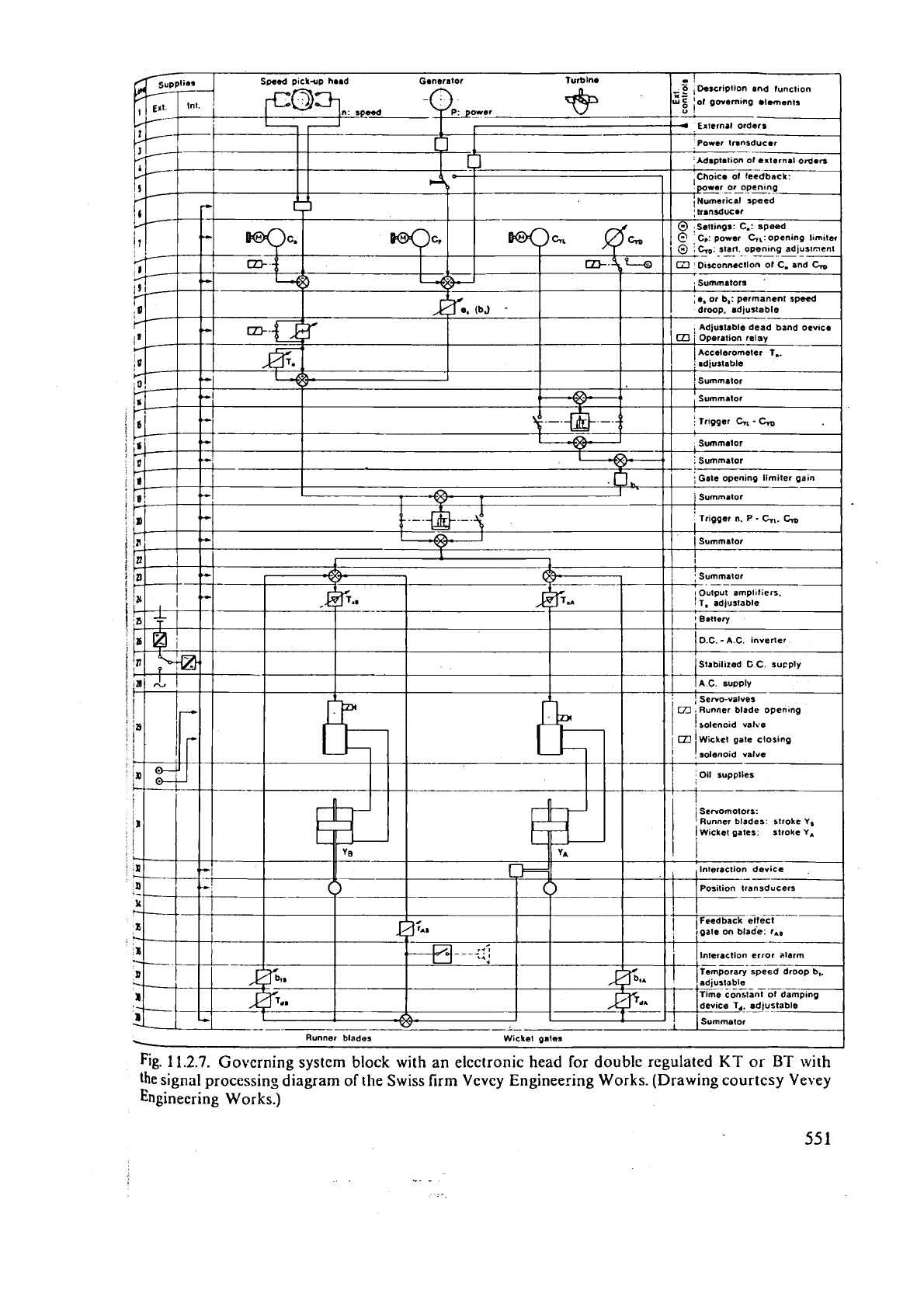
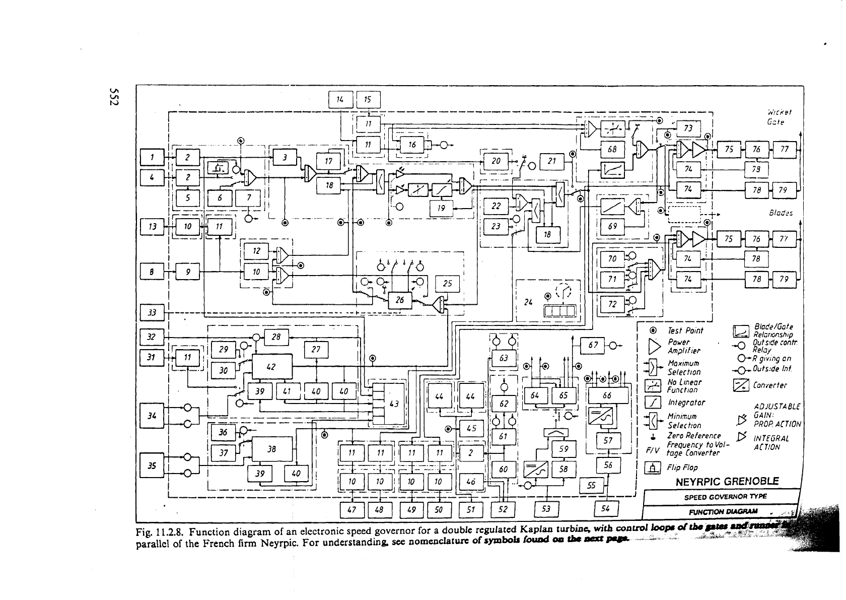
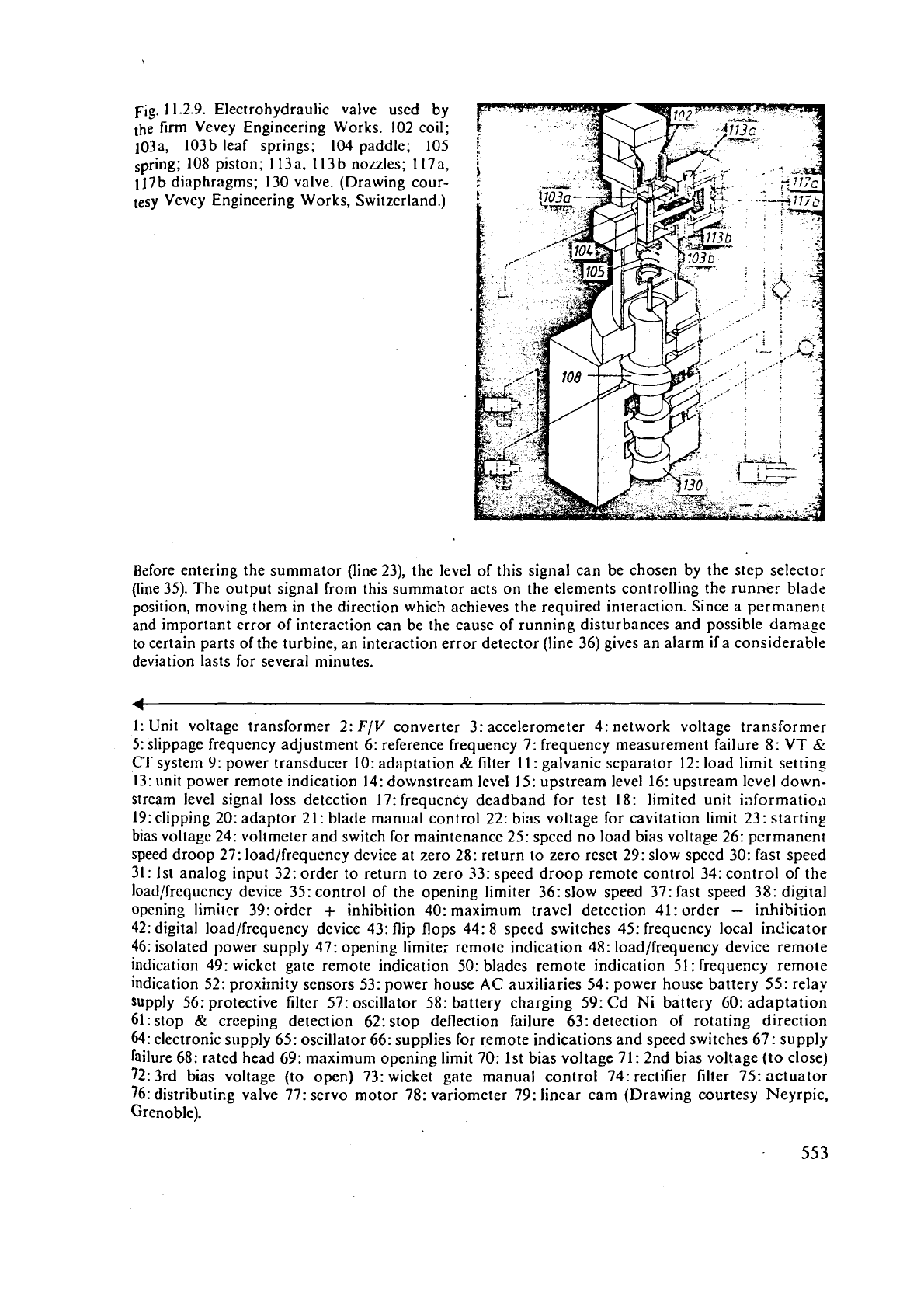
Fig.
11.2.9.
Electrohydraulic valve used by
the
firm
Vevey Engineering Works.
102
coil;
103a, 103b leaf springs; 104 paddle;
105
spring;
108
piston;
1
13a,
1
13
b
nozzles;
1
17a,
117
b
diaphragms;
130
valve. (Drawing cour-
tesy Vevey Engineering Works, Switzerland.)
Before entering the
summator (line
23),
the level of this signal can be chosen by the step selector
(li~e
35).
The output signal from this summator acts on the elements controlling the runner blade
position, moving them in the direction which achieves the required interaction. Since a permanent
and important error of interaction can be the cause of running disturbances and possible
damase
to
certain parts of the turbine, an interaction error detector (line
36)
gives an alarm if a considerable
deviation lasts for several minutes.
1:
Unit voltage transformer
2:
F/V
converter
3:
accelerometer
4:
network voltage transrormer
5:
slippage frequency adjustment
6:
reference frequency
7:
frequency measurement failure
8:
VT
6:
CT
system
9:
power transducer
10:
adaptation
&
lilter
11:
galvanic scparator
12:
load limit settins
13:
unit power rcmote indication
14:
downstream level
15:
upstream level
16:
upstream lcvel down-
stream level signal loss
detcction
17:
frequcncy deadband for test
18:
limited unit ii~formatio~~
19: clipping
20:
adaptor
21:
blade manual control
22:
bias voltage for cavitation limit
23:
starting
bias
voltagc
24:
\ioltmeter and switch for maintenance
25:
speed no load bias voltage
26:
permanent
speed droop
27:
load/frequency device at zero
28:
return to zero reset
29:
slow speed
30:
fast speed
31:
1st analog input
32:
order to return to zero
33:
speed droop remote control
34:
control of the
load/frequcncy device
35:
control of the opening limiter
36:
slow speed
37:
fast speed
38:
digital
opening limiter
39:
order
+
inhibition
40:
maximum travel detection
41:
order
-
inhibition
42:
digital load/frequency device
43:
flip flops
44:
8
speed switches
45:
frequcncy local indicator
46:
isolated power supply
47:
opening limite; remote indication
48:
load/frequency device remote
indication
49:
wicket gate remote indication
50:
blades remote indication
51:
frequency remote
indication
52:
proxi~nity sensors
53:
power house
AC
auxiliaries
54:
power house battery
55:
relay
supply
56:
protective filter
57:
oscillator
58:
battery charging
59:
Cd
Ni
battery
60:
adaptation
61:
stop
&
creeping detection
62:
stop deflection failure
63:
detection of rotating direction
64:
clectronic supply
65:
oscillator
66:
supplies for remote indications and speed switches
67:
supply
failure
68:
rated head
69:
maximum opening limit
70:
1st bias voltage
71:
2nd bias voltage (to close)
72:
3rd bias voltage (to open)
73:
wicket gate manual control
74:
rectifier filter
75:
actuator
76:
distributi~g valve
77:
servo motor
78:
variometer
79:
linear cam (Drawing courtesy Neyrpic,
Grenoble).
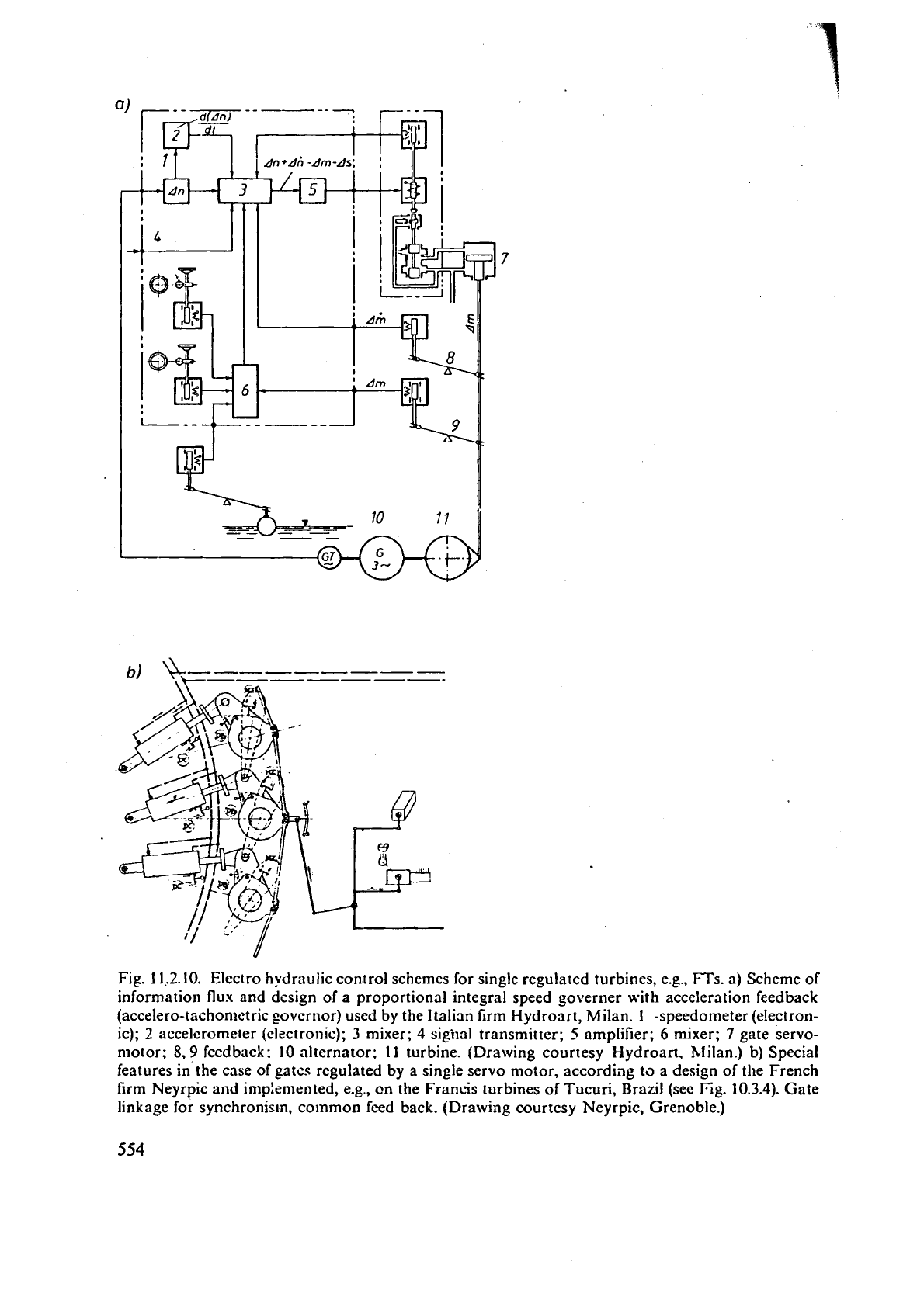
Fig. 1 l.2.10. Electro hydraulic control schemes for single regulated turbines, e.g., FTs. a) Scheme of
information flux and design of a proportional integral speed
governer with acceleration feedback
(accelero-tiichonietric governor) used by the Italian firm Hydronrt, Milan. 1 -speedometer (electron-
ic);
2
accelerometer
(electronic);
3
mixer;
4
sigiial transmitter;
5
amplifier;
6
mixer;
7
gate servo-
motor;
8,9
feedback:
10
alternator; 1
I
turbine. (Drawing courtesy Hydroart, hlilan.) b) Special
features in the case of
gatcs regulated by a single servo motor, accordjag to a design of the French
firm
Neyrpic and imp:ernented, e.g.,
on
the Francis turbines of Tucuri, Brazil (see
Fig.
10.3.4). Gate
linkage for synchronism,
colnmon feed back. (Drawing courtesy Neyrpic, Grenoble.)
