Raabe J. Hydro power - the design, use, and function of hydromechanical, hydraulic, and electrical еquipment
Подождите немного. Документ загружается.

10,5.2.
Influence
of
bearings on shaft vibration
10.5.2.1.
General remarks
The rotor of the turbine and generator and the shaft are excited usually
by
rotating forces
due
to mechanical, hydromechanical and electrical unbalance of the rotor masses. in
consequence of misalignment during assembly, imperfect balancing or short circuit. The
system of shaft and rotor masses, which is
elnstically supported and damped by
the bearings, responds to these excitations by shaft oscillations with finite amplitude of
different kinds
[lo.
12
11.
flexural vibrations as the most obvious type of vibrations are considered now separately. 1.e.. for
the generator to work properly, vibration must not accelerate to levels at which it misht damage the
components, or reach such an amplitude as to cause wear or wiping off the bearing's white metal.
fie rotary system must be properly insulated from the stationary one, so as to avoid subjecting
it
to excessive stresses. These differing requirements tend to be in contrast, as a bearing system, which
limits shaft vibration tends to put greater forces on the foundations and vice versa.
The basic element of damping and elasticity between rotor and the foundation is the
oil film in the
bearings. As already stated, the general way to limit vibration amplitude, is to design the machine
so, that its lowest critical speed is greater than any possible
operatirlg speed (runaway). Hydraulic
units have considerable shaft stiffness and the masses are limited by electrical, mechanical and
governing requirements.
So any method of increasing the critical speed depends on the possibility of reducing the elasticity
of the guide bearings. In a very stiff system small values of
the amplitude
cf
shnit vibrations can
involve significant unbalanced stresses which can exert high forces on the foundations.
For these reasons the traditional criterion of creating a large difference between critical speed due
to shaft stiffness and the rotor masses and the working speed cannot be considered
as
an abscjlu~e
guarantee of safety.
It
is necessary to make
a
thourough analysis of the dynamic response of the rotor which takes into
account three parameters: unbalance, vibration amplitude and
the feature of the bcariugs. Sincc the
bearing box and its support are usually rather
stiff, as a minimum requirement of a good bearin:
design, the features of the bearings are reduced to that of the lubricating film in the gap bctwecn seat
and shaft.
10.5.2.2.
The spring rate
of
the film
of
lubricant
As a model consider two plane faces parallel to each other, at distance
y,
with an area
A.
The clearance is filled with a lubricant of bulk modulus
E,.,
the boundaries might be
completely leak proof. Expressing the spring-induced force
by
F
=
K
dy,
where
K
is the
spring rate and
Ay
the compression of clearance, and using the relation
(8.3-5)
as the
equation of state
of
the lubricant, the spring rate reads
Hence the stiffness of an oil film increases with decreasing
cleararlce
y.
Thus an oil
fila
loaded by an unbalance, by which the oil is squcezed out of the
gap,
becomes suddenly
more stiff than an unloaded film existing in a well balanced system.
10.5.2.3.
The
damping coefficient
of
the
lubricant's film
Imagine an oil-filled gap, length
I
in the flow direction, width
5,
clearance
J*.
Both the walls
of
this gap might be squeezed by a damping force
F,
with the clearance rate
I;..
Hence by
definition the damping coefficient
d
=
&/j.
-This
sclrlcezing ;~ctui~res
a
prcssurc
Ap
which
presses the oil out of thc grip in the
stre;~mwise dirccr~on. It.ngtli
I,
kvitll
thc avcrnsc spcctl
c.
To bal:il~cc ti~c will1 shear stress
7:
dp
-
~l/y.
Nz)\l~~r's
law rcquires
7
-
tlc/y.
Continuity rcquires
c
-
j//y.
Wit11 Ap, the
dninping force becomes
F,
-
Aplb
--
z12b/y
-
rlc12b/y2
-
t~yI'h/y'-
dy.
Reducing
j
yields the damping cocflicient of the film
b
might' be the axial length of a journal bearing and
I
the
circumferential
length of its
loadcd face,
)I
the clearance of its gap. Hencc the damping coefficient of
a
bearing with
an unbalanced load, squeezing the oil out of the
gap, increases with decreasing clearance,
whereas the damping coefficient of a balanced system is nearly zero.
10.5.2.4.
Control
of
bearings
Regular working of a large hydroelectric unit
reql~ires
a
continuous measurement of
amplitudes due to shaft vibration to be installed,
e.g., at the bearings of the rotor. Such
a
measuring set consists of vibration transducers, signal amplifier and an indicator
and
rocording device with an appropriate alarm and locking signal. In this way
it
is possible
to intervene
quicklj in the case of alteratioli in the dynamic balance of the unit, caused
by
~nomalies (short circuit, bearing wear) and also to forecast the need for any normal
or emergency
maintainance,
[LO.
1211.
10.5.3.
nearing
design
and arrangement
10.5.3.1.
General remarks
In consequence of their size and load, particularly in the axial direction the bearings of
larger sets are only of the sliding type. Moreover the
12/licllell
tilting pad bearing type is
used exclusively for the axial
load, composed of hydraulic axial thrust and the weight of
rotating parts
in
the case of vertical shafts. For shaft diameters above about
1,5
m this
bearing
type is also preferred for the radial (guide) bearing.
Any bearing has to transmit a certain heat flow through its casing into the supporting
structure towards the foundations. This originates partly from
tlie waste heat of the
alternator
(in
the case of a bearing due
to
the latter) and partly from the bearing itself.
Fig.
10.5.4.
Principal bearing
arrangements. a)
2
Radial bear-
ings, both
'
the rotors of
overhung design, thrust bearing
on the head cover.
b)
3
Radial
bearings, thrust bearing on the
pit. Variants: middle or
upper
radial bearing omitted.
c)3
Radial bearings, thrust bearing
or? the generator stator.
several designs have been proposed to avoid additional stresses in this structure due to
thermal expansion. One solution consists in radial arms transmittins any radial expan-
sion via strongly prestressed springs into the concrete of the pit wall.
Another solution uses arms which are slightly inclined to the radius, so-called "skew
spokes", [lo. 173). Thus heat expansion of these arms is converted into a central rotation
of
the bearing casing about its axis. Thereby the skew spokes are subjected
to
bcnding.
With the largest heat expansion of the bearing's support, the clearance of a radial bearing
must not fall short of the prescribed threshold.
Fig. 10.5.4 shows typical bearing arrangements of hydro turbo generators with vertical
shaft. To this typical bearing arrangements
of
horizontal sets have to be added. See
Figs.
3.4.1; 3.4.19; 3.4.20; 3.4.22; 3.4.23; 3.4.28; 3.4.33; 10.2.10 to 10.2.18.
10.5.3.2.
Guide bearings
Usually two guide bearings are used, as their load is statically determined. Overhung
design is preferred at the turbine runner especially in reaction turbines. This keeps the
draft tube bend free of any obstruction by the shaft. In some ternary pumped-storage sets
the runner can be disconnected either from the alternator-motor (Fig.
3.4.38) or from the
pump (Fig. 3.4.39). This requires two guide bearings on both sides of the runner. This
holds also for rarely found double flow
FTs with a twin runner supplied by one spiral
casing.
The relatively big alternator rotor has an overhung design only up to heads
of
about
250m
and for vertical sets. In this head range the umbrella or semi-umbrella type of
alternator rotor prevails (Fig.
10.5.4a). Above this head the alternator rotor is supported
at
both ends (Fig. 10.5.4b).
In
the high-head range the two and three bearing arrangement is used. In smaller low
head sets with submerged turbine also three or more bearings are found, to make the
generator easily accessible and to place it above the tail race level.
The lubrication of the bearing requires the existence of
wedge-fonned clearances between
shaft and bearing sleeve in the order of
0,5
.
times the shaft diameter [10.174]. To
take out-of-balance loads like the magnetic pull the radial support of the bearing must
be
of solid design in all radial directions.
10.5.3.3.
Tllrust bearing
design,
brake
Vertical sets, especially of higher head, with axial thrust downward oriented, need only
one thrust bearing
(Fig.
10.5.2). Horizontal sets need two (Figs. 10.2.10; 10.5.5). For the
brief
and small reversed axial thrust in vertical sets during transients in KTs,
a
thrust
collar is provided. This is usually on the lower extremity of the bell-shaped part
of
the
shaft that is immersed in an annular oil tank, to facilitate lubrication of guide bearing
during starting (see Fig. 10.5.6).
The clearance of the surge face pad on the lower front of the guide bearing casing must
be
in thc order of the axial deflection which may be experienced under axial thrust.
For heads up to 320 m (Fig. 10.5.4) the thrust bearing is underneath the alternator and
then
supported either by a spider oil the pit wall or a supporting truncated cone on the
kid
cover (Figs. 10.5.4a; 10.5.4 b). In small sets and under highest heads, e-g., in PTs the
firust bearing rests on the generator stator by means of a spider (Fig. 10.5.4~).
Ie'ig.
10.5.5.
Guide bearin
two
;lxi;11
(thrust) bearin
c.g.,
n
T;T
with liorizonta
Oil circulation of thc t
bcaring
by
a
pulnp
feed
ring pipc 12, with radial
chcs, blowinl: out
the
oil agai
thc rotating thrust collar
1
a
starting
lift
by prcssurizc
from the bore 25.
1
r
thrust collar,
2
tilted
3
prop with calotte to sup
pad,
callote pressed
in
ml
iron ring,
5
spaccr
cage
of
pads,
6
pcdcstal of bcaring, cast iron,
7
drivcr for
1,s
oil level,
9
shah
10 split support ring,
11
fast-
ening ring for
10,
12 pipe con-
nection for fresh oil,
13
injection
pipe,
15
oil
pan, 16 ovcflow
edge, 20 bearing sleeve, 25 bore
for prcssurizcd oil during Start.
For an overhung alternator rotor the accessibility of the thrust bearing
may
be facilitated
by a removable ring, connecting the upper
end of the shaft with the upper front face of
thc rotor (Fig. 10.2.1). Tliis ring then serves as a thrust collar, which transmits the axial
thrust from the shaft tc the tilted segments.
For a revision, both the rotors must be supported by other devices,
e.g., the generator
brake, then used as jack. Then after removing the connecting bolts and the ring the tilted
pads become easily-accessible.
Each pad may be supported by springs or it rests on a radial edge or a spherical calotte
which presses
in
a ring of mild steel (Fig. 10.5.7). The pad may be supported also by a
pressurized plunger piston in an elastic
toroidal shell, supplied from a common oil
pressure vessel, under the controlled pressure of all the pads together, Fig.
10.5.8 [10.134].
At heads above about
1000
In,
a water-lubricated hydrostatic thrust bearing, at the lower
end of the shaft, reduces the tip diameter of this
besring and the corresponding disk
friction loss
[10.135]. This follows from the head-conditioned pressure, high
if
compared
with the mean
value of about 35 bar, which is attainable in the gap of a tilted pad, (see
Fig.
10.5.9).
In large units the elastic and thermal deformation of thc pad face from its desired plane
form is sometimes automatically compensated
by
meails of
a
special construction
[10.133]. Thus the centre of pressure distribution at the shoe is always retained.
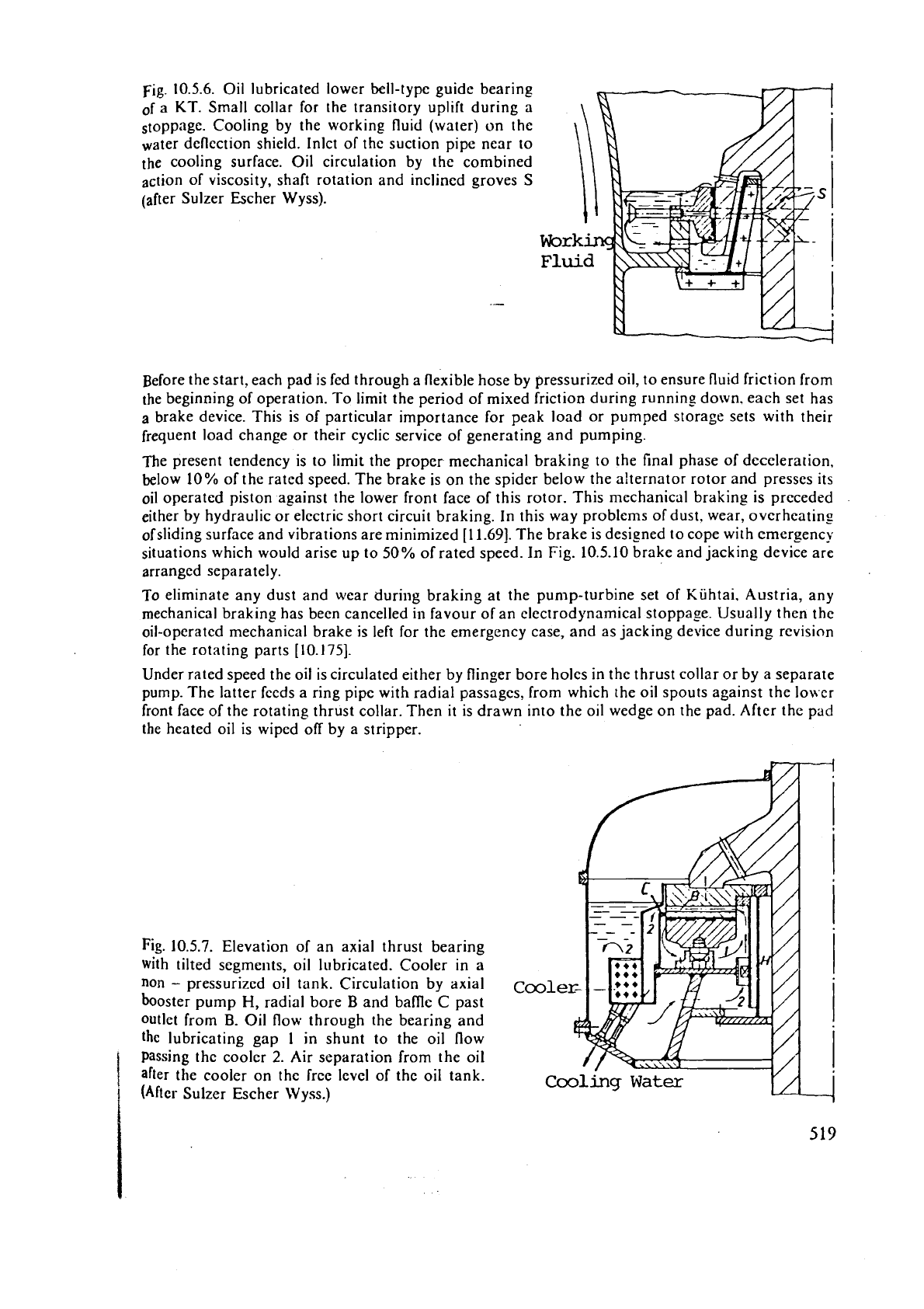
Fig.
10.5.6. Oil lubricated lower bell-type guide bearing
of a
KT.
Small collar for the transitory uplift during a
o top page.
Cooling by the working fluid (water) on the
water deflection shield.
lnlct of the suction pipe near to
the cooling surface.
Oil circulation by the combined
&on of viscosity, shaft rotation and inclined groves
S
(after Sulzer Escher Wyss).
.-
Before the start? each pad is fed through a flexible hose by pressurized oil, to ensure fluid friction from
the beginning of operation. To limit the period of mixed friction during
runnins down, each set has
a
brake device. This is of particular importance for peak load or pumped storage sets with their
frequent load change or their cyclic service of generating and pumping.
The present tendency is to limit the proper mechanical braking to the final phase of deceleration,
below 10
%
of the rated speed. The brake is on the spider below the alternator rotor and presses its
oil operated piston against the lower front face of this rotor. This mechanical braking is preceded
either by hydraulic or electric short circuit braking. In this way problems of dust, wear,
overheatins
ofsliding surface and vibrations are minimized
[11.69].
The brake is designed to cope with emergency
situations which would arise up to
50%
of rated speed. In Fig. 10.5.10 brake and jacking device are
arranged separately.
To eliminate any dust and wear during braking at the
pun-lp-turbine set of Kiihtai. Austria, any
mechanical braking has
been cancelled in favour of an electrodynamical stoppase. Usually then the
oil-operated mechanical brake is left for the emergency case, and as jacking device during revision
for the rotating parts
[10.175].
Under rated speed the oil is circulated either by flinger bore holes in the thrust collar or by a separate
pump. The latter feeds a ring
pipe with radial passages, from which the oil spouts against the !o\ser
front face of the rotating thrust collar. Then it is drawn into the oil wedge on the pad. After the pad
the heated oil is wiped off by a stripper.
Fig.
10.5.7.
Elevation of an axial thrust bearing
with tilted segments, oil lubricated. Cooler in a
non
-
pressurized oil tank. Circulation by axial
booster pump
H,
radial bore
B
and bamc
C
past
outlet from
B.
Oil flow through the bearing and
the lubricating gap
I
in shunt to the oil flow
Passing the cooler
2.
Air separation from the oil
after the cooler on the free level of the oil tank.
(After Sulzer Escher Wyss.)
Cool
Cooling
Water
Ill
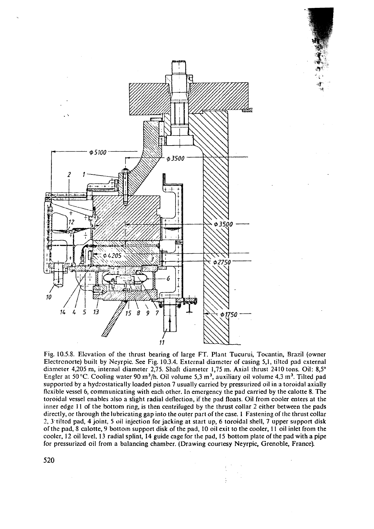
Fig. 10.5.8.
Elevation
of the thrust bearing of large FT. Plant Tucurui, Tocantin, Brazil (owner
Elcctrcnorte) built by Neyrpic. See Fig. 10.3.4. External diamster of casing
5,1,
tilted pad cxter~al
dinmetcr 4,205 m, internal diameter 2,75. Shaft diameter 1,75
m.
Axial thrust 2410 tons. Oil: 8,5"
Er.gler at 50 "C. Cooling water 90 m3/h. Oil volume 5,3
m3,
auxiliary oil volume 4,3
m3.
Tilted pad
supported
by
a hyd;ostatically loaded piston 7 usually carried
by
pressurized oil in a toroidal axially
flexible vessel
6,
communicating with each other. In emergency the pad carried by the calotte 8. The
toroidal vessel enables also
a
slight radial deflection,
if
the pad floats. Oil from cooler enters at the
in!ler edge 11
of
the bottom ring, is then centrifuged by the thrust collar
2
either between the pads
directly, or through the lubricating gap into the outer part of the case.
1
Fastening of the thrust collar
2,
3,ti!tcd pad,
4
joint.
5
oil injection for jacking at start up,
6
toroidal shell, 7 upper support disk
of the pad,
8 calotte,
9
bottom support disk of the pad,
10
oil exit to the cooler, 11 oil inlet from the
cooler,
12
oil level.
13
radial splint,
14
guide cage for the pad,
15
bottom plate of the pad with
a
pipe
for pressurized oil from a balancing chamber. (Drawing courtesy Neyrpic, Grenoble, France).
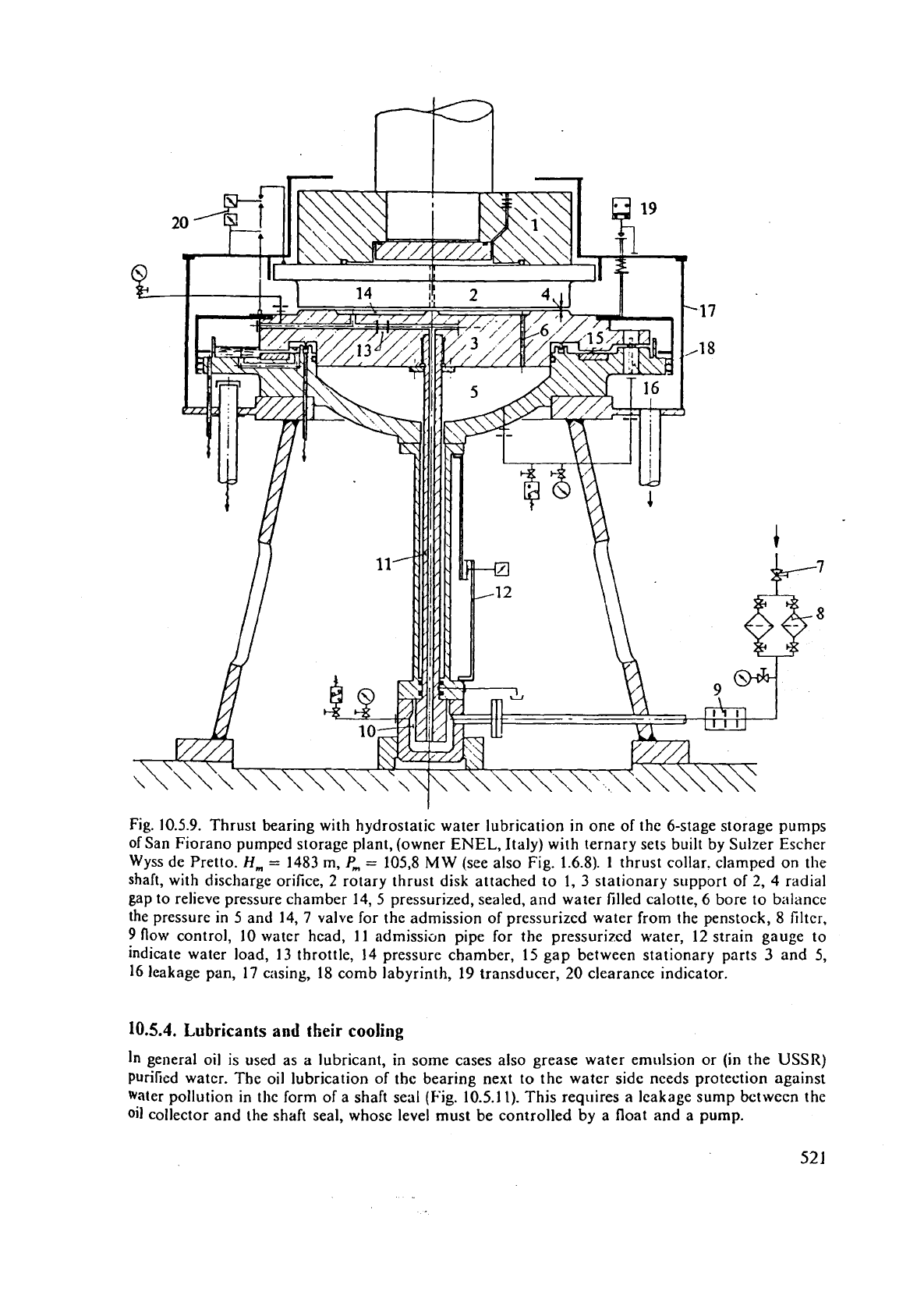
Fig. 10.5.9. Thrust bearing with hydrostatic water lubrication in one of the 6-stage storage pumps
of San Fiorano pumped storage plant, (owner
ENEL,
Italy) with ternary sets built by Sulzer Escher
Wyss de Pretto.
H,
=
1483
m,
P,
=
105,8
MW
(see also Fig. 1.6.8). 1 thrust collar, clamped on the
shaft, with discharge orifice,
2
rotary thrust disk attached to 1,
3
stationary support of
2,
4
radial
gap to relieve pressure chamber
14,s pressurized, sealed, and water filled calotte, 6 bore
to
balance
the pressure in
5
and 14,7 valve for the admission of pressurized water from the penstock,
8
filter,
9
flow control, 10 water head,
11
admission pipe for the pressurized water, 12 strain gauge to
indicate water load,
13
throttle,
14
pressure chamber, 15 gap between stationary parts
3
and 5,
16 leakage pan, 17 casing, 18 comb labyrinth, 19 transducer, 20 clearance indicator.
10.5.4.
Lubricants and
their
cooling
In
general oil is used as
a
lubricant, in some cases also grease water emulsion or (in the USSR)
Purified water. The oil lubrication of the bearing next
to
the water side needs protection against
Water pollution in the form of a shaft seal
(Fig.
10.5.1
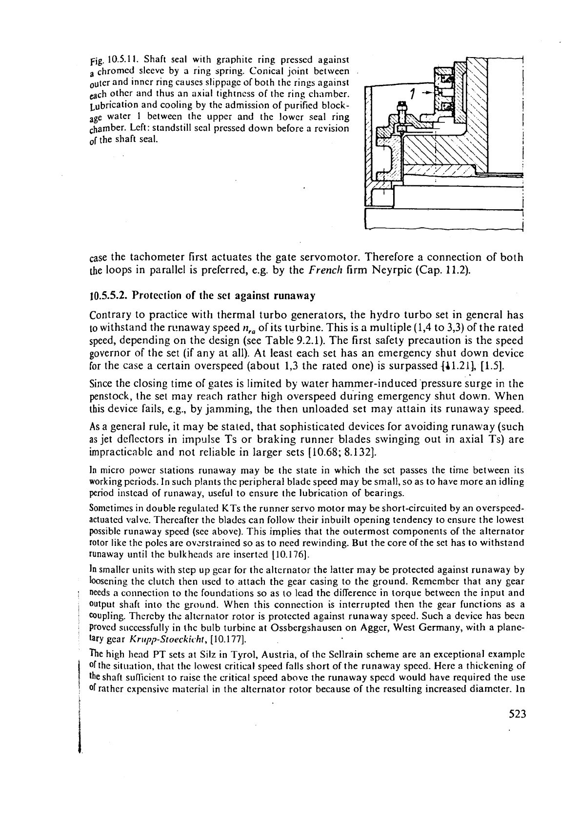
I).
This requires
a
leakage sump between the
oil collector and the shaft seal, whose level must be controlled by
a
float and a pump.
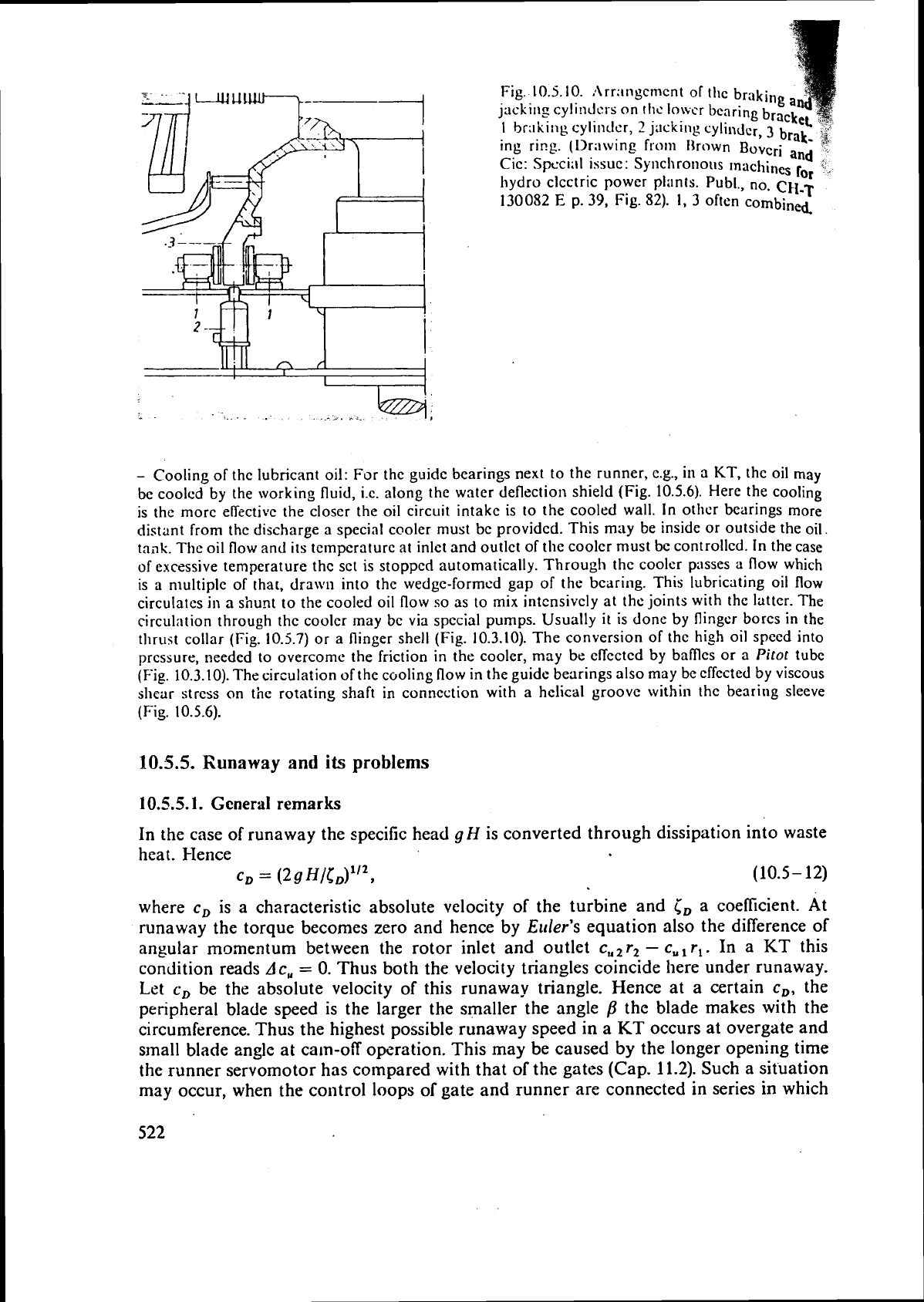
Fig.
10.5.10.
:\rr:lngcnlcnt
of
thc braking
jacking cyli~~dcr-s on
tI1~
lowcr bcnring brae
1
braking cylinclcr,
2
jacking
cylinder,
3
b
ing ring. (Ur;twing fronl Hrown Bovcri
an
Cic: Spcci;ll issue: Synchronous lnachines
14
hydro clcctric power plilnts. Publ., no.
CH-T
130082
E
p.
39,
Fig. 82). 1,
3
oftcn combined
-
Cooling of the lubricant oil: For the guidc bearings next to the runner, c.g., in
a
KT, the oil
may
be coolcd by the working fluid, i.e. along the water deflection shield (Fig. 10.5.6). Here the cooling
is the more effective the closcr the oil circuit intake is to the cooled wall. In othcr bearings more
distant from thc discharge
a
special cooler must be providcd. This may be inside or outside the oil
tailk. The oil flow and its temperature at inlet and outlet of the cooler must bc
controlled.
In the case
of excessive temperature
the sct is stopped automatically. Through the coolcr passes a flow which
is a multiple of that,
drawn into the wedge-formed gap of the bearing. This lubricating oil flow
circulates
in
a
shunt to the cooled oil flow so as to mix intcnsivcly at thc joints with the latter. The
circulrition through the coolcr may bc via special pumps. Usually
it
is donc by flinger bores in the
thrust collar (Fig.
10.5.7)
or
a
flinger shell (Fig. 10.3.10). The conversion of the high oil speed into
pressure,
needed to overcome the friction in the cooler, may be effected by baffles or a
Pitot
tube
(Fig. 10.3.10). The circulation of the cooling flow in the guide bearings also may be effected by viscous
shear stress
on
the
rotating shaft in connection
with
a
hclical groove within the bearing sleeve
(Fig.
10.5.6).
10.5.5.
Runaway and
its
problems
10.5.5.1.
General
remarks
In the case of runaway the specific head gH is converted through dissipation into waste
heat. I-Ience
CD
=
(29HlcD)1i2,
(10.5-
12)
where
c,
is a characteristic absolute velocity of the turbine and
i,
a coefficient. At
runaway the torque becomes zero and hence by
Euler's
equation also the difference of
angular momentum between the rotor inlet and outlet
c,,
r,
-
c,
,
r,. In a
KT
this
condition reads
Ac,
=
0.
Thus both the velocity triangles coincide here under runaway.
Let
c,
be the absolute velocity of this runaway triangle. Hence at a certain
c,,
the
peripheral blade speed is the larger the smaller the angle
B
the blade makes with the
circumference. Thus the highest possible runaway speed in a
KT
occurs at overgate and
s~nall blade angle at cam-off operation. This may be caused by the longer opening time
the runner servomotor has compared with that of the gates (Cap. 11.2). Such a situation
may occur, when the
co~ltrol loops of gate and runner are connected in series in which
~ig.
10.5.1
1.
Shaft seal with graphite ring pressed against
a chromed sleeve by a ring spring. Conical joint between
and inner ring causes slippage of both the rings against
@ch other and thus an axial tightness of the ring chamber.
Lubrication and cooling by the admission of purified block-
age water
1
between the upper and the lower seal ring
&amber. Left: standstill seal pressed down before a revision
of
the shaft seal.
case the tachometer first actuates the gate servomotor. Therefore a connection of both
the loops in parallel is preferred, e.g.
by
the
French
firm Neyrpic (Cap. 11.2).
10.5.5.2.
Protection
of
the set against runaway
Contrary to practice with thermal turbo generators, the hydro turbo set in general has
to
withstand the rimaway speed
n,,
of its turbine. This is
a
multiple (1,4 to 3,3) of the rated
speed, depending on the design (see Table
9.2.1). The first safety precaution is the speed
governor of the set (if any at all). At least each set has an emergency shut down device
for the case a certain overspeed (about 1,3 the rated one)
is
surpassed {41.21],
[IS].
Since the closing time of gates is limited
by
water hammer-induced .pressure surge in the
penstock, the set may reach rather high overspeed du'ring emergency shut down. When
this device fails,
e.g., by jamming, the then unloaded set may attain its runaway speed.
As a general rule,
it
may be stated, that sophisticated devices for avoiding runaway (such
as
jet deflectors in impl~lse Ts or braking runner blades swinging out in axial Ts) are
impracticable and not reliable in larger sets
[10.68; 8.1 321.
In
micro power stations runaway may be the state in which the set passes the time between its
working periods. In such plants the peripheral blade speed may be small, so as to have more an idling
period instead of runaway, useful to ensure the lubrication of bearings.
Sometimes in double regulated
KTs the runner servo motor may be short-circuited by an overspeed-
actuated valve. Thereafter the blades can follow their
inbuilt opening tendency to ensure the lowest
possible runaway speed (see above). This implies that the outermost components of the alternator
rotor like the poles are
ovzrstrained so as to need rewinding. But the core of the set has to withstand
runaway until the bulkhcnds are
insertcd
[10.176].
In
smaller units with step up gear for the alternator the latter may be protected against runaway by
loosening the clutch then used to attach the gear casing to the ground. Remember that any gear
needs a connection to the foundations so as to lead the difference in torque between the input and
output
shafr into the grobnd. When this connection is interrupted then the gear functions as a
:
coupling. Thereby thc alternator rotor is protected against runaway speed. Such a device has been
Proved successfully in thc bulb turbine at Ossbergshausen on Aggcr, West Germany, with a plane-
tary gear
Knrp13-Stoeckic.hr,
[10.177].
Thc
high head PT sets at Silz in Tyrol, Austria, of thc Sellrain scheme arc an exceptional example
ofthe sit~~ation, that the lowest critical speed falls short
of
the runaway speed. Here a thickening of
the
shaft suflicient to raise the critical speed above the runaway specd would have required the use
!
of rather expensive material in the alternator rotor because of the resulting increased diameter.
lo
sucll
n
caw, carc must be taken, th,it undcr all imnglnnblc opcr;~tions thc fundway spccd ncvcr
I\
co~ncidcq nit11 the critical SPI-C~.
Tlic
I:~ttcr
IS
only p:lsscd dur~ng running tl~\!~n or 5pccdrng
up.
I11
two rcccrltly buiit scts
with
Isogjrc punlpturbincs, Grimscl. Swirzcrl;~nd, Fig.
3.4.3,
and lZ/laltn,
upper stagc, Austrin, Fig.
1.6.7,
[I
1.70;
10.1
161,
thc lowcst critical spccd f;~lls short of runaway -\pc~d.
This may
bc
a rcasonnble practice,
if
the runawily spccd dcviates from thc lowest critical speed ulldcr
all
possiblc modcs ol
operation.
Howcver, for the Malta set this is iiot
assured,
as the scts opcratc with a largc variation in
head
:l,,d
runaway
speed
so
as
to tlccd, by thc way, also a cl~unge polc
alternator.
Hcncc thc critical speed
occasionnl!y may coincide with thc runaway spccd. In this case all thc cmcrgcncy shut down devices,
like
govciiior, ovcrspced governor, valves and gates must opcratc safely.
10.6.
The
comyrltation of
flow
in
a
Francis
runner
10.6.1.
Flaw
prediction for
given
runner and working data
10.6.1.1.
Introduction
This section is considered to be supplementary to the simplified runner design of a
FT
ii~ Cap. 10.3.6, which may be used as a preparation. In the following the problem is
treated of the distribution of relative velocity in
a
given runner vane channel under given
flow
rate with respect to face to face and shroud to hub distribution even with regard to
loss
and a slight twist of the streamface within the runner channel.
10.6.1.2. Assumptions
Consider the runner of a FT (Fig. 10.6.1) with given geometry under known working data
y
II,
Q
and
11
(o)
around the bep. The flow does not stall and is steady. The absolute
flow
is irrotational. Thus the axisymmetric flow pattern
in
the mcridian gained by the net work
mcthod due to potential flow, Cap.
5.2,
is taken
as
a first approximation. From this
stepwise approximation may be made to the real streamline pattern.
The
pheliome~ia at the ends of a vane'are neglected. Hence the flow is along the vane
surfzce. The flow is treated on a surface with coordinates
a
and
cp
(Fig.
10.6.2). The
azimuthal direction
cp
is peripherally orientated. It coincides with the sense of the angular
velocity
o
of the runner. The a-lines are oriented liom the shroud towards the hub and
follow at leas! on the runner vane face the direction of the latter. They make an angle
n/2
-
v
with the periphery (Fig. 10.6.2a). They coincide (Fig. 10.6.1.2) on the runner inlet
and outlet with the axisymmetric surfaces
2
and 1, touching the inlet and outlet edge
2
and 1 of the runner vane. The other axisymmetric surfaces that contain the a-lines vary
conti~iuously in streamwise direction between these faces
2
and
1
at the extremity of the
rotor vane passage.
The projections of the a-lines in the local meridian, denoted by
a',
make an angle
9
with
the local
rzdius
r
(Fig. 10.6.1.1). The a, cp-face has the advantage, that it neither intersects
the
axisym~netric faces
2
and
1
touching the extremities of the runner vanes, nor the
runner vane itself, when proceeding along a direction from shroud to hub or when
proceeding in the cp-direction from the suction face to the pressure face of the vane. With
this system the blockage
of
the flow passage by the vane and its boundary layers must
be accounted for by an adequate contraction coefticient.
