Raabe J. Hydro power - the design, use, and function of hydromechanical, hydraulic, and electrical еquipment
Подождите немного. Документ загружается.

I,,
front of the observer the fluid enters the
wave
front with ceierity
a.
Hence the influx
of
nlass into the shock plane is:
rn
-
Q
Aa.
To
employ mass conscrvntion im;~ginc the
front to bc a fluid
lamina with infinitesimally small thickness in the direction of thc
axis. The mass flow leaving this 1;1mi1ia is:
lii
+
d1i1
=
Q
An
+
d(p
Arr)
Mass conser-
vntion requircs
dri~
=
0
or
d(~
Aa)
=
Audg
+
q(10A
+
QA
du
=
0.
Since the celerity
a
is a constant figure, the problem rises
if
'do'
must be cancelled or not.
,-lere the following consideration helps.
As
above mentioned, also the velocity ol the fluid
,("ow assumed as zero) is
subjected
to a stepwise incremellt
dc
within the wave front. As
the celerity of
a
fluid is relative to the fluid, now tile celerity within the wave front
,speriences
a
stepwise change that equals
dc.
Hence
da
=
dc.
~~eping this in mind the mass conservation and the momentum equation for the moving
observer read
:
d(eaA)=O
or
~Adc+aAclg+~adA=O, (8.3
-
1)
Elimination of
dc
gives the celerity as
a
=
[deldp
+
(@/A)
dA/dp]
-
'1'
Obviously this relation holds good for
a
pipe with arbitrary cross sectional area
A,
.
constant along the pipe axis.
~pplication of
(8.3-3)
to a cylindrical pipe: Now
A
=
(n/4)
D2,
dA
=
2(n/4)
DtlD.
Ob-
viously the increment
of
tangential strain
ds,
=
dD/D.
l-looke's law for
a
one-dimensional
state of stress
in the pipe wail, modulus
of
elasticity Ef, reads
E,
=
o,/E1,
(8.3
-
4)
where
E,
is the tangential strain,
a,
the tangential tensile stress. Obviously
dD
=
D
rlc,
and
with
(8.3-4)
and the equilibriun~ on the thin-walled pipe,
a,
=
pDl(2
s)
(Fig.
8.3.1
b),
dD
=
D2
dp/(2
s
E') and
dA
=
A
(D/s)
dp/E1.
This reduces the second term in
(8.3
-
3)
to
(CIA) nnld~)
=
(PIE') (Dls).
The firsi term in
(8.3-3)
follows from the equation of state
=
el&,.
(8.3
-
5)
With the above, the celerity of
(8.3-3)
is converted into
a
=
{e
[l/E,
+
(1
/El)
(D/s)]}
-
'I2
.
The one-dimensional state of stress according to
(8.3-4),
in which
E'
corresponds to the
real modulus of elasticity of wall material, exists in a pipe, that is supported at both its
cnds
by
a frictionless stuffing box. When the pipe is closed at one of its ends, but can freely
cxpand there, then
E'
is related to the rxl value
E
by:
E'
=
E/(1
-
m/2)
with
HI
=
0,3
as
Poisson's ratio. In the case, the pipe is axially fixed at both its ends:
E'
=
E/(l
-
m2),
(see
also
[8.83; 8.851).
In general E' depends on the support of the pipe.
-
I'rovisional nieasurement of the celerity: Imagine
a
penstock, whose length is
I,
between its
shut
valve at the lower end and its
uppcr
end, usually open into a head reservoir or surge tank.
Any
instantaneous reduction of the valve's cross sectional area by a corresponding adjustrncnt induces
a
Pressure wave, which propagates
with
celerity
'a'
towards the uppcr end
(Fig.
8.3.2
a and
b).
There
it
is
rcflccted as a ncgativc prcssure wave. With
the
so-called reflection time
T,
measured by the
inllication of a manometer, elapsed since the intentional sudden throttling of valve, the celerity yields
a
=
2
LIT,.
(8.3
-
7)
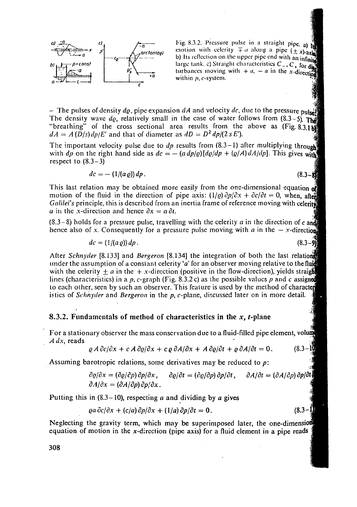
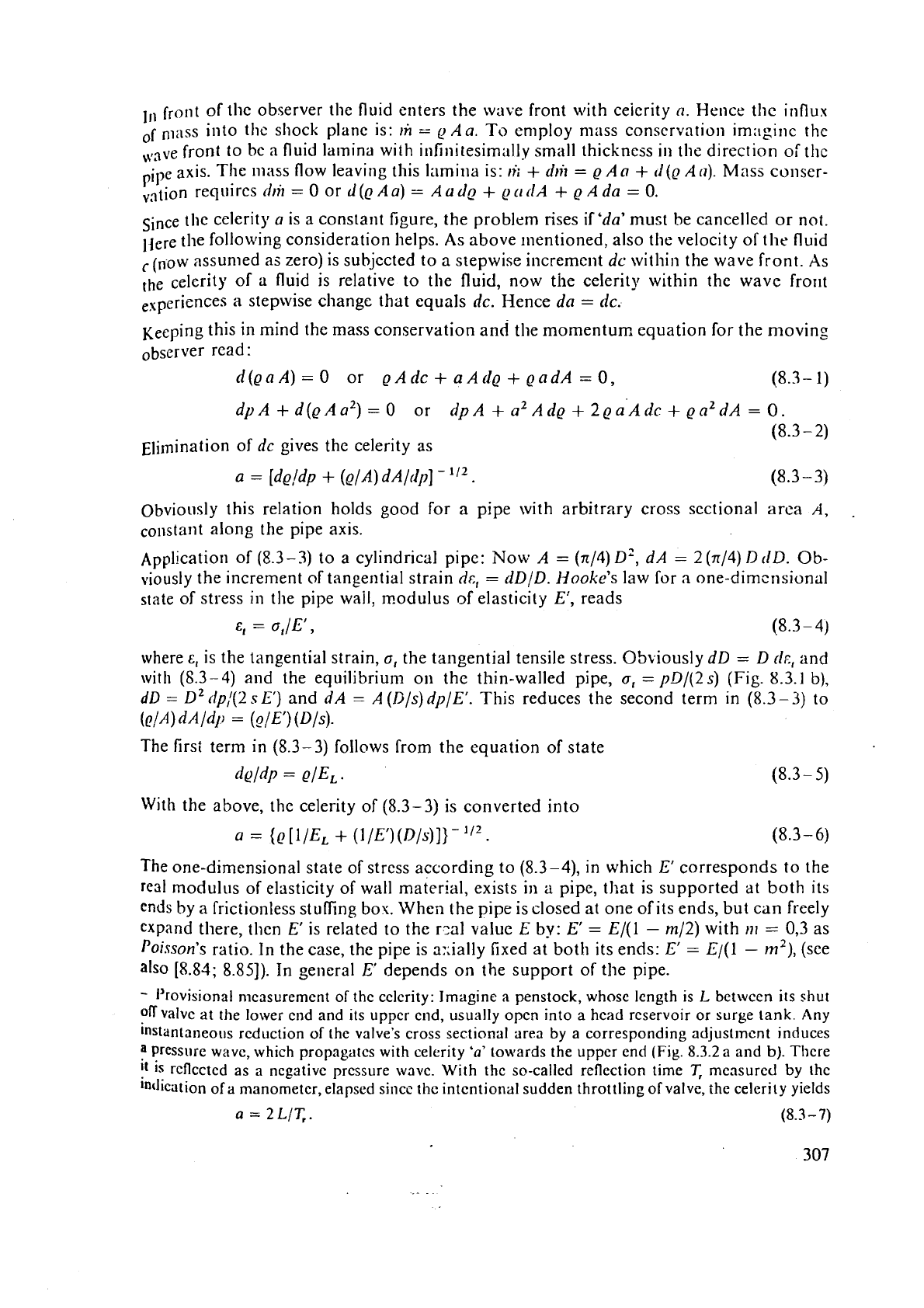
Fig.
8.3.2.
t'rcssurc pi~lsc
in
n
straigh
&;;
%%-
~:lotion will~ cclcrity
T
ti
alo~~g
a
-6-
-
---
b)
Its ~cIlcct~on on thc uppcr
pip~
cn
p=const
Inrgc
tank.
c)
Straight chnractcristics
C-
bJ
--
turb;inccs rnovillg with
+
u,
-
a
iu
th
--
-
a
within
p,
c-system.
0
i----L
C
-
?'he pulses of density dg, pipe expansion rlA and velocity dc, due to the pressure
The density
wrtvc
d~,
relatively small in the case of water follows from (8.3-5).
"breathing" of the cross sectional area results from the above
as
(Fig. 8.3.
d,4
=
A
(D/s)clp/E1 and that of diameter
as
(ID
=
D~
dp/(2
s
El).
The important velocity pulse due to dp results from (8.3-1) after multi
with dp on the right hand side as dc
=
-
(adp/e)[d~/dp
+
(~/A)d/l/tlp].
T
respect to (8.3-3)
dc
=
-
(1
/(a
Q)) dp
.
This last relation may be obtained more easily from the ox-dimensional squation
motion of the fluid
in
the direction of pipe axis: (l/e)i?p/c?x
+
dc/at
=
0,
when, aft
Galilei's principle, this is described frorn an inertia frame of reference moving with
celcri
a
it1
the x-direction and hence ax
=
a
dt.
(5.3
-
Sj
holds for a pressure pulse, travelling with the celerity
(1
in the dirzction of
c
a
hence also of
s.
Consequently for a pressure pulse moving with
a
in the
-
.Y-directi
dc
=
(
!
/(a
e))
dp
.
After Schnyder. [8.133] and Bergeron [8.134] the integration of both the last
under the assumption of
a
constant celerity
'a'
for an observer moving relative t
with
the
celerity
+
(I
in the
+
x-direction (positive in the flow-direction), yields
lines (characteristics) in a p,
c-graph (Fig. 8.3.2 c) as the possible values p
slid
c
to each other, seen by such an observer. This feature is used by the method of
istics of Sc.lrnyder and Bergerort in the p, c-plane, discussed later on in more detail.
8.3.2.
Ftlndamentals
of
method of characteristics
in
the
x,
t-plane
For a stationary observer the mass conservation due to a fluid-filled pipe element, volu
A
clx,
reads
A
zc/ax
+
A
ae/ax
+
a~la~
+
A
aelat
+
a~lat
=
o.
Assuming barotropic relations, some derivatives may be reduced to p:
anlax
=
(a~lap)
ap:ax.
Putting this in (8.3-
lo),
respecting
a
and
dividing
by
a gives
ea 6c/a-~
+
(cla) ap/ax
+
(l/a) apldt
=
0.
Neglecting the gravity term, which
may
be
superimposed later, the one-dimensi
equation
of
motion
in
the x-direction (pipe
axis)
for a fluid element in a
pip
308
,vJlere
r0
is the \l1all sllear, standing for the internal loss.
~dding both the last rclations and the11 multiplying by
'a
tlt' gives
The flow now is referred to a x+-coordinate system, moving relative to the flow with the
'u'
in the flow direction
(+
x-direction). This system has tile velocity
(rz
;
c)
rclati~e to a stationary frame of reference with coordinate
x.
Hence (Fig. 8.3.3
a)
The time elapsed
t
is counted from the instant, when x and x+ coincide. The line
x+
-
x+ (t)
(8.3
-
15)
is defined as the positive characteristic within the x+, t-system. The celerity
'0'
may
var)
dong the pipe axis, when
E'
or D/s changes. Hence, strictly speaking, the relalion (5.3-
14)
holds only for the time interval dt in the form
dx+ =(c+a)dt. (8.3-
I
6)
substituting this in (8.3-13) brings with ax
=
ax+, and then accounting for
tl~,
=
(dcli3x +)dx
+
+
(dc/?f) tlt and clp+
=
(8p/dx+)dx+
+
(d)/dt) dt, the
y,
c-characteristic
in the x
+
-system, now with the pipe loss, reads
As (8.3-8), but now referred to a real fluid with internal friction and moving in
the
+
x-direction with velocity c, the last relation conibines the pressure increment
rip,
and
rhc corresponding velocity increment
dc+
for an observer, moving with celerity
'u'rn
thc
t
x-direction-relative to-the fluid. Sirnilarily for
a*
observer,movini
with
celerity
'a'
rclative to the fluid in the
-
x-direction along the so-called negative characteristic
(scc
Fig. 8.3.3
a),
infinitesimally
defined by
the relation that now corresponds to (8.3-17) is taking the fonn
Assuming quasi steady flow, the wall shear stress
can
be reduced to the pipe loss coeffi-
cient
2
(see (5.4-
14))
by
Fig.
8.3.3.
Characteristics
in
the
x,
t-
plane.
a)
Characteristics
[+,
i-
in
the
x,
[-system of an observcr moving rela-
live
to the fluid, velocity
c,
with
cclerity
+
a,
-
a
in the x-direction. b) Applica-
tion of the characteristics-method
by
means of
a
prescribed
grid of points,
whose
state
(p,
c)
is
known, or to be
determined.
dl:
1,
-
t,,
t,
-
1,.
-X
--
cdl
,
cdt
odt
i
odt
-
Thus
(3
3
1
7,
(S.
10)
are
cor~vcrtcd irito
(I,,
,
+
,I
Q
11,.
,
=
-
,
[tr/(c
+
tl)] tls
,
[4(2
D)]
I
c
+
1
c
+
,
lrl)
-
==
[tll(c
-
U)
J
(1-u-
[i.i(2
1111
1
c
-
.
8.3.3.
Application
of
method
of
cllaractcristics in
s,
t-p!ane
Assume, that
u
it~ld
t
for the direrent stations
A,
B,
C
of a pipe are known a1
x, but
unknonin
nild required along the line x
+
Ax
(Fig. 8.3.3 b) in the charact
.u, r-plane.
I'hc
characteristics
[
+
,
<
_-,
as clefined by
(I\-,
=(c+a)clt=<,dt, Jx-=(c-o)dt=[-dt,
are known at the st:~tion
C,
but unknown at the stations on the line x
+
Ax. The
m
aim of the follo\ving cornput;~tio~~ is the determinrition of pressure p and correspond
velocity
c
xi
tilt.
station
P,
when
p
and
c
are known
at
the stations
A,
B,
C
and when
coordinates
of
I.'
in ;he
.u,
t-plane are fixed. It follows
de
Be~rzclrtiinis
et
al.
[8.99].
On the stations,
A,
B,
C
as subscripts are added to the variables. The characteris
c.-.
[+
through
the
~oint
P
intersect
Ihc
line
.u
at the stations
R
and
S.
From this
periods
t,
and
t,
follow by an extrapolation
as
(Fig.
8.3.3 b)
t,
=
-
,sp
-
+x,)/[+~
+
f,,
tS
-
-
(xp
-
xs)/Lc
+
fp.
With
~f.~jdt
=
9,
c+c=
dx/(tc
-
t,),
[-c
=
Ax/(tS-
te),
the values p,(.ps,
c,,
c,
result from
4
linear equations, written as follows in
ma
llotation
{:},=
k}c[l
-
tx;:1+
k}A8<i:,
("1
c
s
=
{:}c[l
-
lf9<-21+
~}B19c1:,
in ~vhich p,,
c,,
p,.
c,, p,, c, are known. With
p,,
p,, c,,
c,*,
the pressure p,
and
velocity c, follow by (8.3-211, (8.3-22) as
pP
-
pK
+
(I
g
(c,
-
c,)
=
-
{Q
a
A/[(cR
+
a) 2 Dl) lcRl cR (x,
-
x,),
(8.3-
pP-~~s+a~(~P-~S)
=-
{QaL/[(c,+ a)2Dl)lcsIcs(xp-xs).
Herein
s,,
x,, s,,
a,
p,,
c,,
cSs
and
iJ(2
D)
are known. Thus p, and
c,
can be dete
from the last two relations.
8.3.4.
The
celerity
in
a
two
phase
mixture
When the pressure falls short of its critical value, evaporation creates two phas
same
may also occur when the liquid, saturated with dissolved
gas,
passes a lo
zone. Here the gas
may
be released
so
as to have
a
two phase mixture.
In the following the prediction of the celerity
in
two phase flow is introduced accor
to
;l
method proposed by
Reclii
and Faiielli [8.97].
Assumptions: A liquid split into two phases, the one of which is both gaseous
vrlpour in its state, the other is liquid. The liquid is mixed with gas- and
v
bubbles, having the same ~Kective radius
R.
The following nomei~clature is used:p
310
P
ressure in the liquid phase.
17,
that in the gas, p,, that in the vapour phase.
y,,,
that of the
u,,,
is the spccilic volume of the mixture,
v,
and
I;
are
"specific
volun~es" of likcwisc.
gss~o~is and vnpour phase
(c,)
and the liquid phase
(1.)
each referred to the unit
of
n~:~ss
of
the
mixture. Hence the pressure of the mixture
For
stiffly assumed walls the celerity
a,
of the mixture
Contrary to the usrlal thermodynamic procedure, the absolute temperature
T
is assumed
,,
constant for 8v,/dpwl. This is in accordance with observations [8.97].
Additional assumptions:
,)
Gravity negligible, gas and vapour phase are uniformly distributed over
N
spherical
bubbles in the unit of mass of mixture, radius
R.
Hence the "specific volume" of the gas
phase
v,
=
(413)
n
NR3.
Thus
b)
The interface between gas and liquid has a surface tension
a.
This requires
p
=
pL,
+
pg
-
2
o/R. Hence
at
a
=
constant
dp
=
dp,,
+
dp,
+
(2
a/R2)
dR
.
(5.3
-
34)
c)
Gas and vapour follow the perfect gas law. Thus with
k
as gas constant and
M,
and
h4
the molecular masses of gas and vapour:
p,
=
k
p,
TIM,, p,
=
k
Q,
TIM. Hence
dp,
=
(kTIM) d~,
.
(8.3- 36)
d)
The
mass in each bubble is conserved. Thus
Q,
R3
=
const or
c)
The masses of liquid and vapour plus gas within the unit mass of mixture are con-
served. Hence
pv
+
e,,
c,
=
const or
Note that here
gt:
is not "one" but
kg
liquidlkg mixture.
f)
Pressure and density of the liquid obey
an
empirical equation of state. With bulk
modulus
EL,
n~
=
(QIEL)
d~.
(8.3
-
39)
g)
Liquid and vapour are in thermodynamic equilibrium. Therefore the chemical poten-
lids are the same. Hence for
T=
const:
e,dp
=
Q~P,.
(8.3-40)
n1e
followir~~ unknown
Xi
appear in the linear inhomogeneous system, represented by
(8.3-
33)
through (8.3-40):
Olict.
this
sjstcm
has
bccn
solvccl,
the celerit~. f~llows as
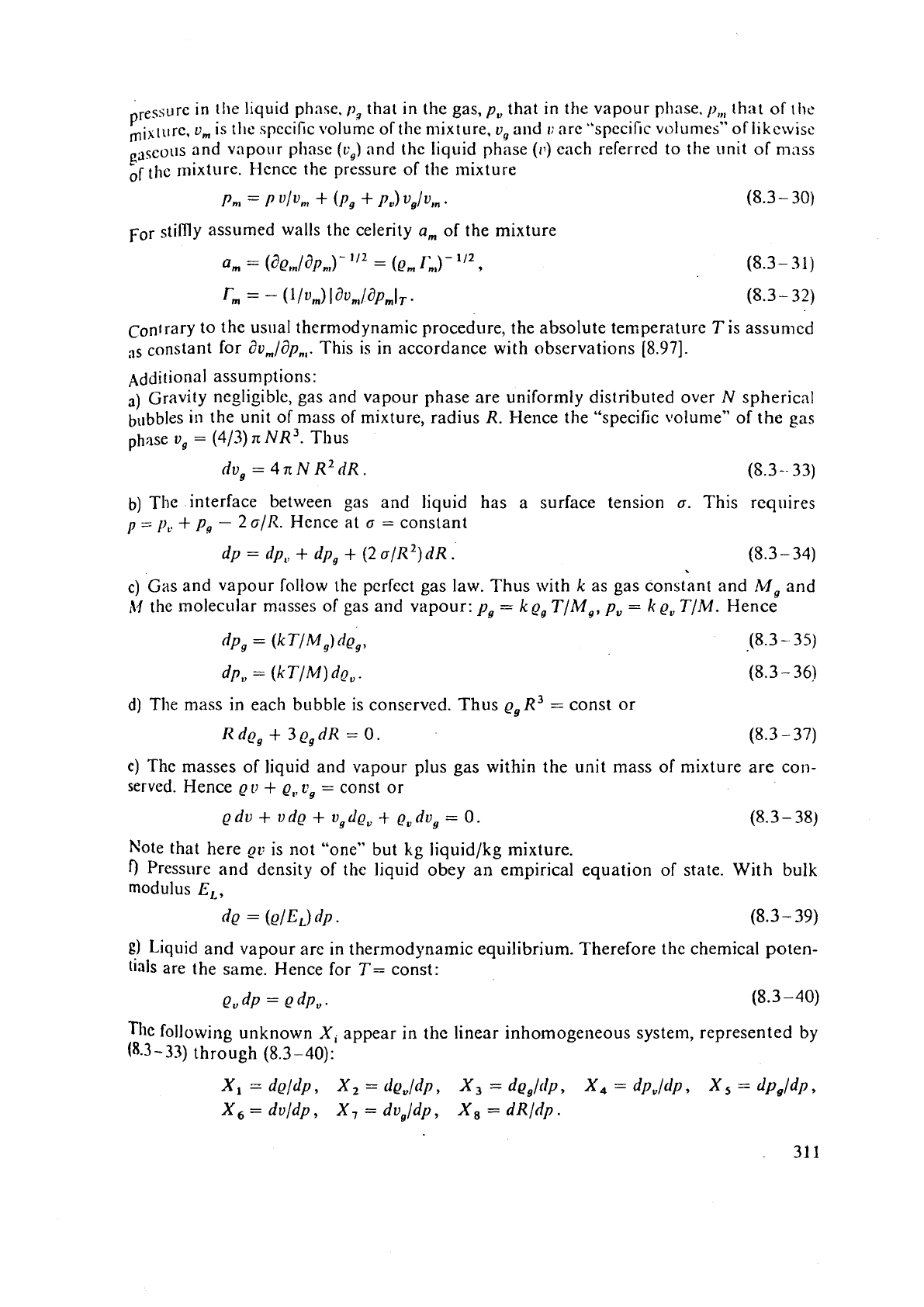
Typical examples of
a,,
can be scen in the
(1,
graph vs
x
at constan
x
depends on the void fraction
x
=
u,/u
by
x
=
log,,
V/II,.
Note
a
very small range of very small values
v,/u
(Fig. Y.3.4), which is
two-phase-flow
even
if
this gradient depends on the flow type, e
flow,
slug
flow,
stratified flow. See also [8.64;
8.981.
8.3.5.
Influence
of
evaporatiorl
and
diffusion
According to the last relation, the celerity of a mixture depends strongly on the
v
fraction, which contrary to the above section is now wri~ten in more detail as
(<
+
V,)/
where
V,
is
the gas part and
V,
the vapour part of the void volume, and
V,
the volu
of the mixture due to the void.
For a void with
impermeable walls, not subjected to gas diffusion and evaporati
void's volume and hence the void fraction depends on the pressure by an equa
stare. This may have the form
p(Y,
+
Ifu)''
=
const.
For
a
void, partly subjected to evaporation, or condensation, but not to diffusion,:
csponent
11
can be approximated after
Ranbe
[8.30]
by the molecular masses
hi,,
M
gas and vapour and the real masses of gas and vapour nl, and mu, contained within
average
void
considered
by
means of
n
=
1
i-
in,
l\/l
,/(m,,
M
,)
.
In the case of evaporation. the growth of the void is governed by the differential equa
of
liea
t
transfer
(8.2- 19).
The volurrle of a spherical void, radius
R,
that col~tains a gas mass
m,
and a vapour
in,..
at an absolute temperature
T
and the total pressure
p.
can be determined,
if
gas
vapour follow the behaviour of an ideal gas, and have the corresponding
gas
const
kg
and
k,.
Thus
v=
V,
+
=
(4/3)nR3
=
(k,m,
+
k,m,)T/p.
The increment
Atn,.
of the vapour mass
evaporation of the liquid, that surroun
heat
c,,
a density
Q
and
a
superheat
TL
within the thermal boundary layer
o
312
leqllired far evaporation. Hence, with a tliickness
4,/;;;
of ther~mal boundary
Iaycr
Ant,,
=
8
n
R'
cL
(ot)'I2
(T-
-
T)/A
.
The increment
dm,
of
E,as mass
by
diffusion during a certain time elapsed
t
can be
f~+om the supersaturation
C
-
C,
of the diffusion boundary layer, thickness
4fi,
n~ass dillusivity
D,
adjacent to the bubble wall, with dissolved gas. Hence
Am,
=
8
n
R2
(C
-
Co)(Dt)112,
&ere
C
is the gas mass dissolved per unit volume, existing in the instant
t,
and
C,
the
C
due to saturation, that follows from
Henry'
law
Co
=
const
p,
[8.6].
The rols
d
diffusion d~iring water hammer was highlighted by
Olderrziel
[8.35].
8.3.6.
Boundary conditions
in
the
p,
c-plane,
loss
influence
~t
the end of a pipe attached to
a
larger reservoir (surge tank), the pressure is given by
the elevation of the free water level above the pipe connection and hence is more or less
constant. Here, a positive pr-essure wave, that arrives at this station is rcfleztsd as a
nt.gative pressure wave.
When the pipe diameter changes in
stepwise manner, the pressure is the same for both
the adjacent parts of the pipe. In bifurcations, the pressure, which acts in each branch. is
the
samc. In bifurcations
and
at
a
station, with a change of the cross section of the
passage,
the ve!ocity must obey mass conservaticn with due respect to e~entuzl contrac-
tion or
lilllitcd diffi~sion. In the latter case the pressure acting on the adjacent branch must
be
diminished by the corresponding shock loss.
When the flow passes a special device or machine, pressure drop between inlet
and
ou tlct
of the device, and the mean velocity of the through flow, ha7;c to be related
10
each other
by
the characteristic of this devicc with a certain sense of thro:lghflow.
In
the case of a valve or the nozzle of a Pelton turbine this relation reads
where
k,
depends on the position of a regulating device (provided the apparatus has one).
In
a
PT
the pressure past the nozzle is constant. Hence the above relation yields the
pressure upstream of the nozzle or at the lower end of the penstock.
In reaction fluid machines the above pressure drop depends also on the speed
11
of the
machine. Thus the characteristics of the machine with
a
certain flow
c,,
at its bep, under
a
gate opening
a,,
in the case of
a
turbine is given
by
the following parabola-like function
Ap
=
--
ko
n'
+
(k,
+
k,
cot
a,)
11
c
+
k,
rl
(c
-
cop)'
+
k,
c2
+
kSn3
+
keep'.
(8.3
-47)
With the
ki
as design parameters, both the first terms are due to the change of whirl
velocity component in the rotor at a certain gate opening angle
a,,
the third term is due
10
thc shock loss at rotor in!et, the fourth
term
due to the loss in the flow passages, the
fifth term due to disk friction loss and the last term due to lc;~kage loss-
Once the pressure
at
the exit of the turbine is known from the elevation of tailwater above
the exit, then the pressure at the inlet of the turbine follows from the latter
and
Ap.
if
tllc
III:~(.II~~IC
II~IS
SI>CC~
~~c;~rri;ltio~i.
'111il
s1111pIi~s
;III
CICCII-i~
gild.
'11.
is i.~t;li~~~,j.
d1.11
it:g
sl:r~-L
\!I>
or
;II.~cI.
cli:,~.or~!ic~.ti~ig
I
iic
s~L
c1.0111
~IIC
C\(:~.[~IL
gl.i(!.
ll?~
spccll
11
v;,,.
this caw
tl~c:
;rngulat- :~c.cclcr;llion
tlc~),'tlr
its
;I
sc;~!c I.or-
tl11:
sl?ccd r.~tc
li
i.c:i~~lt~
fro
cclu;~tic,n
ol
motiot~
of
!IIC
set ivith its
1~1~m~ilI
of
iril:rti;l
(9
;11ic1
its evc1i111;11 excess
lo,.
:\,I
by nicilns of
R.1
=
O
dO)/,it
.
In thc c;isc
of
lvncl rejcctio~i tlic cxccss torquc
corresponds
10
that
of
the
machine
follo\vs Tro111 flow,
head,
efliciency
of
its inst;lntuncous tvorking point
(yH,
Qj
111
=
Q
Q
g111//0).
The
pressure
drop
A/)
ivi thili machines
01-
deviccs
(especially
vnlvcs) dcpentis als
internal loss. Tile lalter,
as
empirical
a:!rurn,
is
only
known frcm stationary tests.
same
h<)l<ls also
Tor
the pipc loss cocft!uie~it.
2..
'This innut-nces
thc
prcssure
I?+
;.I
(5.3-21)
on the wave front
as
a
ft~nction
of
the velocity
c.,
there. Assulnin~
con
celerity
'(1'
aiong
a
pipe scctioil, length
s
.,
,
tlie pr-essure
I?+
and the velocity
c
wave front. rnoving ~iith
'(I'
in s.+-direction clepend after
(8.3--21)
on thc yipc loss
h
n
certain stretch. covered
i~:
the time interval
r
=:
.u
,
!'(c
+
(I).
.Y
!.
begins at
a
stcition,
w
the
pressurc
yo
and
thc veiocity
c,
on
the
wave front are kcov-!I.
I
lerice
ar
l:
=
collst
.r
.
I.'+
=
p9
-
Q(~(c+
-
c,)
-
[ii(2~))]~
j
[(I,~('I
+
C-)]~.IC+IC+
[i.~+.
(8.3-
s-
TO
Here any evaluation oT tlte
loss
irfuence nccds kno~vledge nT the
loss
cccfficient
1,
du
unsteady flow. Us~~ally the
pi~c
vclaciiy
c
can
be
i~l-.glccted in comparison
with
cclcrity
ir.
Since tllc pipe ioss
is
small
as
cci:.tp~1rcd
s~itll
thc hcad:
c+
and
i. ar
11arily assut?led
as
constai;t dong
x
+
,
vi.jiiicll lnay
be
cor.rer:tecl later
13n
by
trial
a
Hence
I>+
=Po
-
etr(c+
-
cO)
-
[i,0,'(21))]s+
Ic+lc+.
Usually
s
+
is
extended over the whole pipe length from
th'c
machine
to the rescrvoi
s3i-g~
tank
1:endin~ the pipe.
Assin Iicrc
he
question
ariszs
if
the loss coefficiert
i
call
bi
takc~! from stc;~dy
lloiv
test results.
decision niust
be
based on pulsating and unstc:~dy prpc llow. Xlanv investigations by means
Laser vclocir~ieter haw bee11 cc~rricd out in such
a
llow during the last
13
ycars
in
the Isb of
thc
fiir I-iydrnulische b!nschi~~cn
und
Anla_rcu
'TU
Xiu~iich, Fcdcral licpublic of Genn>> by
K
[5.13j].
arrd
llurrner-
[S.l36].
In
the latter c;uc also the
Rej~noltls
stresses due to
11:
I/>
have
mc;ist~red
by
two Lnscr bcarns si~nultwneoujl~. biorcovcr wall i~iflucnce h;ls bcen eliminated
by
a fiuid with the same refractive index as tlie block of plane-faced plcxi glass around the
meas
sect ion.
Special
theoretical invcsti~ations on this subject have bcen carried orlt also by
H.
Brckke,
Br1r;:g
(8.S9;
8.1071.
The Ilow conczntration on
s
small ar?nular section close to the pipe wal
st>-called
RICIIN~~S~II
~fict
[X.
1371
is
a
typicrll feature of real unstt.a~ly and puls;iting flow as it
occur under the influence of wntcr haninlcr cspccially undcr vcry low flo~ rate. This effect acc
lates
anti
concentrates thc loss cidse to the wall and incrcascs also the loss coefficient by the
large
strain rates
of
flow.
Ry
internal friction
all
disturha~~ccs src
fading.
The
largcst pressure surge
due
to
water hitmnier appears shortly bcforc cutting-off the
Cow.
due
to
thc stccp slope ihc characteristic of the machille has in t!ie
p,
ca-plane sho~tly before
There the resulting highest
pressurc induced by water hammer may be increased by an
sloping
of
thc machir~c's characteristic caused
by
enl;~rgcd loss duc to unsteady
flow.
One
spxial feature of pulsating unsteady
flow
is ihc f~ct, that thc velocity may change
its
dir
v;ithin
,I
ccrtni;l flow
passap.
On
the
one
hand this rc'sults from
n
coincitlencc
of
the
314
rclalit~!irhip hcti\.ecli pr:ssurc :11?4l vclocity close to the wall.
On
tlic ctlicr
hand
thi.; follov:s
fronl
3
90,
ph;~?;c ~hifr bctwecn vclocity anti prcssure vs timc
;it
the pipz axis, prc~vi~lcd the phnsc rcl;ttio~~~I~i~
of
t],c prcssurc is the same over the whole cross section
(;I
known conscclucucc of thc cq~lation of
motion).
~h~
first res~llts from the propol-tionslity of pressure and velocity close to the wall in the abscnce
of
inertia tcrlns yielding
?p/dx
-;
q(JZ
c/dx2.
The second follows from
the
exclusive balance bctivcen
drop and inertia force on the pipe's centre line yielding (lip)
dp,!iIx
=
-
2ciL't.
8-37.
E+a:;lples
of
the
method
of
charactrristics
in
the
c,
i;-plane
*)
consider
a
pipe
flow
of constant celerity
a
and vanishing wall shear stress T,. After
(s.3
-21),
(8.3
-22)
the so-c;+llcd positive
(+)
and negative
(-)
characteristics in a
P7
c-plane duc to pressure waves, moving with
+
0
and
-
u
in x-[pipe axisj direction read
is
follows
P+
=-ae(c+ -(-O,)+po+,
For the
interpretation
see the remarks due to
(8.3-9).
Hencc
tile possible statc
p,
c
for an
observer,
moving on the wajJe front with
+
n
in the s-direction (flow direction) is on a
straight line in a
11,
c-plane, that has a slope
T
ae
with the c-axis. The definite posjtiorl
of this straight line (the so-called characteristic) is known only, when pressures
11,
+
,
po-
and
corresponding velocities
co,,
co- are known (Fig.
8.3.2
c).
An
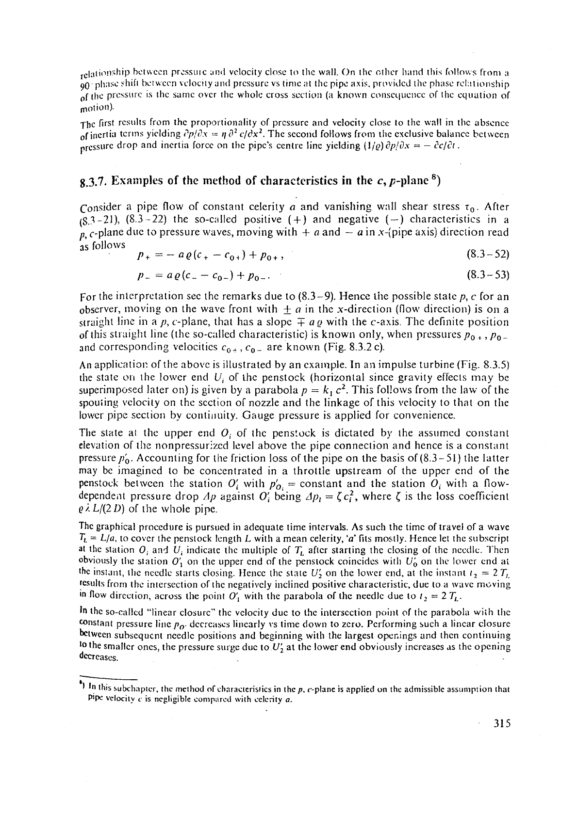
apglicati31: of the above is illustrated by an exa~nple. In an impulse turbine (Fig.
8.3.5)
the statc
011
the lower end
U,
of the penstock (horizontal since gravity effects may
be
superinlposed later on) is
given
by
a
parabola
p
=
k,
c2.
This fol!ows from the law of the
spouiing \~elocity on the section of nozzle and the linkage
of
this \relocity to that on the
lower pipe sectior~ by contil~uity. Gauge pressure is applied for convenience.
The state at the upper end
Oi
of the penstock
is
dictated by the assr~med constant
elevation of
the nonpressurized level above the pipe connection and hence is
a
constant
pressurepb.
Accounting for the friction loss of the pipe on the basis of (8.3-51)
the
latter
may
be
imasined to be concentrated in
a
throttle upstream of the upper end of the
penstock between the station
Of
with
pb,
=
constant and the station
Oi
with a flow-
dependent pressure drop
/lp
against
0:
being
Jp,
=
CC;,
where
[
is the loss coefficient
Q
;.
Ll(2
11)
of the whole pipe.
The
graphical procedure is pursued
in
adequate time intervals. As such the timc of travel of a wave
TL
=
Lla.
to cover the penstock lcngth
L
with a mean celerity,
'a'
fits mostly. Hence let the subscript
at the station
0,
and
U,
indicate thc multiple of
T,
after starting the closing of the ncctilc. l'hcn
obviously the station
0;
on the upper end of the penstock coincidcs with
Ub
on thc lo\tdcr end a:
the instant,
Ihe
needlc starts closing. Hence
the
state
U;
on the lower end, at the inqtnnt
t1
=
2
T,
results
from thc intersection of the ncgativcly inclined positive characteristic, due to a wave m~ving
in
flow
direction, across the point
0;
with the parabola of the needlc due
to
t,
=
2
TL.
In
the SO-called "linear closure" thc velocity Juc to the intersection poi~lt of the parabola
wiih
tl~c
"Ilstant pressure li~le
p,.
dcc:c;rscs lit~crlrly 1,s time down
to
zero. Performing such a linear closure
bctwccn
subsequent
needle positions and beginnins with the largest operings and then continuing
tothe smaller ones, the pressure surge due to
U;
at
the lower
end
obvioitsly increases as the opening
decreases.
-
'1
In
this subchaptcr. the metliod
of
chnracteristics
in
the
p.
<.-plane
is
npplied
on
thc admissible assl~mption that
pip.
velocity
c
is negl~gible conip;~rcd with selcrity
a.
--.s'"u
for the loss
ir?
the pe11sttick, COIlCCntratcd
.
-
In
a
,p~$&&~,,o,,,,;
.
tlo~~lc
0'0
txtwc'~i
"1.
tali*
Of
of constant
%
sure and upper end
0
of the penstock.
Needle
0,
-
4-
ka
a
.
11-
s2
1
villvc at thc lowcr cnd of
penstock
U
rcpresrntd
-
celerity
+
cr,
-
tr
in the x-direction (c-dircctjo;g
pcnstock axis). Closure starts at
1
=
0.
Subscrip
il~dicatc the multiples
of
pulse travel time
T,:
-
L/a
along the penstock, Icngth
L.
Hence the largest pressure surgc on the lowcr end of thc pcnstock results
(provided
i~near closu
tvith the same closing rntc) when thc turbine is closed cotnplctely within
2
T,
=
2
Lln,
the so-call(
reflection time
T,
(see
(5.3-7)).
This gives the highest water
hammf,;
blow, the so-called
Jotikovsl
shock, described
1895
[S.138]
but so~nctimes also ascribed to
Alliryi,
who publishcd this later in
19(
[8.139]
:
dp
=
QUC.
(8.3
-
5
Usually this pressure rise is only attained, when the turbine is shut down from smallcr openin!
When tile shut dortn period !arts longer than the reflection timc,
n
further pressure risc on the turbi
is
suppressed by the negati\e pressurc wave, caused by the reflection of the originally positive
w
on the uppcr open end of the penstock.
Usually the shutoff
rate of n valve or gate before a turbine is lowered in steps (at least in two steq
when approxlmatlng to its closing position.
A
reasonable timing of thc shut down would be
as to cause
a
constant pressure surge from any position of gatc or valve.
W
C
To date the following upper limits of water hammer-induced pressure surge
Ap
in relation to:
pressurc
p,
are accepted to depend on the plant's head:
dplp,
=
0,2
to
2
for
'H
=
100
m
to
5
4
Whcrs the pressure falls short of its critical value by
a
pressure wave, that is reflected
asj
underpressure wave, the penstock.wal1 has to withstand buckling. Such stations on the penstoc
usunll:~ located at the upper end near the surge tank. Also an emergency device for suddcn aer
may prevent
3
water colrlmn sepr;l.ation and its subsequent dangcroils collapse due to reversed'
hammer. Such
a
snifting valvc, operated by thc gate ring in the casc of a rapid shut down, is
U
applied on the head cover of Kaplan turbines.
-
The time step procedure for an impeller pump during valve closure (Fig.
8.3.6):
a_eain the state on the lower end of the penstock
U
follows from the state at the
u
end
0
at an instant earlier by the wave travel time
L/a
(required
to
cover the
pens
length
L
with celerity
a).
Fis.
8.3.5.
Schcmc of co~npu(inp lransicnts
in
I),
c-plane for
closing
tllc nccillr:
v;\lvc
of an
illlpU
sc turbine ttl~rh
(0,).
and without
(0:)
account;,,
by a parabola, whose opening varics with the
stant
t,.
A4
penstock rnitlpoint
o,,
q,
charactc
tics in
a
y,
c.-pli~ne for states
(p,
c)
moving
.
.
.
..