Raabe J. Hydro power - the design, use, and function of hydromechanical, hydraulic, and electrical еquipment
Подождите немного. Документ загружается.

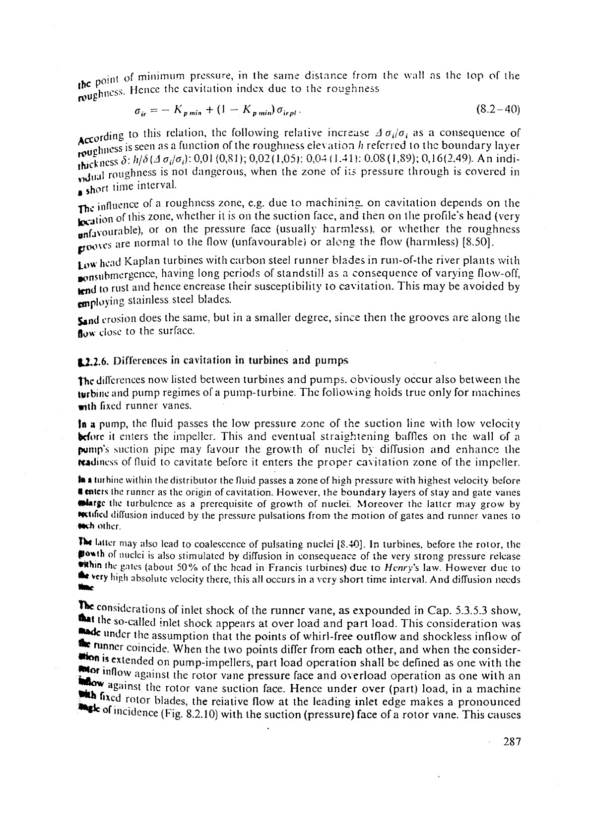
point
of
rni~lilnmtm pres?ure, in the salns disin~ce from the \v;~ll as the top
"f
,lie
hllcss. Hence the cavitation indcx duc to the
roughness
mug
6
11
=
-
min
+
(
1
-
'
p
Inin)
oilp,
.
Asording to this relation, the following relative incrcase
J
oi/oi
as a coliseqoelice of
wuehl,css is see11 as a f~111ction of the ro~~ghlless elel ;ition
h
referred to tlic boundary layer
Ilu;Llless
5:
h/h
(J
a,jo,):
0,01
(0,81); 0,02 (1,Ojj:
0,Oi
(1.41
l:
0.08
(I
,S9):
0,l
G(2.49).
An indi-
4,1,1
rollph~~~~ is not dangerous, when the zone
of
is
pressure through is covered in
..-
,
shi,r[ tinle interval.
ni
innl1ence of
n
rougl~ness zone, e.g. due to machinins on cavitation depends on the
b-Jlion
of
this zone, ivhsther it is on the suction face, and then on the profile's head (very
O,fJrollr:~ble), or on the presslire face (usually hnrmlsss). or \vlietlier the roughness
,\.cs
are normal to tile flo\tl (u~lfavourablei or alcno- the flow (harmless)
i8.501.
O*
-
-
Lar
hsaJ
Kaplan turbines with carboo steel runner blz.iles in run-of-the river plants rqiill
m,,,,lbmergencc, having long pcriods of standstil! as
2
consequelice of varying flo\~-off,
md
10
rust and hzllce encrease their susceptibility to =\-itation. This may be avoided by
mpluyillg st:linless steel blades.
bnJ
erosion does the same: but in a smaller degree, since then the grooves are alon~ the
B~H.
CIUSC
to the surface.
U.2.6.
Differences
in cavitation in turbines
ar,d
pumps
nc
d~n'crcnces now listcd between turbines and pumps. ob\~iously occur also between the
turb~ric and pump regimes of a pump-turbine. The follo\i-ing hoids true only for 111achines
nth
fixcd runner vanes.
la
a
pump, the fluid passes the low pressure zone of
the
suction line with low velocity
Morc
it
enters the
impeller.
This and eventual straightening baffles on thc wall ~f
a
putt~p'b
wction pipe may favour the growth
of
nuclei
b)
dinusion and enhancc the
rcnd~~lc\s of fluid to cavitate before it enters the propsi =\itation zone of the irnpcller.
hh
l~~rhille
within
the
distributor
the
fluid
passes a zone of
high
przssure
with
highest velocity bcforc
I
Ctllrrx
~hc
runncr
as
the
origin of cavitation. However. the bounciary layers of stay and gate vanes
drrgc
tl~c
turbulence
as a prerequisite of growth
of
nuclei. Xioreover thc latter may grow by
~tficd
tiiffusion induced by
the
pressurc pulsations from the motion of gates and runner vanes to
(rclh
othcr.
f)#
lrrlcr may also lead to coalescence of pulsatin_g nuclei
(8.401.
in turbines, before the rotor, the
B~~th
of
nt~clci
is
also stimulated by diffusion in consequsnc
of
the very strong pressure relcase
mrftftln
Ihc
gnrcs
(about
50%
of
the
head
in Francis turbines) due to
Hcnry's
law. However
duc
to
herY
Iligh
absolute velocity there, this all occurs in a \cry shon time interval. And diffusion necds
Irr
considerations of inlet shock of the runner vane,
as
expounded in Cap.
5.3.5.3
show,
*I
the
so-called inlet shock appe;lrs at over load and
part
load. This consideration was
..dc
mdcr the assumption that the points of whirl-free outflow and shockless inflow of
runner
coincide. When the t\vo points differ from each other, and when the consider-
*
is
extended on pump-impellers, part load operation shall be defined as one with the
."'
illflow against the rotor vane pressure face and ox-erload operation as one with an
Lbw
rgilinst thc rotor vane suction face. Hence under over (part) load, in
a
machine
*Ib
bred
rotor blades, the reiative flow at the leading inlet edge makes a pronouriced
'-
or
incidence (Fig. 8.2.10) with the suction (pressure) face of
a
rotor vane. This causes
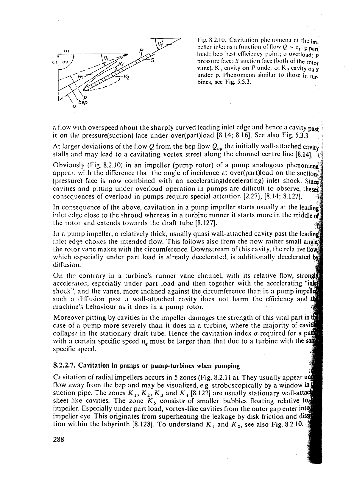
1-ig.
8.2.10.
C':~vi[ation pltcn0nlCtl:l
at
the
im-
pcllcr ink1
;IS
;I
I'i~nslin~l
of
flow
-
C,
.
p
Parti
loacl;
I)cp
13~41
cfficic~lsy pl)il!t;
0
overload;
p
~~CSSIITZ
filcc:
.S
s~~clion t'acc
(both
of
the rotor
v;lnc), K, c:~vity on
P
unclcr
o;
K,
cavity
on
s
under
p.
I'hcno~ncll;~ similar to thosc
in
tuc-
bincs,
scc
ICig.
5.5.3.
bep.
0
2
floV.v with overspeed about the sharply curved leading inlct edge and hence
a
cavity past
it
on
(lie
pressure(suction) face under over(part)load
I5.14;
8.161. See also Fig.
5.3.3.
At larger deviations of the flow
Q
from the bep flow
Q,,,
the initially wall-attached cavity
stalls and may lead to
n
cavitating vortex street along the channel centre line
[8.14].
j:i
Obviausly (Fig. 8.2.10) in an impeller (pump rotor) of a piimp analogous phenorneni
appear. with the difference that the angle of incidencc at over(part)load on the suction.!
(pressurc) face is now combined with an
accelerating(decelerating)
inlet shock.
sin&
cavities and pitting under overload operation in pumps are difficult to observe, the&
conseqiiences of overload in pumps require special atten tion
[2.27],
[8.14;
8.1271.
:F
In consequznce of the above, cavitation in a pump impeller starts usually at the leadin'
i~ilel edge close to the shroud whereas in a turbine r~~nner
it
starts more in the middle
111e rolor and extends towards thc draft tube
[8.127].
In
2
?:imp impeller, a relatively thick, usually quasi wall-attached cavity past the leadin
inlct
cd~e
chokes the intended flow. This foilows also froni the now rather small an
the
ro:or vane makes with the circumference. Downstream of this cavity, the relative
fl
which especially under part load is already decelerated, is additionally decelerated
diffusion.
On
!hc
contrary
in
a turbine's runner vane channel, with its relative flow, stron
acceleratecl, especia!ly under part load and then together with the sccelcrating
"i
s~Gc~'',
md
tlie vanes. more inclined against the circumference thsr? in a pump impe
such
a
diffusion past
a
wall-attached cavity does not harm the efficiency and
machine's
behaviour as it does in a pump rotor.
Moreovcr pitting
by
cavities in the impeller damages the strength of this vital part in
case of a pump more severely than it does in
a
turbine, where the majority of cavi
collaysr in the stationary draft tube. I-Ience the cavitation index
a
required for a
p
with
a
certain specific speed
n,
must be larger than that due to a turbine with the
s
specific speed.
5.2.2.7.
Cavitation
in
pumps
or
pump-turbines
when
pumping
Cavitation
cf'
radial impellers occurs in
5
zones (Fig. 8.2.1 1 a). They usually appear
u
flow away from the bzp and niay be visualized, e.g. stroboscopically by a wiridow
suction pipe. The zones
K,,
K-,,
K,
and
K,
[8.122] are usually stationary wall-att
sheet-like cavities. The zone
K,
consists of smaller bubbles floating relative
t
impeller. Especially under part load, vortex-like cavities from the outer gap enter in
impeller eye. This originates from superheating the leakage by disk
fric!ion and di
tion witl~in the labyrinth
[S.
1281.
To
understand
K,
and
K,,
see also Fig.
5.2.10.
288
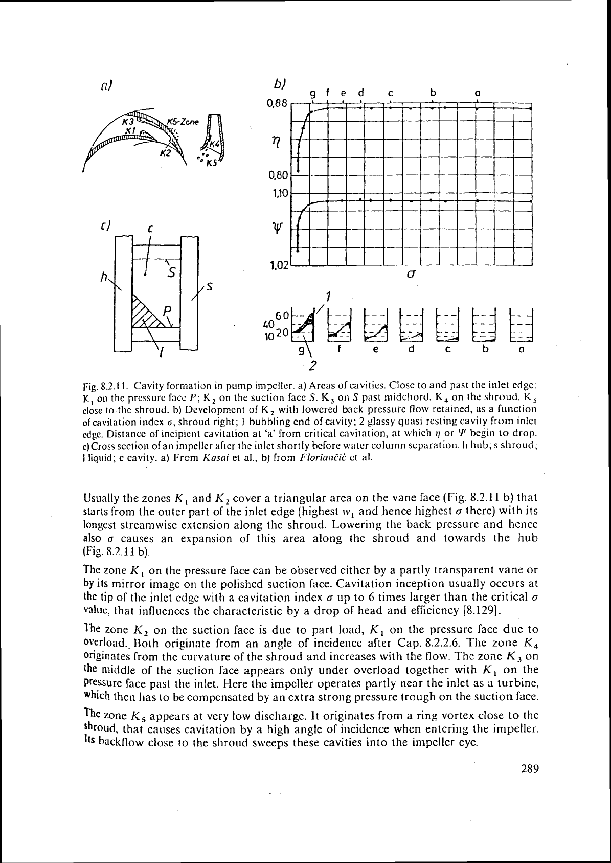
b)
afed
c
b
a
Fig.
8.2.1
1.
Cavity forination in pump impcller.
a)
Arcas of cavities. Close to and past the inlet cdge:
I(.,
o!l the pressure face
P;
K,
on the suction face
S.
K,
on
S
past midchord.
K,
on the shroud.
K,
close to the shroud.
b)
Dcvclopment of
K,
with lowered back pressure flow retarned, as
a
function
ofcavitation index
a,
shroud right;
1
bubbling end of cavity;
2
glassy quasi resting cavity from inlet
cdge. Distance of
incipient cavitation
at
'a'
from critical c:ivitation, at \vhich
11
or
Y
begin
to
drop.
c)Cross section of
an
in~pellcr after the inlet shortly before
water
column separation. h
hub;
s
shroud;
I
liquid; c cavity.
a)
From
Kusai
et al.,
b)
from Flor-iunc'iC et al.
Usually the zones
K,
and
K,
cover a triangular area on the vane face (Fig. 8.2.1
1
b) that
starts from the outer part of the
inlct edge (highest
w,
and hence highest
a
there) with its
longest streamwise extension along
the shroud. Lowering the back pressure and hence
also
a
causes an expansion of this area along the shroud and towards the hub
(Fig. 8.2.1
1
b).
The zone
K,
on the pressure face can be observed either by a partly transparent vane or
by
its mirror image on the polished suction face. Cavitation inception usually occurs at
the
tip of the inlet edge with a cavitation index
a
up
to
6
times larger than the critical
cr
value, that influences the characteristic by
a
drop of head and efficiency
[8.129].
l'he
zone
I<,
on the suction face is due to part load,
K,
on the pressure face due to
overload.. Both originate from an angle of incidence after Cap. 8.2.2.6.
The
zone
K,
originates from the curvature of the shroud and increases with the flow. The zone
K,
on
the
middle of the suction face appears only under overload together with
K,
on
the
Pressure face past the inlet. Here the impeller operates partly near the inlet as a turbine,
which the,: has to be compensated by an extra strong pressure trough on the suction
face.
The
zone
K,
appears at very
low
discharge. It originates from a ring vortex close to the
that causes
cavitation by
a
high angle of incidence when entering the impeller.
Its bilckflow close to the shroud sweeps these cavities into the impeller eye.
\L'itli \,i~ck j,rc?;sure dccrc:~scd. the c;!vi~ics
ii
,
,
k'.,
(,I-
K,.
K.,
co;~lc.scc.
Ic.;i\.i~~s
fi~i~ll~
;,
s111;tlI ti.i;~~i:~~!;ir cross
SCCI~OII
for thc 110~
(l:-is.
S.2.
I
I
C)
I.)ci;)~-c IIlc I;ittcr is cut
off
b.
Y
ca\.il;ition.
AI
any ralc, pirlil~g oci.~~~.s only
1311
tlic
~C;II.
of
111~
\\.;I~~-;III;Ic~c~~ C;l\,ilicS
look
illg soniclion "foamy" in co~itr:lst to
t
he ~in>rc "gl:~siy" :~p~>c:~ra~iw
of
tlie cavity
pilr;
;111c;td.
Diagonal and axial i~npcllcr ~11111~s Ii;~ve only. tlic t1li.e~ ;Irci\S
li,.
K,. K,
fro~n
the
a1.01-clncr~tioned cavitation mncs
(Fig.
8.2.
I
1
a).
blorcovcr
IIICW
i1iipc1Ic1.s
II;\\~c
3;1p c;\~i,
tat ion in tllc tip cltarancc anil in thc
C:IS~
of
;id~ii1~1,101~
\;III~S
:~Isc)
111
lllc lil~b cI~;I~;~~~~~.
Then. to avoid fatigue cffccts at thc tr;lnsition bct\vccn bli~dc and pivot. Ihc
innermost
vanc profile must be thickcncd at tiic groove bcl\vccr~ bli~dc and disk
()I'
the pivot. This
crruscs fillet cavitation thcrc
(Fig.
8.2.1
1
a)
[8.126].
F1uctu:iting cavities, whicli rnay occur away frorn thc bep. may ten~poraril} choke
the
llo\v. This causes water hammer, which in return inll~~c~lces thc c:ivitics [Q.I
I].
9;
*f
3.2.2.8.
Cavitation
in
turbines
P
In a turbine the cavitatin? zones are similarly located as corrcspo~lding in pumps. Also
here the ~va 11-attachcd cavity past the leading inlet edgo of the ru~?ner vane in
u
rotor with
fixed vanes due to palt load appears on the suction hcc ancl the ccrl.csponding cavity
due
to overload on the pressure face. That means in the pnrtload regimc the additiona]
pressure trou~li due to an angle of incidence supp:)rt\ the intended
flon
and hence
improves [lie efficiency. Ho\i.ever, in tlic over load rcgimc of
a
turbine t!i!> pressure trough
on
tile pressure face countcracts the pressure clist ri t)ulion of
a
~urb~nc runner intended
and hence worsens the efficiency.
i
'
In
addition turbines with fixed runner vanes have also wall-;ittncticd ci~vities past th
leitdin~ inlet edge of runner under varying head-(Fig.
5.3.3).
Wllen :hc Iiend falls short
its
rated
value such a cavity appears on the pressure frlcc. This may occur- \vhen
a
turbi
is
supplied by a reservoir during its filling: If thereby tlic anglc of
incidence
exceeds
certain value, the flow stalls
at
the lendin: cdgc. then shcd<ling
:I
c;t\.it:~ting vortex she
along the interior of the channel, causing noise and \,ibrntions
[5.130].
The problems
due
to wall-attached or stalling cavities
as
a consequence
of
flow
and
hcad variatio
are
:omc\vhat
facilitated.
but
not co~npletely elirninatcd
by
means
of
uc(i~~st;~blc
runficr
vanes;
desxibcd
by
Eic.lilei
and
Joegt-r
[S.
161.
In
these m;tchines. at retained hcad, the inlet shock
at
ovcr
(part)
load
results
in
a
cavity
o
suction (prcssure) face of the runner blade. The contrary
11:ippcns
in
niacliines
with
fixcd
ru
blndcs. Usu:~lly
in
run-of-river plants, according
tu
the
flow and head Jur:ttion line,
KTs
adjustable
runner
blades operate undcr
pilrt
toad
with
a
he;ltt largcr and
undcr
overload
with
a
smaller than the rated one. Thus the overload cavity
usurtlly
shifts :gain towards thc pressure
and
the part load cavity towards the suction face.
(Load
is used hcie in the scnsc of discharg
cspounded
in
Cap.
5.3.5.3.)
In reaction turbines with fixed runner vanes the precessing cork scrcw vortex pas
rgnner usually cavitates
in
its core (Fig.
8.2:lZa)
(detrlils Cap.
5.5).
Also the core
0
strr~ight vortex in the draft tube due to overload cavitates. See Fig.
8.2.12
b.
By
the radial pressure _gradient, air diffuses also into thc vor!ex core.
This
make
vortev core elastic
and
capable of oscillnti~ig in connection with the surrounding
m
\Ira
tzr.
Such oscillations may be excited
by
water hammer-indaced pressure surges
systeni penstock turbine draft tube tailrace gallery, stimulated by changes in gate
po
due to varying load demand, but also excited
by
thc precessiilg excentric vclocity
fie
to
the cork screw vortex
[5.51
to
5.55!, [8.95], [9.45
to
9-51].
290
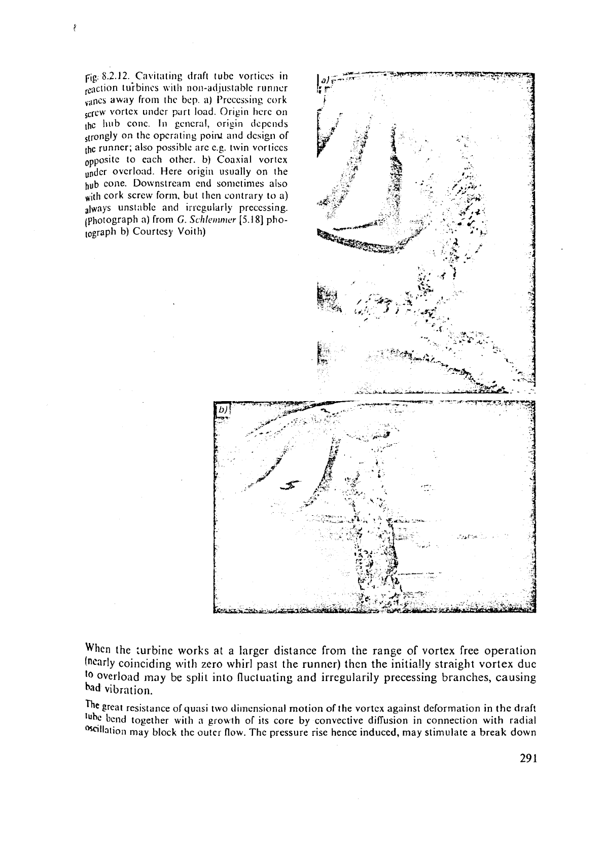
rig
8.2.12.
Cav~tat~ng draft tube vortices in
-
~--G-~~c~
a)
t-
-*
7'
lcact~~n tuibincs with non-adjustable runncr
I*
,
,i,ncs away from the
bcp.
a)
Prcccs~ing cork
1
Screw
vortex
undcr part load. Or~gln hcrc
011
,hc
Iiub cone.
In
gcncral, origin dcpcnds
on the opcr:~ting poilu
and
design of
runner; also possible arc
c.g. twin vortices
to each other. b) Coaxial
vortex
overlo~td. Here orig111 usually on the
.."
hub
cone. Downstrean1 end sometimes also
,ith cork screw for~n. but thcn contrary
to
a)
unst;\blc and irregularly prcccssing.
(photograph
a)
from
G.
Scl~lcrrlrllcr
[5.18]
pho-
lograph b) Courtesy Voith)
t
/
*-
*
-%
,
wa-
-
-,
.
.
,
,
.*:3
+c-
*r
-%lr.&-;.lrcWu..--
'
When
the turbine works
at
a
larger distance from the range of vortex free operation
coinciding
with
zero whirl past the runner) then the initia!ly straight vortex
due
10
overload
)nay
be
split into fluctuating and irregularily precessing
branches,
causing
had
vibration.
The
great resistance of qu:lsi two clilnensionnl motion of the vortex against deformation in the
draft
'~hc
bend together with a growth of its core
by
convective diffusion in connection with radial
Oscillation may block the outer flow. The pressure rise hence induced, may stimulate a break down
4
I,
18
:
?
of
thc vortc-, by s\vecping
it
tiownstream. S~ich accidc.ntnI cff~cts lnny
hc
;iccomp;lnied
by
h:lnrmcring
5
load cll,~~igcs oil tlic hcnrl covcr ;~nd thc hliaft
[Q.
13
1
;
8.1331.
l'ljis ozc~lrs
i~t
ovc~.l~,~tl. t\ftcr
~rnrlsr
an occ;~$lon;tl break down
t;f
the vortcx might also originate f~um the nccclcr;rt~on of niain
flow
in
thc diffuscr bcnd.
.
Turbines of highcr specilic speed
especially
KTs cavit~lte sevcrely uuder runaway.
~~;,ii
'
[8.17]
has hinted at a non pitcl~ pcriodic;\l cavity formatioo of KTs under rilllaway, lillked,
j
to
an
extra
high
runaway speed.
$4
B
A
spcci;ll coviiation-like erosion occasionally is obscrved on the back side of tllc buckel
I
of impi~lse turbines (I'Ts) near the jet cut out
[8.18].
This can be attribtited to the
impact
of droplets. that are overtaken by the bucket.
Some
of
the cavitaiional phcnomena originating from
then also
the losscs duc to
it)
could be clirninatcd by
could be done
~norc casily in planis using
DC
high voltage powcr transmission.
011
the othcr hand
this would bring
in
a lot of rather
expensive
problcms on thc side of stnblc rcgulation and electric
powcr tr:insmission. That is to say it would shift the problctns from the turbine sictc to thc electrid
side.
Co:ltrar;r to small pumps wiih permissible head drop of up to
3%
due to cavitation, for the loss
of
re\renue,
an
efficiency drop due to cavitation is not admitted in turbit~cs. For
Kllapp's
erosion
la&
(8.2-221
in high head turbo machincs the slightest cavitation erosion should
be
avoided.
I'hcrcfoie the suction head and the cavitation
i
beforehar~d with respect to the corresponding critical c
to erosion). This is done on thc basis of model tcsts, preferably on onc and the same stand
cficiency and cavitation tests
[8.10].
The
hydrodynamic effects of cavitation are usually stroboscopically observed tl~rough
mindov:
in
the draft tube of a model.
As
rti?
example co~sider
a
Kap!an t~!rbine, (Fig.
ate.; without
any
effect on
q,
H
or
Q.
At low
cavitation
at
the
hub
groove occurs (Fig.
8.2.13
the relatively snlall relative velocity there, this
in
a
leaas
to
tip clearance cavitation (Fig.
8.2.1
velocity there and
Ktlnpp's
erosion
law
(5.2-2
a;
30,
O
j.1
I
!
li
ii
!
i.!q;-
I-
ssi
,
,.
,
i,7&&
i!
.
,
c"3i-
;
I
/
a
I
!i:j
i
75-
,I
:
r-jq,j--
I!
I
t'
I:
I
.I
I!
eL
il
:
--
PS
19
78
17
16
Q?
7.0
d-
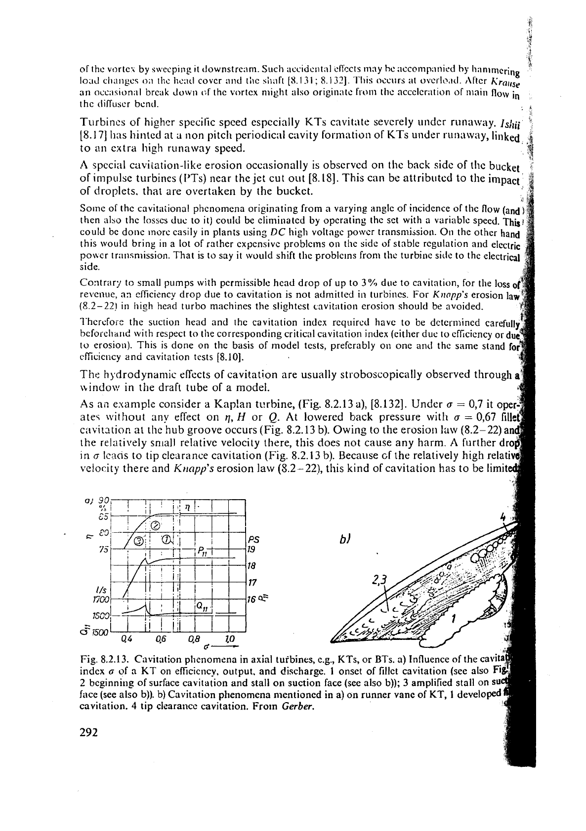
Fig.
8.2.13.
Cavitation phenomena in axial tuibin
indcx
G
of
n
KT
on eficiency, output, and discha
2
beginning
of surface cavitation and stall on sucti
face (see also b)).
b)
Cavitation phenomena nlentio
cavitation.
4
tip cleara~lcc cavitation. Frorn
Gerber.
292
ÿ his
is (lone either
by
cavitation fins (Fig. 10.2.25) or by ~nntcrial, rcsistnnl to cavitation
erosio~i
"11
least in the form of building up welding or that of linir~g
on
the vane :ind the
ring.
usually the suction head is defined up to the runner exit. However in a large
KT(D
up
to
11,3
ni) the critical point due to tip clearance cavitation on the prototype mny
be
aboui
3
m
above the runner vane's rearward edge. Therefore the prediction of
It,
for this case
by
means of (8.2-27) has to be based not on tlie small model
(D
=
0,3
to
0,6
111)
but on
the elevation the real critical point of the prototype has above tailivr~ter.
\vhen
a
of tlie turbine considered falls short of 0,5,
flow
separation starts due to cavitation
on
the suction face of runner vane. Hence
a
drop in output and efficiency appears. This
pint
has
to be avoided
ill
the prototype wit11 d11e consideration to cavitation scale effects.
For
the latter the head might be
H
=
30
m
and
the
safety margin at this point \\.ith respect
to
scale effects
Aa
=
0,04. Then
Ah,
=
0,04
.
30
=
1,2
n~ must be subtrrictzd from the
11,
obtained from the measured
rr
of this critical point by formula (8.2-27).
Only for informatiol~ but without consequence to application
it
may be stared
(Fig.
8.2.13)
that, when
a
011
the machine is lowered belo\s
0,5,
the
efficiency
continues
decreasing but flow and output show a slight peak, probably
from a lowered draz.
A
further drop of
o
chokcs and finally blocks the flow.
In
the
follo\iling
some
practical hints
may
be
given
after
Jueger-
and
Eichlcr-
(8.161
concerning
observations
on cavitating niackincs and kecping cavitation undcr control. The foilol\ing
itc'nis
should
be observcd
in
model and prototype
if
possible:
a)
Extent of cavitation
in
area
(cavity
or
pitting)
b)
Characteristic cavitation pattern (clo~~dy, compact,
vertical)
C)
Efl'ect
of c;~vitation on pcrformailce.
Plant
should be reviewed over a
certnin
working period.
The
following
items
should
be
noted during
operation,
lo
obtain
thc
linkage
betweell flow ficld and
pitting
rate
at
a
certain
prototype:
d)
Flow range
e)
head
range
f)
altitude
range of tail water,
g)
hours of operation due to conditions
d)
through
f),
the
items
d)
and e) should be ~cfericd
to
rated
figures.
At
a
runner inspcction, location,
extent
and depth of
pitting
or pitting arca should bc r.otcd.
8.2.2.9.
Protective
meos~~rcs
against
cavitation
1)
Correct fixing of suction head: (Fig. 8.2.6 a)
11,
follows from (8.2-27). To limit a certain
undesirable cavitation,
h,
as
the elevation of this special critical zone above the tail-water
in
the prototype must be accounted for. Fixing of
a
with sufficient distance from a,,,
defined
by
1EC
code. When
a,,
is from
a
tnodel test, then adding to this
AG,,
due to scale
eNcct.
hticr may be divided into predictable physical scale cflects (due to
length
scale, due to
Reytlolds
number ctc.)
and
accidcnt:ll
scale
cffccts, e.g. due to non retained geomelry
of
the
prototypc
with
respect to
the
draft
in
consccl~~c~~ce
of
errors of foundary, of machining, failures due to transport
(roughncsses duc to cranc cable, road accidents), f:~ilurrs during asscmbly on
site,
c.g.
by
wrong
adapted
civil
engineering work
e.g.,
from
the
lining
of
the
throat
ring
to
the
concreted draft tube
wall.
Fixing
11,
requires coniplcle knowledge of the hydrograph, back water effect, working
Programme of the
pii~nt, the altitudc of the site and its lowest possible barometric
Pressure,
the highcst possible water temperature and corresponding vapour pressure. It
m~st be mentioned that setting
h,
must
bc
done also with a side glance on the excavation
COSI
~~npIi~:d. IJI~I.,~II,II 0p~ri1ti011. c.g. wi:h
il
stro!ig i~nglc o( inciiicncc during
fillillg
I~LI~C
rcsr:r\
01
I
!:,LI,I'o~
1)c
l;~
kc11 in1
o
i1cc0111it.
1'11~
~ii1r~ilio11 of sllch "ccccntric operatio
niuht
5c
IIO~ICCJ.
111
generill
I
lic
n
L
i1111c due to illc prcssurc trough cililse(l by an allfie of incidence
tt
leildillp inlei cdgc of the rilnncr woilld result in an u~leconomic;lllp
ducp
~~bmer~~~~~~
LIIC
set.
:$I
Such an
operation
should be nvoirled or limited
in
time. Its consequences should
includcd into
i:
revision
ant1
repair program.
The
opcrator of
n
plnllt must he conscinl;
that thc molncntnry Iucrativc operation bclow the
--T
economy and ,~vailabiiity of
a
plant. In general a turbine could escape such operatin
cbnditions by adequate pvsitiorl of gates.
9
$
In pump-turbinzs during pumping this flexibility is lost by the then necessary block$;
of
gates
in
t!lr
optimum position, situation which also exists in storage pumps. To
pitting
I"
high
head
pump-tarbines, K~I(I/~I's erosioli law may require subnlergences
$
adhering
a!,
strictly
as
possible to
the
direction that
a,,,
(available due to the moment
head and
t:lil
ivater levcl)
rs
always above the
a,,
(req~ired for opcrating the machin
accordin; to its characteristics and with respect
to
pelistock loss).
,.I
1
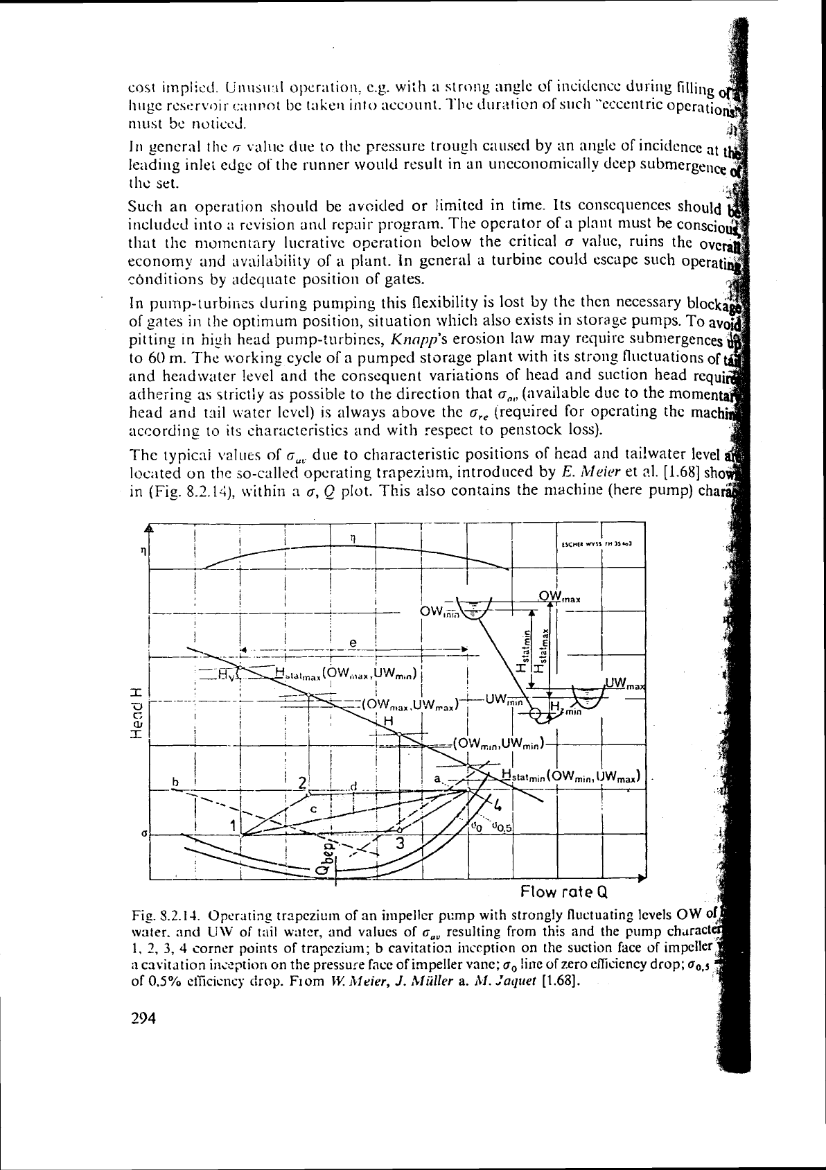
The typicni
values
of
G,~
due to characteristic positions of head
and
tai!water level
4
1uc;lted
on
the so-called opcrating trapeziam, introduced by
E.
iV1eit.r
et
31.
[1.68]
shop;
in (Fig.
8.2.1-1),
~vithin
a
G,
Q
plot. This also contains the niachine (here pump) chal
t
I
I
I
:
In--
rIIsa
1,
2,
3,
4
corner
points of trapczitlm;
b
cavitatioa incrption
on
the suction face of impeller
;i
caviration incqtion
on
the pressure face of impeller vanc;
o,
!ine
of
zero
efIiciency
drop;
oo,s
of
0.5%
eificlcncy
ctrop. F~om
I.V.
111
eier,
J.
Miiller
a.
111.
laquef
[1.68].
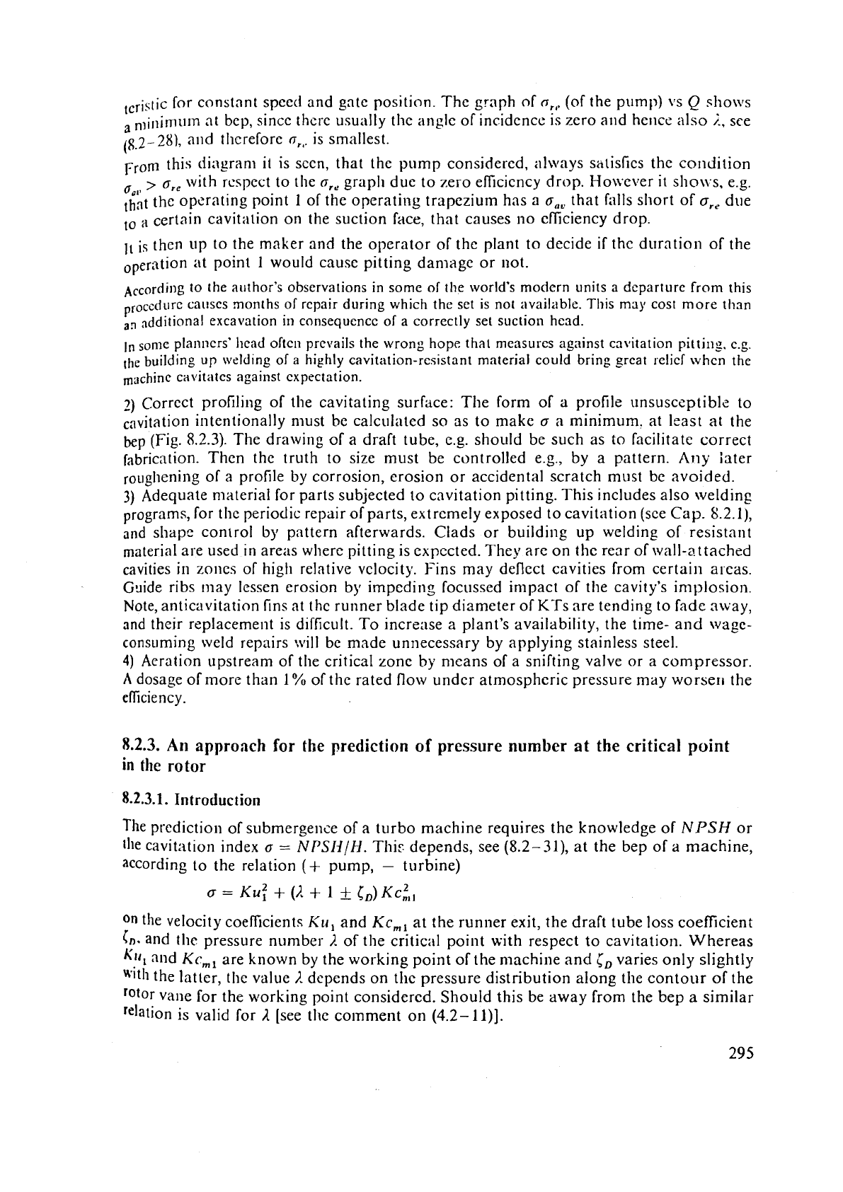
I,rjstic for constant speect and gate position. The graph of
or,
(of the pump) vs
Q
sho\~s
a
nlinimum at bep, since there usually the angle of incidence is zero and hence also
i,
see
(p,2-28),
and tllcreforc
or,.
is smallest.
From this dingram
it
is sccn, that the pump considered, always
satisfies
the co~iciition
00,l
>
or,
with rcspcct to the
cr,,
graph due to zero eficicncy drop. Hoivever
it
slio~~s, e.g.
that
the operating point
1
of the operating trapezium has
a
o,,
that fillls short of
a,,
due
to
a
certain cavitation on the suction face, that causes no eficiency drop.
11
is then up to the maker and the operator of the plant to decide
if
the duration
of
the
at point
1
would causc pitting damage or not.
~~cordillg to the author's observations in some of the world's modern units a departure
from
this
proccd~~r~ causes months of repair during which
the
set is not ;~vail;ible. This
may
cost
more
than
,,
additional excavation in consequence of a correctly set suction head.
In
sonle planners' head often prevails the wrong hope that measurcs against cavitation pitting, c.g
the
building up welding of a highly cavitation-resistant material could bring great relicf when the
cavitatcs against expectation.
7)
Corrcct profiling of the cavitating surfice: The form of
a
profile unsusceptib1,- to
"
rnvitation intentionally must be calculated so as to make
a
a
minimum. at least at the
bep (Fig. 8.2.3). The drawing
of
a draft tube, e.g. should be such as to facilitate correct
fabrication. Then the truth to size must be controlled e.g., by a pattern. Any iater
of a profile by corrosion, erosion or accidental scratch rnust be avoided.
3)
Adequate material for parts subjected to cavitation pitting. This includes also welding
programs, for
the periodic repair
of
parts, extremely exposed to cavitation (sce Cap. 8.2.11,
and shape control
by
pattern afterwards. Clads or building up welding of resistant
material are used in areas where pitting is expected. They are on the
rear of wall-attached
cavities
in
zones of high relative velocity. Fins may deflect cavities from certain aleas.
Goide ribs may lessen erosion by impeding focussed impact of the cavity's implosion.
Note,
anticavitation fins at
thc
runner blade tip diameter of KTs are tending to fade away,
and their replacement is difficult. To increase
2
plant's availability, the time- and wage-
consuming weld repairs
:vill
be made unnecessary by applying stainless steel.
4)
Aeration upstream of the critical zone by means of a snifting valve or a compressor.
A
dosage of more than 1
%
of the rated flow under atmospheric pressure may worseri the
efliciency.
8.2.3.
An approach
for
the prediction
of
pressure number
at
the critical point
in
the
rotor
8.2.3.1.
Introduction
The
prediction of submergence of a turbo machine requires the knowledge of
NPSH
or
the
cavitation index
a
=
NPSNIIl.
This depends, see (8.2-31), at the bep of
a
machine,
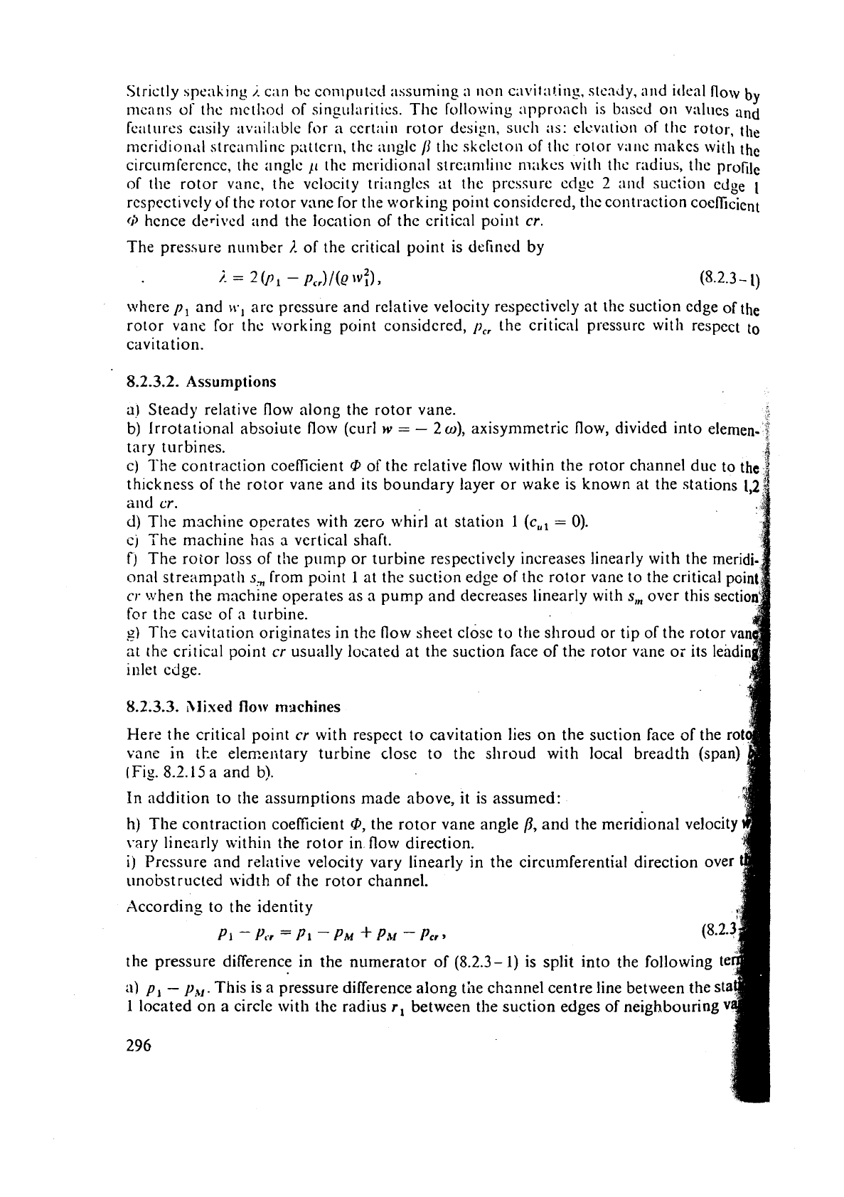
according to the relation
(+
pump,
-
turbine)
On
the velocity coeficients
h'u,
and
Kc,,
at the runner exit, the draft tube loss coefficient
in.
and the pressure number
i,
of the criticit1 point with respect to cavitation. Whereas
Kill
and
Kc,,
are known by the working point of the machine and
j,
varies only slightly
wit11
the latter, t11e value
i.
depends on the pressure distribution along the contour
of
the
vane for the
working point considered. Should this be away from the bep
a
similar
'elation
is
valid for
R
[see the comment
on
(4.2-
1
I)].
Strictly 5pe:lling
/.
can he complltsd :~ssuming
:I
lion cavit;~linp, stenJy, and ideal flow
by
nicans
ol'
the nictl;od of singulnritics. Thc following approach
is
based on vr~lt~cs and
features ertslly availi~ble for
a
cert;iin rotor design, such :IS: clcviltion of thc rotor, the
mcridion,il strcamlinc p;\ttcrn, thc nllglc
/I
tllc skeleton of thc rotor v:lllc nlakcs with
the
circu mfcrcncc, the angle
jl
the mcridional strei~nllinc niakcs with the radius, the profile
of the rotor vnnc, the
velocity
tri:~ngles at the prcssure cdgc
2
a11d suc:ion
edge
1
rcspectivcly of thc rotor vane for the working point consitlercd, the contraction coefficient
0
hcnce tierived and the location of the critical point
cr.
The pressure number
1.
of the critical point is defined by
\vhcre
p,
and
W,
are pressure and relative velocity respectively at thc suction edge of the
rotor vane for the ivorking point considered,
p,,
the critical pressure with respect
to
cavitation.
8.2.3.2.
Assumptions
a)
Steady relative flow along the rotor vane.
b)
Irrotational absoiute flow (curl
w
=
-
2
w),
axisymmetric flow, divided into elemen-
tary turbines.
4
C)
The
contraction coefficient
@
of the relative flow within the rotor channel due to the
fi
thickness of the rotor vane and its boundary layer or wake is known at the stations
1,2
and
cr.
d)
The machine operates with zewhirl at station
1-(cF8).
cj
The machine has a vertical shaft.
f)
The rotor loss
of
the pump or turbine respectively increases linearly with the meridi-
onal streampath
s,
from point
1
at the suction edge of the rotor vane to the critical point
cr
when the machine operates as a pump and decreases linearly with
s,
over this sectio
fclr the case of a turbine.
U)
The
cavitation originates in the flow sheet closc to the shroud or tip of the rotor
va
.-
at
the critical point
cr
usually located at the suction face of the rotor vane or its leadi
inlet ciige.
8.2.3.3.
hlixed
flow
machines
Here the critical point
cr
with respect to cavitation lies on the suction face of the rot
vanc
in
the
elemelitary turbine close to the shroud with local breadth (span)
(Fig.
8.2.15
a and b).
In
addition to the assumptions made above, it is assumed:
h)
The
contraction coefficient
sP,
the rotor vane angle
13,
and the meridional velocity
\-ary linearly within the rotor in flow direction.
i)
Pressure and relative velocity vary linearly in the circumferential direction over
unobstructed
width of the rotor channel.
According to the identity
PI
-
Vcr
=
PI
-
PY
+
PY
-
Pcr,
the pressure difference in the numerator of (8.2.3-
1)
is split into the following t
a)
p,
-
p,,,.
This is a pressure difference along the chznnel centre line between the st
1
located on a circle with the radius
r,
between the suction edges of neighbowing
296
