Raabe J. Hydro power - the design, use, and function of hydromechanical, hydraulic, and electrical еquipment
Подождите немного. Документ загружается.

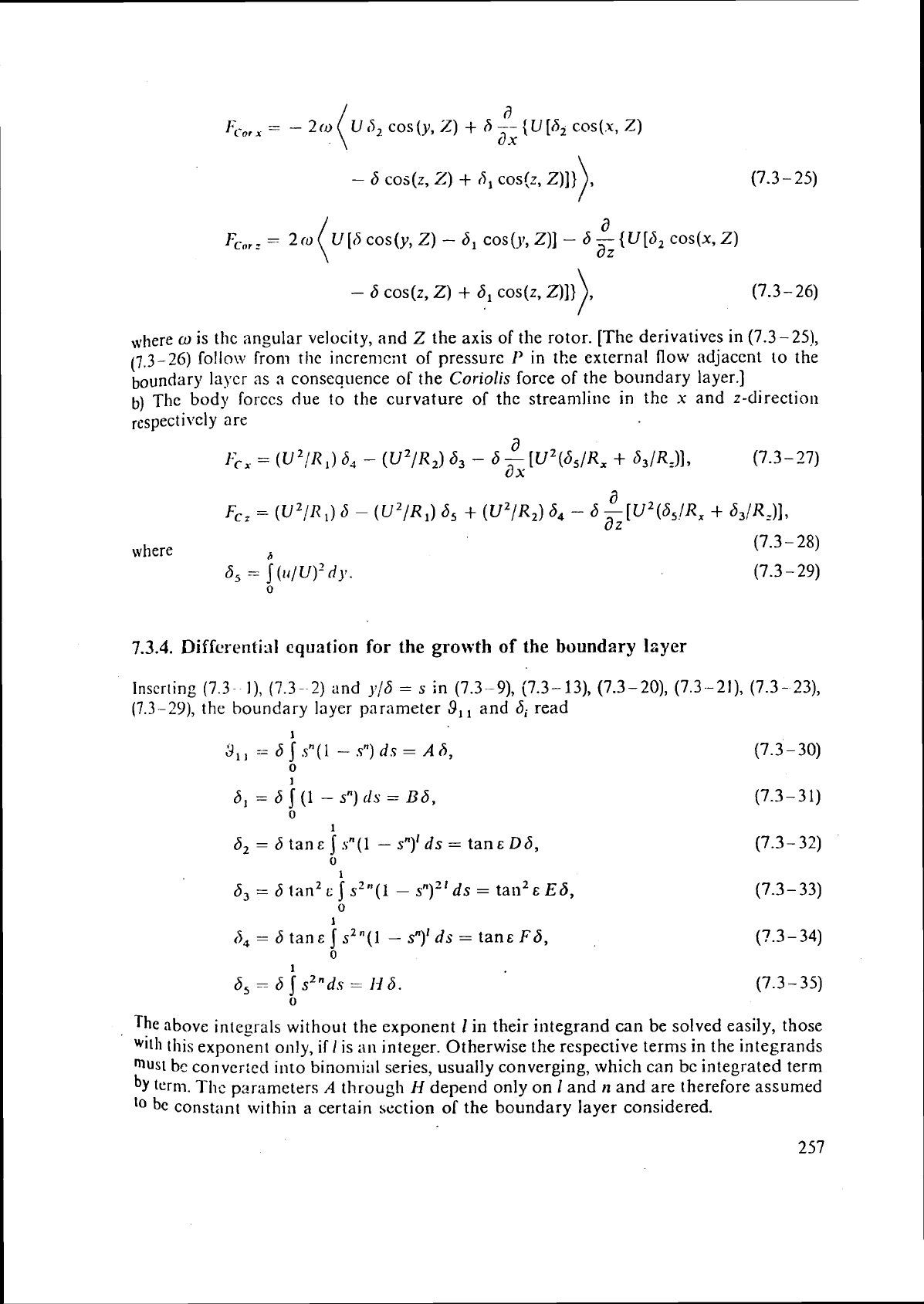
a
U
[d
cos
(y,
Z)
-
b1 cos
()I,
Z)]
-
b
-
{
U
[b2 COS(X,
Z)
az
-
6 COS(Z,
Z)
+
6, cos(z, Z)])
(7.3
-
26)
,+!here
w
is thc angular velocity, and Z the axis of the rotor. [The derivatives in (7.3-251,
(7.3-26) follow iron1 tlle incremcilt of pressure
I'
in the external flow adjacent to the
boundarg laycr
3s
a
consequence of the
Coriolis
force of the boundary layer.]
b)
The
body Corccs due to the curvature of the
streamline
in the
x
and z-direction
respe~ti\.~ly are
d
FcZ
=
(U2/R 1)
6
-
(U2/R1) 6,
+
(u2/R,)
64
-
6
-
az
[U2 (b5!Rx
+
d3/Rz)],
where
A
(7.3
-
28)
6,
.=
5
(u/
U)'
dy.
0
7.3.4.
Differential
equation
for
the growth
of
the boundary layer
Inserting
(7.3
I),
(7.3
--I)
and y/6
=
s
in (7.3-9), (7.3- 13), (7.3-20), (7.3--2l), (7.3- 23),
(7.3-29),
the boundary layer parameter
9,,
and bi read
1
6,
=
6 j(l
-
sn)ds
=
Bb,
0
1
b2
=
6 tan&Ssn(1
-
sn)'ds
=
tan&Db,
0
1
b3
=
6 tan2
c
5
s2"(l
-
s")~' ds
=
tan2
E
Eb,
0
The
above integrals without the exponent
1
in their integrand can be solved easily, those
,
.
Wl1h
this
expo~lerlt only, if
I
is
an
integer. Otherwise the respective terms in the integrands
must bc conver:cd into binomial series, usually converging, which
can
bc
integrated term
term.
Thc
pawmeters
A
through
H
depend only on
1
and
n
and are therefore assumed
lo
bc
constant witllin a certain section of the boundary layer considered.
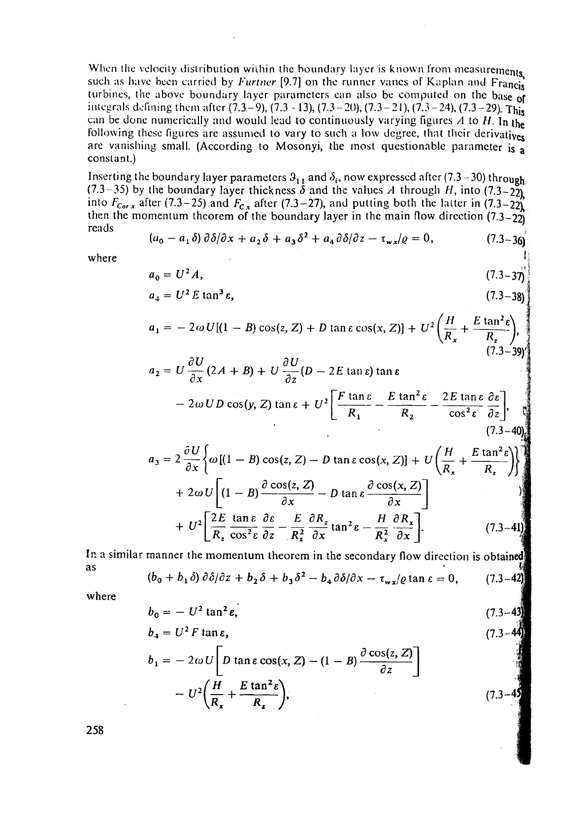
When
the vclocity ciistribution wiihin the houndary Iaycr is known from 171easurement
s,
such
;IS
hitvc hccn carriccl by I'urttrer [9.7] on thc runncr vanes
of
Kaplan ancl Francis
turbines, tile ;~bovc buirndary layer p:irameters can also be computcd on the base
of
i~itcgrals d,:Iining than :iftcr (7.3
-
9),
(7.3
-
13), (7.3
-
70),
(7.3
-
2
I),
(7.3
-
24)-
(7.3-29).
This
can
be done nun~eric:~lly
and
would lead to continuously varying figures
A
to
fI.
In
the
following thesc figurcs are assun>cci to vary to such
a
low
degree,
that
their derivatives
are vanishing small. (According to Mosonyi, the most questionable parameter
is
a
constant.)
Inserting
thc boundary layer parameters
3,,
and
6,.
now expressed after (7.3-
30)
through
(7.3-
35)
by the boundary layer thickness 6 and the values
A
througl~
H,
into (7.3-22)
into
F,,,,
after (7.3-25) and
F,,
after (7.3-27), and putting both the latter in (7.3-22i
then the momentum theorem of the boundary layer
in
the main flow direction (7.3-22)
reads
(a0
-
a,
6)
a6/dx
+
a26
+
a3S2
+
a,dd/dz
-
z,,/@
=
0,
(7.3-36)
where
a,
=
U2 A,
a,
=
U2
E
tan3
E,
Ir,
a
similar
as
where
a,
=
-
2/oU[(l
-
B) cos(z,
2)
+
D
tan& cos(x,
Z)]
+
U2
au
au
a,= U-(2A+B)+ U---(D-2Eta11~)tall.s
ax
a
z
Ftan&
E
tan2& 2Etan~
a&
-
2co
UD cos(y, Z) tan
E
+
U2
R2
o
[(I
-
B)
cos(z, Z)
-
D
tan
E
COS(X,
Z)]
+
a
cos (z,
Z)
a
COS(X,
Z)
-
D
tan^
ax ax
2Etan~a~ EaR,
R,
cosZE
az
R:
ax
R:
ax
manner the momentum theorem in the secondary flow di
(b,
+
b,
6)
36/32
+
b2 6
+
b3d2
-
b4 a6lax
-
r,,!~
tan
E
=
0,
(7.3-4
t),
=
-
U2 tan2&,
b,
=
U2F tan&,
a
COS(Z,
Z)
I
tan~cos(x,Z)
-
(1
-
B)
a
z
H
Etan2e
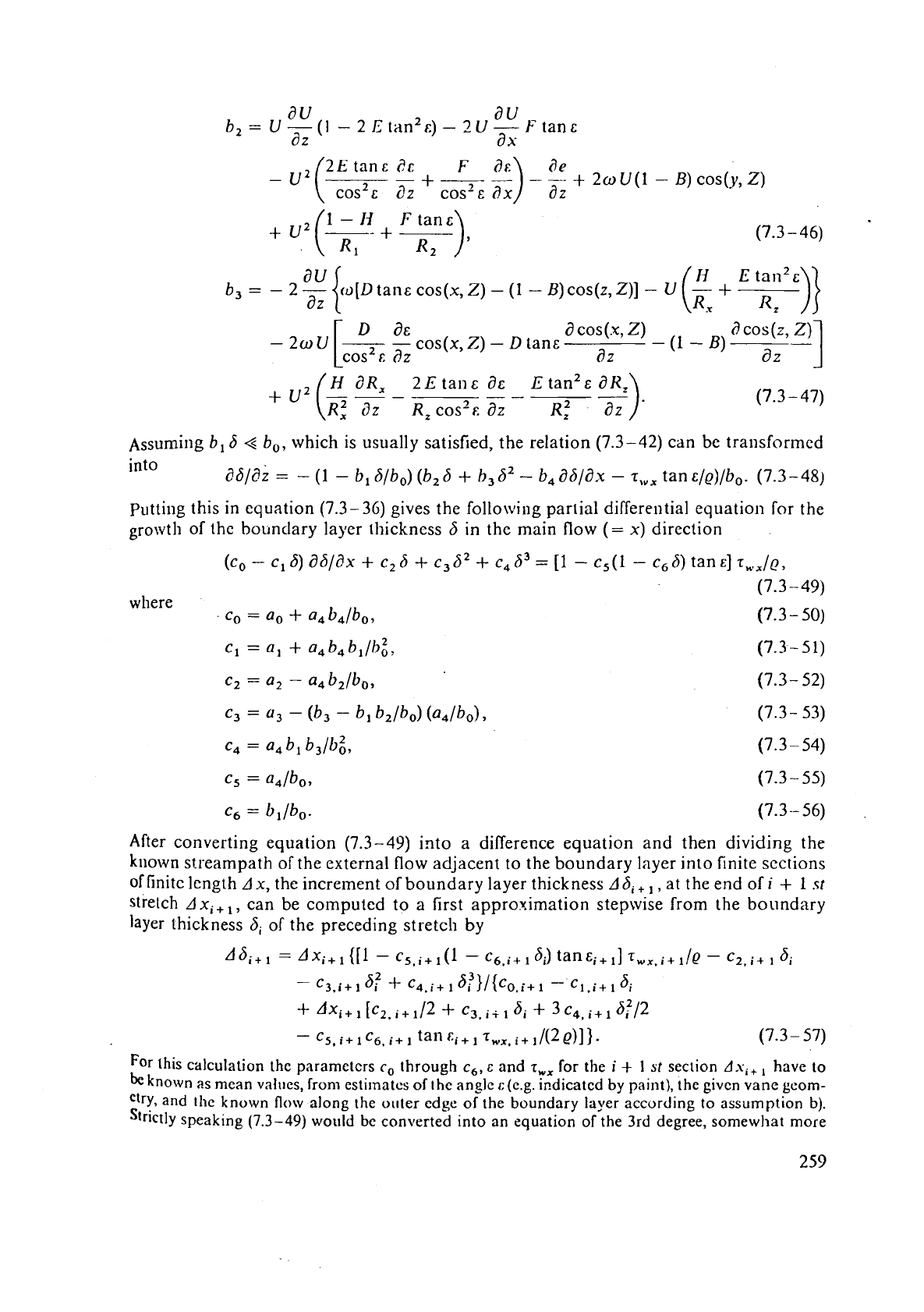
au
au
b2=
U-(1 -2Etan2c)--2U-Ftanc
az
ax-
D
a&
a
cos
(.x,
Z)
i)
cos
(z,
z)
-
2,
u
[,
-
cos(x,
-
.
tan,
-
(1
-
B)
cos
E
az
az
az
-1
~ssumillg
b1 6
4
b,,
which is usually satisfied, the relation (7.3-42) can be transformed
into
86/82
=
-
(1
-
b, 6/bo) (b26
+
h,d2
-
b486/ax
-
T,,,
tan
c/e)/b,.
(7.3-48)
putting this in equation (7.3-36) gives the following partial differential equation for the
of the
bountlary layer thickness
6
in the main flow
(=
x)
direction
where
Co
=
a0
+
a4b4lb0,
After converting equation (7.3-49) into a difference equation and then dividing the
kiiown streampath of the external flow adjacent to the boundary layer into finite sections
of
finite length
Ax,
the increment of boundary layer thickness
Adi
+
,
,
at the end of
i
+
1
st
stretch
Axi+,,
can be computed to a first approximation stepwise from
the
boundary
layer thickness
hi
of the preceding stretch by
For
this calculation the
parameters
r,
through
c,,
c
and
T,,
for
the
i
+
1
st
section
Asi+,
have to
be
known as rncan values, from estirnatcs of
t
he
anglc
c
(e.g. indicated by paint), the given vane geom-
cir~,
and the known
flow
along the outer edge of the boundary layer according to assumption b).
Strictly speaking
(7.3-49)
would be converted into an equation
of
the 3rd degree, somewhat more
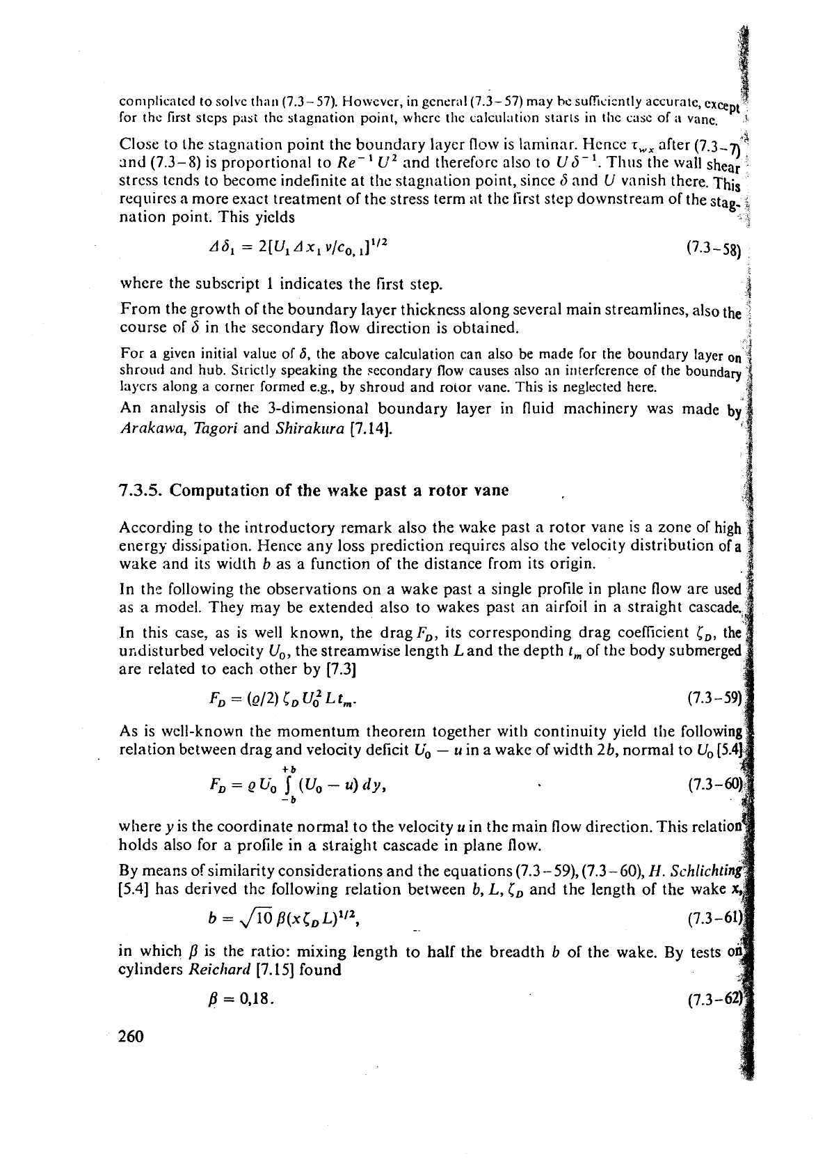
conlplicated to solvc th;ln (7.3-
57).
Howcvcr, in gcncral(7.3- 57) may hc sulfisicntly accurate,
exce
P'
,
for thc first stcps past the stagnation point, whcrc tl~c calculation starts in thc casc of
;I
vane.
-
*$
Close to the stagnation point the boundary layer
flow
is laminar. Hence
r,,
after
(7.3-7)
and
(7.3-8)
is proportional to
Re-
'
u2
and therefore also to
U
5-
'.
Thus the wall shear
.
stress tends to become indefinite at the stagnation point, since
5
and
U
vanish there.
This
requires a more exact treatment of the stress term at the first step downstream of the stag.
-1
nation point. This yields
A
3
ASl
=
2[U,
Ax,
v/co,
where the subscript
1
indicates the first step.
-i
From the growth of the boundary layer thickness along several main streamlines, also the
I
course of
b
in the secondary flow direction is obtained.
k
For a given initial value of
6,
the above calculation can also be made for the boundary layer
on
shroud and
hub.
Strictly speaking the ~econdary flow causes also an irlterfcrence
of
the boundary
layers along a corner formed
e.g.,
by shroud and rotor vane. This is neglected here.
An analysis of the 3-dimensional boundary layer in fluid machinery was made
by
Arakawa, Tagori
and
Shirakura
[7.14].
7.3.5.
Computati~n of
the
wake
past
a
rotor
vane
According to the introductory remark also the wake past a rotor vane is a zone of high
energy dissipation. Hence any loss prediction requires also the velocity distribution of
a
wake and its width
b
as a function of the distance from its origin.
In
ths following the observations on a wake past a single profile in plane flow are used
as
a
model. They may be extended also to wakes past an airfoil
in
a
straight cascade.,
In
this case,
as
is well known, the dragl;,, its corresponding drag coefficient
c,,
the
urdisturbed velocity
U,,,
the streamwise length Land the depth
t,
of the body submerged
are related to each other by
[7.3]
As is well-known the momentum theorern together wit11 continuity yield the following
relation between drag and velocity deficit
Uo
-
u
in a wake of width
2b,
normal to
Uo [5.4]
+
b
1
FD
=
ebb
J
(V,
-
U)
dy,
-
b
where
y
is the coordinate norma! to the velocity
u
in the main flow direction. This relatio
holds also for a profile in a straight cascade in plane flow.
By means of similarity considerations and the equations
(7.3
-
59),
(7.3
-GO),
H.
Schlichti
[5.4]
has derived the following relation between
b,
L,
ISD
and the length of the
b
=
fi
j?(xco
L)'",
--
in which
P
is the ratio: mixing length to half the breadth
b
of
the wake. By tests
o
cylinders
Reicltard
j7.151 found
/3
=
0,18.
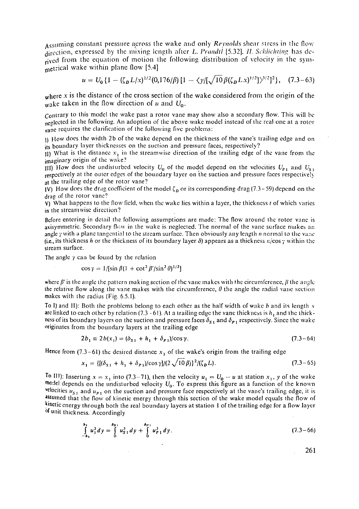
bss~rniing constant pressure aprnss the wake n~~d only
Rr~rrolrls
sl~eilr strcss
in
the
no\,-
dircctiOn,
expressed
by
the
nniuing Icnsth afier
L.
Pr-rrrlcttl
[5.32].
11.
Sc,l:llr./tri~~g
has
dc-
rived
froin the equ;~tion of motion
the
followi~lg distribution
of
velocity in
the
sym-
n,et;ical
wake
within plane
flo~il
(5.41
&ere
x
is
the distance
of
the
cross
section of the
wake
considered
froill
the origin
of
the
taken
in
the flow dircction
of
1,
and Uo.
Contrary to this model the wake past a rotor vanc may show also a secondary flow. This will
hc
,c_c~ected in the following.
An
adoption of thc above \vilkc model instead of the rcal onc at a rotcr
vane requires the clarification of the folloc~ing
fivc
problems:
1)
How docs the width
2b
of the wake depend on the thickncss of the vane's trailing cdge and on
its
boundary laycr thicknesses on
t
hc suction and pressurc faczs, respectively?
11)
LVhat is the distancc
s,
in the streamwise direction of the trailing edge of the vane from ths
imagiliary origin of the wake:'
111)
HOW
docs the undisturbed velocity
U,
of thc model depend on the velocities
U,,,
and
Us,
respc~ti~eIy at the outcr edges of the boundary layer
011
ihe suction and pressure faces respective!?
the trailing
ed9e of the rotor vane?
IV)
How
does the drag coefficient of the model
i,
or its corresponding drag (7.3-59) dcpcnd
on
the
drag of the rotor vane?
V)
What happcns to the flow field, \$.hen thc wakc lies within a laycr, the thickness
t
of which varies
in
the strcaniwisc dircction?
Before entering in dctail the fo1lov:ing assumptions are made: The flov: around the rotor vane is
~xisymnietric. Secondary
fl~;\v
in thc wakc is
neglected.
The normal of the vanc surface makes
an
angle
;.
with
a
planc tnngcntinl to the strcam surfncc. Then obviously any length
11
ncrlnnl to thc vanc
(i.e., its thickness
h
or the thickness
elf
its bolindary layer 6) appears as a thickness rijcos;. nithin thc
stream surface.
The angle
y
can be found
by
the relation
cosy
=
l/[sin
p(1
+
cot2 p/sin2 0)"2]
where/I1is the angle the pattern making section of thc vane 1nakc5 with the circurniercnce,
/j
thc anglc
the
rclat~ve flow along the vane makes with the
circumference,
0
thc angle the radial vallc scction
makes with the radius (Fig. 6.5.1).
To
I)
and
11):
Both the problems belong to each other as the half width of witkc
b
and its length
\
are linked to each othcr
by
rclation (7.3 -61). .4t a trailing edgc the vane thickness ic
/I,
and the thick-
ncss of its boundary layers on the suction and pressure faces S,, and
6,,
respecti~ely. Sincc the wake
originates from the boundary layers at the trailing edge
2b,
=
2b(x1)
=
(b,,
+
h,
+
G,,)/cosy.
(7.3
-
64)
Hence from (7.3-61) the desired distance
x,
of the wake's origin from the trailing edge
x,
=
{[(6,,
+
11,
+
6, ,)/cos
111/(2
J%/%J~/(CDL).
(7.3-
65)
To
II!): Illsert~ng
x
=
s,
into (7.3-71), then the velocity
u,
=
U,,
-
u
at station .u,,
y
of thc wake
model depends on the llndisturbcd velocity
U,,.
To express this figure as a function of the known
vciocities
11,
slid
I,,,
on the suction and pressure face respectively at the vane's trailing cdge, it is
'Ssurned that the flow of kinetic energy through this section of the wake model equals the flow of
lrinetic energy through both the real boundary layers at station
I
of the trailing edge for a flow layer
unit thickness. Accordingly
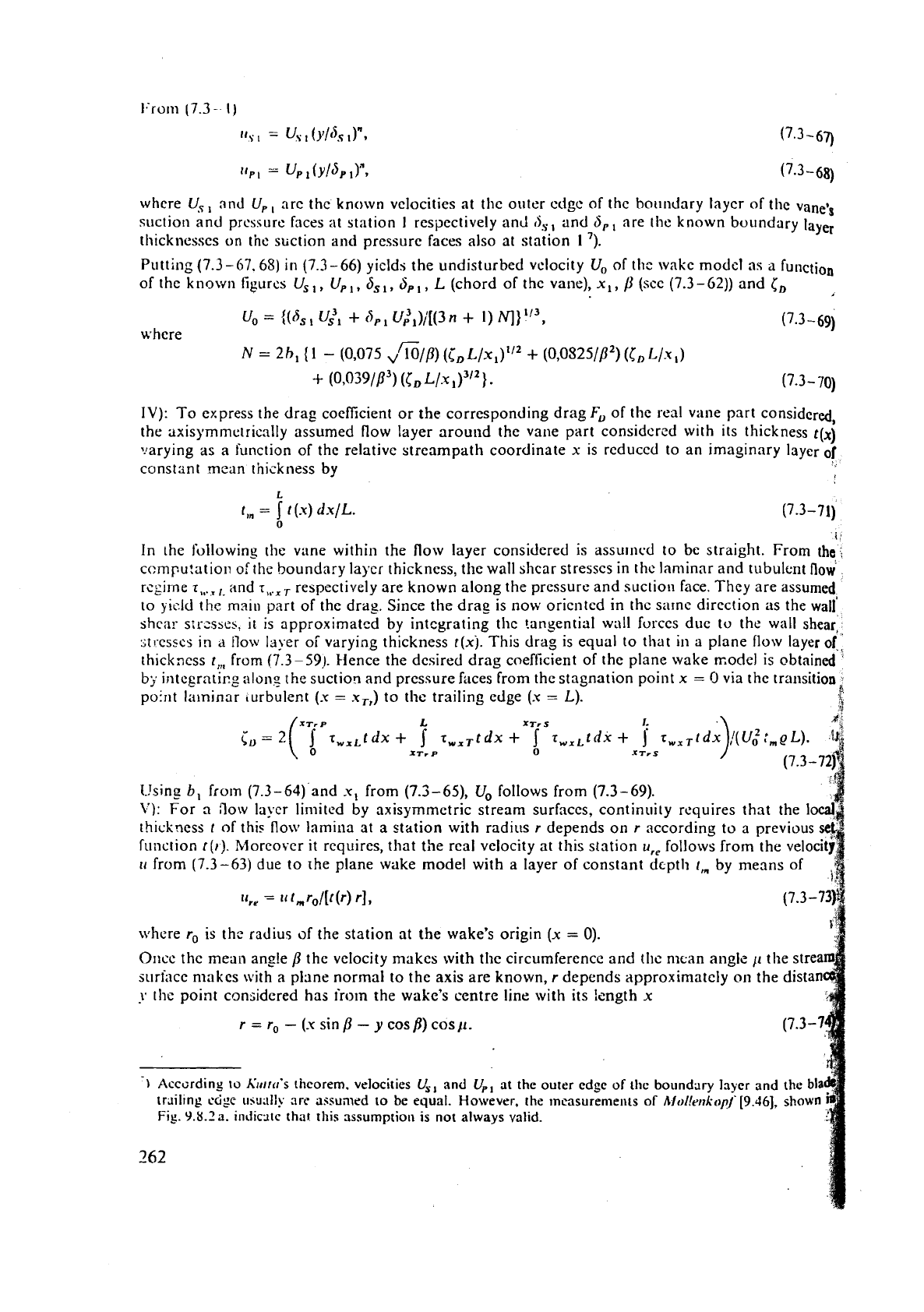
whcre
Uyl
and Up, arc thc known
velocities
at the outer cdgc of thc boundary Iaycr of the vane*s
suction and prcssurc faces at station
I
respectively and
0,
and
S,,
are the known boundary
layer
thicknesses
on
the suction
and
pressurc faces also at station
1
7).
Putting (7.3-67.68) in (7.3-66) yiclds the undisturbed velocity U, of the
model as
a
function
of the ktlown figures
US,,
Up,,
ds
,
,
SP
L (chord of the vane), XI,
P
(see
(7-3-62)) and
CD
i
uo
=
((6,
U,3,
+
Bp
u:1)/[(3
n
+
I)
NI)
'I3, (7.3 -69)
where
N
=
2hl
(1
-
(0,075
,,%/B)
(i,,
L/X,)'~~
+
(0,0S25/PZ)
(I,,
Llx,)
+
(0,039/P3)
(t;,
L/.X~)~/*}. (7.3-70)
IV):
To express the drag coefficient or the corresponding drag
FD
of the real vane part considered,
the
axisymmetrioally assumed flow layer around the vane part considcred with its thickness
t(~)
mrying as a function of the relativc streampath coordinate
x
is rcduccd to an imaginary layer
of
constsnt rnzan thickness by
L
t,,
=
j
t
(.K)
dx/L.
0
I
In thc following the vane within the flow layer considcred is assur~lcd to be straight. From the
computation of
the
boundary laycr
thickness,
the
wall
shcar stresses in thc laminar and tubulent flow
rcgirne
r,,..
,
and
I,,.,
,
respectively are known along the pressure and suction face. They are assumed
to yicld
the
malu part of the drag. Since the drag is now oriented in the sarne direction as the wall'
shcx
sir-sses,
it
is approxirnatcd by
integrating
the tangential wall furccs due to the
wall
shear,
;[I-csscs
In
a
llow
Id)er oi varying thickness t(x~. This drag is equal to that in
a
plane flow layer
of",
thickness t,, from (7.3-59). Hence the desired drag coefficient of the plane wake model is obtained
by
irltcgrnticg alons the suctiorl and pressure faces from the stagnation point
x
=
0
via the transition
po:nt laminar turbulent
(.Y
=
x,,)
to the trailing edge
(.K
=
L).
!
3
(.!sing
b,
frvln (7.3-64) and x, from (7.3-65), Uo follows from (7.3-69).
\'I:
For
3
flow lvcr limited by axisymmetric stream
surfaces,
continuity requires that the lo
thickness
t of thi~ flow lamina at a station with radius
r
depends on
r
according to a prev
fi~tlction to). Morcovcr it requires, that the real velocity at this station
ur,
follows from the
u
from (7.3-63) due to rhe plane wake model with a layer of constant dcptli
t,
by means o
5
nrliere
r,
is thc radius
of
the station at the wake's origin (x
=
0).
OIICL' the mean ang!e
P
the velocity makes with the circumference and tllc mean angle
p
the stre
suri;~ce makes with
a
plane normal to the axis are known,
r
depends approximately on the distan
y
thc point considered has irorn the wake's centre line with its length
x
r
=ro
-(xsinp
-ycos/3)cosp.
-1
According
to
K~hirrrtr's theorem, velocities
U,,
and
Up,
at the outer edge
of
the boundary layer and the bla
tr~ilrng
ccige
u\u.~l:!
are
assumed
to
be
equal. However, the lnsasurenlents of
Alol!errk(>p/!l'[9.46],
sllown
Fig. 9.8.2a. ~ndlc.~tc that this assumptioil is not always valid.
262
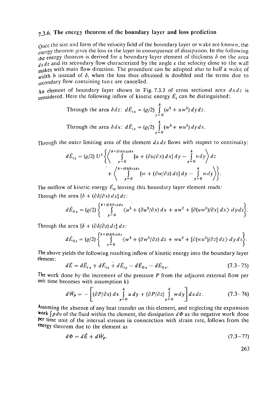
7
3.6.
Tlie energy
theorem
of
the boundary Inycr and loss prediction
ollcc thc size and form of the velocity
ficld
of the boundary layer or wake are kno~vn. the
,,,crgy thcorern gives
the
loss in tlie layer in consequence of dissipalion. In the follo~vin~
,he
energy theor-cm is derived for-
a
boundary lapcr clement of thickness
d
on
the
area
dx
JZ
and its secondary flow cl~araclerized by the angle
E
the velocity close
LO
the wall
with main flow direction. The procedurc can be adopted also to half a wake of
,idth
b
instead of
6,
when
the
loss thus obtained is doubled and the terms due to
Secondary
flow
containing tan
f:
are cancelled.
4n element of boundary layer shown in Fig.
7.3.3
of cross sectional area
dxd;
is
considered. Here the following inflow of kinetic energy
I?i
can be distinguished:
6
Through the area
adz:
dEi,
=
(~12)
(2r3
+
IIM~~)
dydz.
y=O
6
Through the area
6rl.x:
diiz
=
(~/2)
5
(w3+ wu2)
dj'dx.
y=o
~hrough the outer limiting area of the element
dxdz
flows wit!l respect to continuity:
The outflow of kinetic energy
Eo
leaving this boundary layer eleinent reads:
Through the area
[6
+
(ahlax) dx]
dz:
Through the
area
[6
+
(a6/8z)
dz] d-u:
a+(3s/ar)dz
0
=
(2
{
j
(w3
+
(dw3/dz)
dz
+
nu2
+
[i(liu2)/d;] dz)
)'
=
0
The
above yields the following rcsulting inflow of kinetic energy into the boundary layer
clement
:
dB
=
dl?,,
+
dEi,
/
dEi,
-
dd0,
-
dEo,.
(7.3
-
75)
The
work done
by
the increment of the pressure
P
from the adjacent external flow per
unit
time becomes with assumption
k)
Assuming the absence of any heat transfer on this element, and neglecting the expansion
work
JPdv
of the fluid within the clement, the dissipation
d@
as
the negative work dope
Pr
time unit of the internal stresses
in
conncection with strain rate, follows from the
theorem due to the
element
as
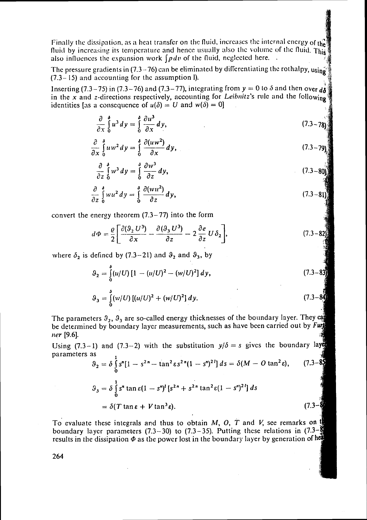
Finally the dissipr~ti~n, as
a
heat transfcr on
thc
fluid, increases !hc iriternal cnergy
of
e
fluicl
by increasing
its
tenipcrature and hencc usually also thc \olutnc
of
tflc fluid.
~hii
also influences the expansion
work
Ipdv
of the fluid, neglected here.
.
The pressure gradients
in
(7.3
-76)
can
be eliminntetl by dirferentiating thc rothalpy, usin*
(7.3-
15)
and accounting for thc assumption 1).
g
Inserting (7.3
-
75) in (7.3-76) and (7.3- 77), integrating from
y
=
0
to
d
and then over
d6
in the
x
and z-directions respectively, accounting for Lrib~titz's rule and the following
identities
[as
a
consequence
of
46)
=
U
and w(S)
=
0)
convert the energy theorem (7.3-77) into the form
'.I
where
6,
is defined by (7.3-21) and
9,
and
9,,
by
a
8,
=
~(II/u)
[l
-
(II/U)~
-
(w/U)~]
dy,
0
The parameters
3,,
3,
are so-called energy thicknesses of the boundary layer. They
be determined
by
boundary layer measurements, such as have been carried out by
F
114r
[9.6].
Using
(7.3-
1)
and (7.3-2) with the substitution
y/6
=
s
gives the boundary la
parameters as
1
9,
=
6
lsn[l
-
s2"- tan2~s2n(1
-
s'')~']
ds
=
S(M
-
o
tan2&),
(7.3-
0
1
3,
=
5
isn
tan~(1
-
s")l [s~~
+
sZn
tan2&(1
-
s")~'] ds
0
=
S(T
tan
E
+
V
tan3&).
T;
evaluate these integrals and thus to obtain
M,
0,
T
and
V,
see remarks on
boundary layer parameters (7.3-30) to (7.3-35). Putting these relations in
(7.3-
results in the dissipation
@
as
the power lost in the boundary layer by generation
of
h
264
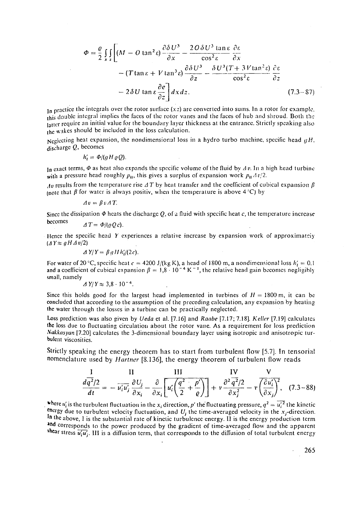
dhu3
IS
u3(T+
3
lftan'c)
?c
-
(T
tan
r:
+
V
lan3c)
-
-
-
d
z
cos2
c
82
ln
practice thc integrals ovcr the rotor surface
(s:)
arc converted into sums. In a rotor for exnmp!~.
this doublc i11tegr;ll implies the faces of thc rotor vanes and the faces of hub and shroud. Both t!~r
laltcr rcquire
an
initial value fur rhe boundary layes thickness at the entrance. Strictly spzaking also
*>lkes should be included in the loss calculation.
~~~lccting heat expansion, thc nondimensio~sl loss in a hydro turbo machine, specific head
qp.
discharge
Q,
becomcs
h;
=
@/(gH@Q).
In
cxact terms,
@
as heat also expands the spccific volume of the fluid by
d
v.
111 a high head turbinc
with
a
pressure head roughly
y,,,
this gives a surplus of expansion work
p,,
.3
r/2.
,lo
results from the tcmpcrat~lrc rise
AT
by heat transfer and the coefficie~~t of cubical expansion
/I
(note
that
p
for watcr is alivays positiv, whcn thc temperature is above
4°C)
by
Since the dissipation
Q,
hcats the
discharge
Q,
of
a
fluid with spccific heat
c,
the temperature increase
becomes
AT= @/(_oQc).
Ilcnce the spccific head
Y
experiences
a
relative increase by cxpansion work of approximatciy
(AYz
gHAv/2)
A
Y/Y=
pgIIh;/(2c).
For watcr
of203C,
specific hcnt
c
=
4200
J,'(kg
K),
a head of 1800 m, a nondimensional loss
h;
.=,
0.1
and
a
coefficient of cubical cxpansion
/I
=
1,8
.
K-',
thc relativc head gain bc.comcs negllgrbl)
small, namely
A
Y/YZ
3,8.
IO-~.
Since this holds good for thz largest head implemented in turbines of
I1
=
1800 m,
it
can be
concluded
that according to the assumption of the preceding calculation, any expansion by heating
the water through the losscs in
a
turbine can be practically neglected.
Loss prediction was also
givcn by
Uedu
et al. [7.16] and
Ranbe
[7.17; 7.181.
Kellcr
(7.191 calculates
lhc loss due to fluctuating
circulatioil about the rotor vane. As a requirement for loss prediction
Nakkns~un
17.201 calculates the
3-dimensional
boundary layer using isotropic and anisotropic tur-
bt~lcllt viscosities.
Srrictly speaking the energy theorem has to start from turbulent
flow
[5.7].
In tensoria!
n@menclature used
by
I-lurtner
[8.136],
the
energy
theorem of turbulent
flow
reads
-
,
~hcre
tri
is the turbulent fluctuation in the xidirection,pl the fluctuating pressure,
qz
=
uiZ
the kinctic
rncrgy
due to turbulent velocity fluctuation, and
U,
the time-averaged velocily in the xi-direction.
In
the above,
I
is the substantial rate of kinetic turbulence encrgy.
I1
is the energy production tcrm
"orrcsponds to the power produccd by the gradicnt
of
time-averaged flow and the ripparcnt
'h~r stress
q..
111
is a diffusion term, that correspol~ds to the dillusion of total
turbulent
energy
To
simplify the prohletn.
ill
the
cosc
of striiight pipc
flow,
tllc appilrent shear stress,
according
to
a
propo5al
oi
~~~LI.S.S;IT~.S~
[5.41,
is
rctl~!ced to
an
eddy viscosity
c:
by
The mixing Iensth
l.,
introduced
by
Proti$rl,
is expressed. ;iccording
to
Nili~lrodse
[7.211,
in terms
(;f
the
distance from the pipe axis, in
a
pipe
of
radius
R
by
LiR
=
k,
+
k,(r/~)~
+
k,(r/R)j.
(7.3
-
90)
PI-un(lt1
introduced a
Reyl~olds
number
duc
to
turbulence
as
Re,
=
(q2)1i2
L/v.
(7.3-91)
To
predict the loss coefficient
of
a
channel in unsteady flow,
Wisiliev
and
Kvo~
[7.22]
postu1;ited
the
eddy viscosity to be the following function
of
Re,,
and the empirical con-
"
stants
ki,
c,'v
=
k,
Re,(l
-
e-k3Re:
+
k4
I?e,?l2
e-ksXe:).
(7.3-92)
1
According to
a
proposal
of
Pra~ztltl [7.23]
and
Kolnzogort?ff[7.24]
the relevant diffusion
-
term with
thu
radial fliictiic?tion
t.'
can
be
sin~plified as follows:
a
f
t
where
k,
is
:In
empirical constant. For thc dissipation tcrn~,
Vnsiliev
and
Kvon
used
thc'!
expression
[7.22]
s3
-
0
=
-
k,(v
+
k,~)
Lq2/2.
A
comparison of this thcory with real effects can be rnade o~~ly,
if
the apparent shear stresses
arc
mertsurctl.
In
a gcneral :~nstt.ady flo\\; this is rather troublesome. On the basis of experirnen
a
turbulent pulsnting pipe
flow
carried out by
Kil-r~lse
I8.1351,
Hrirtnrr
recently succeeded in co
paring the
ccidy
1-ircosit;:; mcasurcd by using a laser system with two beams at
YO'
inclined plan
\\.it11
ihc
eddy
\.iscosity from Zk.silirl*'s and Kvott's theory [8.136].
As
a
resuit. he states that agrecnlcnt exists only
st
weak pulsation arrlplitudes (compared with
t
time-averaged flow). and at
Rrj.t~oltls
numbers larger than 10"better
lo6).
In an
example
calculat
bj
H~rtnrI-
for the radiils range
I-/R
=
0,6 to
?,87,
the calculatec! value of
E
is about
25%
below
t
~neiisured one. Towards the axis this increases
up
to 30%. Towards the pipe wall the dcviati
beccmcs yet largcr.
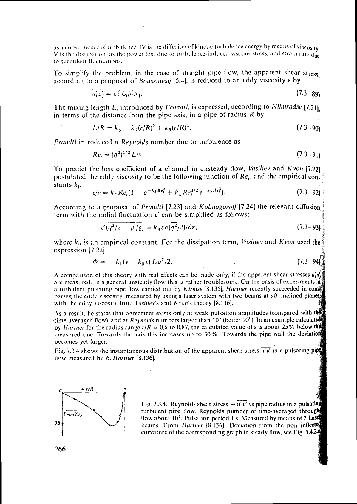
Eg.
7.3.4
shows the instzntaneous distribution of the apparent shear stress
u'u'
in a pulsating pi
flow
~neasurcd
by
E.
Hclrtr~er
[%I 361.
-
r/R
Fig.
7.3.4.
Rcynolds shcar stress
-
rr'
vs
pipe radius in
a
pulsat
turbulent pipe
Sow.
Reynolds numbcr of time-averaged thro
flow about
lo5.
Pulsation period
I
s.
hlcasured
by
means of
0.5
bcarns. From
Htrrttri*r
[5.136].
Deviation from the non
i
curvature of the corresponding graph in steady flow, see Fig
266
