Raabe J. Hydro power - the design, use, and function of hydromechanical, hydraulic, and electrical еquipment
Подождите немного. Документ загружается.

tllc
I~~t~al spiral-formed main and its nozzle pipes. Thcn a
component
of penstock vclocity has a
nlorncnt abo111 the nozzle pipc axis
and
hcncc tcnds to gencrntc a strc:rnl\irisc VOI-ttcity thcrc.
sjncc in the no7zle the whole nct hcad of thc
turbine
is convertccl into ki~ictic encrgy. the largtst
str;,in raie of the main
flow
and hcncc also of vortices in the main flow
direction
occur.; [!]ere. Thus
according to (7.3--5) the kinetic energy of thcsc vortices is
increased
and then lost to en;tblc work
bc
done (Fig. 7.2.1~). After Krause, strcamwise vorticity may disappear by streamwise
a,cclerntion-
From this it cal: be secn that acceleration of main flow is not always a means of lowering losses.
7.2.2.2.
Dislocation
and
lengthening
of
a
vortex
within
a
bend
consider a plane potential flow in
a
channel of rectangular cross section (Fig.
7.2.2).
It
flows fro:n a straight channel into a bend of curvature
l/R,
R being largc compared wit13
.
the wicltl~
ll.
Ilnagine that
a
vortex, vorticity
a,,
enters the
bend,
norma! to the stream-
lines. Consisting always of the same
fluid
particles, it is surrounded
by
a free vortex where
the mean angular velocity of fluid elements, normal to each other. vanishes.
~hus at the bend's inlet the vortex is along
a
fluid region, of length
I,
(Fis.
7.2.2), normal
to
n
fluid element
l2
in the main flow direction. Within the bend, at a station where the
streanlwiss oriented element
1,
makes now an angle
dr:
with its initial directioil, the
elcment
1,
norrnal to
it
inust turn by
-
dc
from its initiai position. Hence this element
and
consequently also the vortex tube
make
an angle 2
tlc
with the cross section, that is
inclined by
dc
to the inlet of bend. This follows from the free vortex enclosing the vortcx.
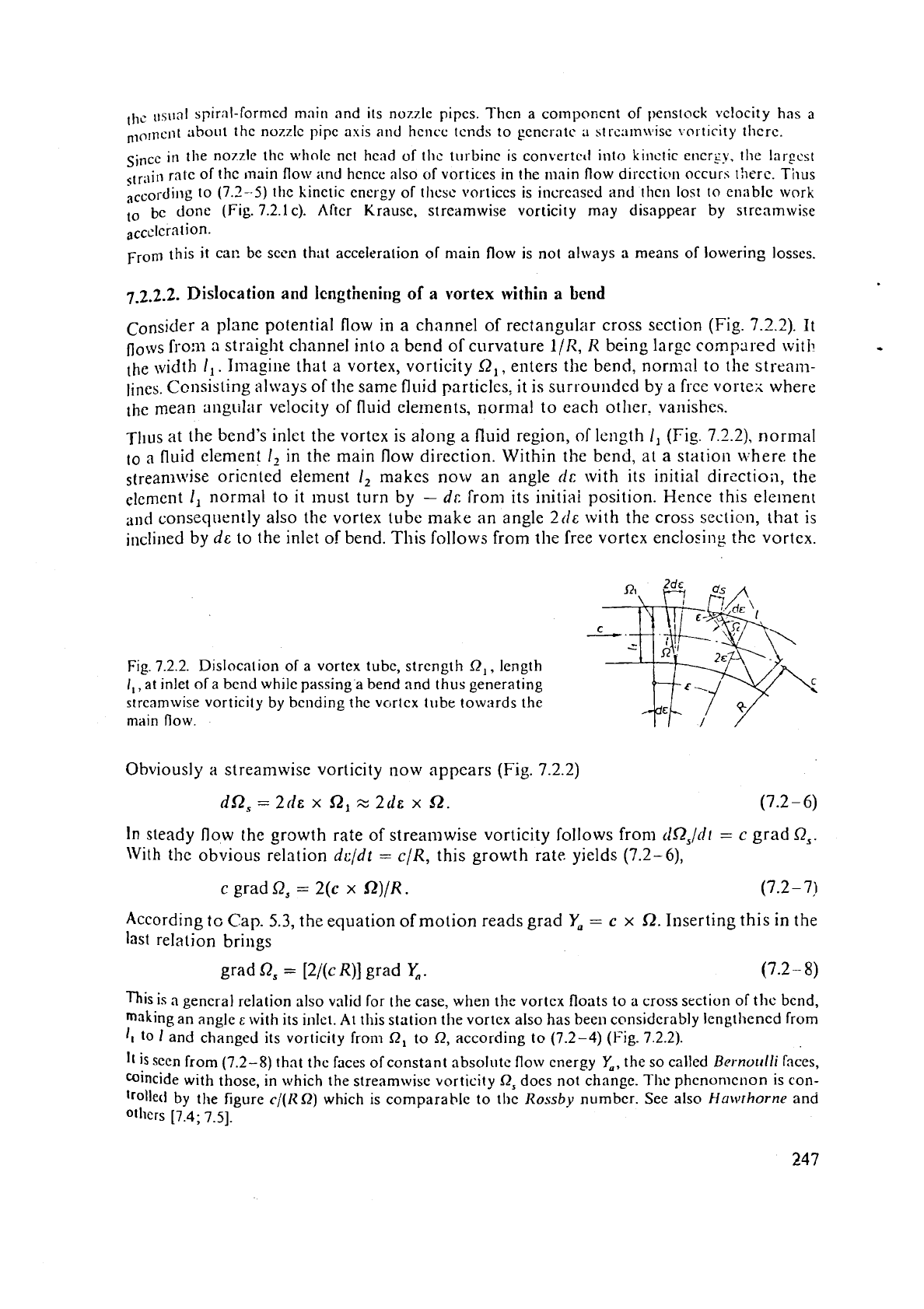
Fig 7.2.2. Disloca~ion of a vortex tubc, strength
R,,
length
I,,
at inlet of a bend while passing a bend and thus generating
strcamwise vorticity by bending the
vortcx tube towards the
main
flow.
--
Obviously
a
streamwise vorticity now appears (Fig. 7.2.2)
dn,
=
2de
x
SZ,
z
2de
x
St.
(7.2-6)
In
steady flow the growth rate of streamwise vorticity follows from
tlR,/di
=
c grad
Q,.
With the obvious relation
dcldt
=
c/R, this growth rate yields (7.2-6),
c grad
Q,
=
2(c
x
f2)/R.
(7.2
-
7)
According
tc
Cap.
5.3,
the equation of motion reads grad
Y,
=
c
x
St.
Inserting this in the
last relation brings
grad
QS
=
[2/(c R)] grad
Y,.
(7.2
-
8)
This is a general relation also valid for the case, when the vortcx floats to a cross section of thc bcnd,
making an angle
E
with its jnlet.
At
this station the vortex also has been col~sidcrably lengthened from
1,
to
1
and changed its vorticity from
R,
to
Q,
according
to
(7.2-4) (Fig. 7.2.2).
is seen from
(7.2-8)
that the faces of constant absolute flow energy
Y,,
the so called
~ernoulli
faces,
mincide with those, in which the streamwise vorticity
Q,
does not change. The phcnomcnon is con-
lrolletl by the figure
c/(R
R)
which is comparable to thc
Rossby
number. See also
Howrhorne
and
O~Ilcrs
[7.4;
7-51.
7.2.2.3.
Tllc
Irngtl~cning
of
3
vortes
tube
within
3
rotor
Considcr the study pl:l!i~ ~clntive
Oow
of
:lo idc:ll
fli~i~l
ill
il
striiigllt rccteilyulilr chanllel,
rotr~ting with constant ;ingular vclocity
(I)
(Fig. 7.2.3). 7'11~ normnl to tile plane of the main
flow
makcs
an
angle
11
wit11 the
xis
of
rotation. Under an :issunled irrot;~tional ;lbsolute
flow, the relative eddy has the relevant componct~t 2cr, cos
11
rlor~nal to the
flow
plane.
The r:~eridio~~rtl comporle~lt of relntivc eddy 2
to
sir1 11 obviously has
a
component
2"
sin 11
sin
in
the direction of the main flow, which n1;lkes
a
constant allgle
/I
with
the
pcriphcry. Considcr
a
vortex tube
c:f
vorticity
SZ,
and
lciigth
!,
,
norrnal to the main
flow
at cl~antlzl inlet (Fig. 7.2.3a). At an arbitrary instant later this vortex tube of length
I
makcs
an angle
E
with the chaaricl width and an angle n/2
-
c
with
w,
the relative velocity.
Suppose it has
a
vorticity
Q
in tl~c stationary frame of reference.
-
-
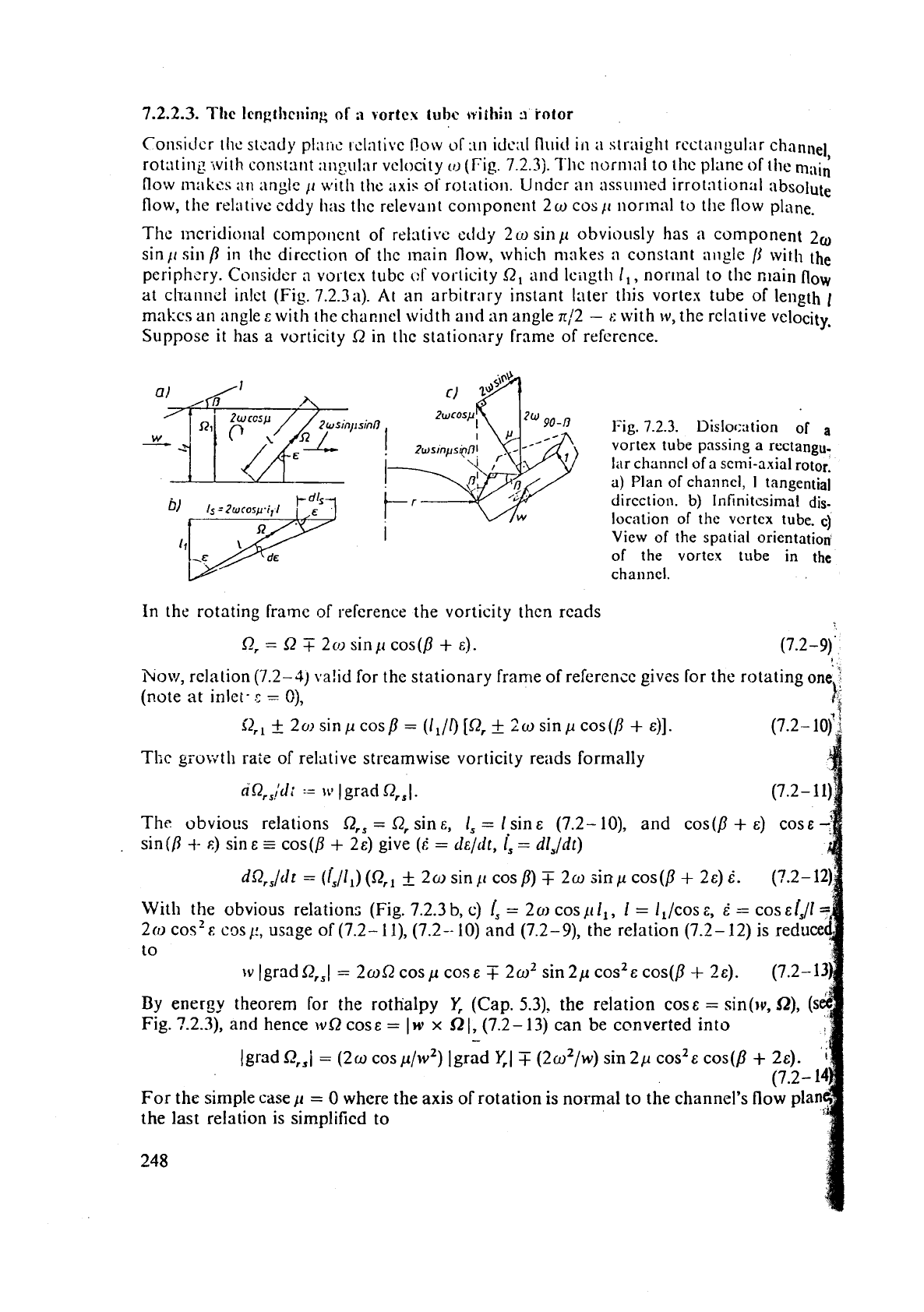
Fig.
7.2.3.
Disloc:~tion of
a
vortex tube passing a rectangu-
lar
channcl of a semi-axial
rotor.
a)
Plan of channel,
I
tangential
direction.
b)
lnfinitcsimal dis-
location of the
vertcx tube.
c)
View of the spatial orientation
of the vortex tube
in
the
channcl.
In the rotating frame of reference the vortioity then reads
how, relation (7.2-3) ra!id for thc stationary frame of reference givss for the rotating one
1
(note
at
inlct-
c
=
C),
r
i
Tkc
grvwtli rate of relative streamwise vorticity reads formally
fl'Qrs,!'J:
:=
\v
(grad Qr,l.
(7.2-
1
I)%
The obvious relations
S2,,
=
Q, sins,
I,
=
1
sin s (7.2-
lo),
and cos(p
+
E) cosc
sin
(0
4-
s)
sin
E
-
cos
(fi
+
2~) give
(i
=
d~/dr,
is
=
dl,/dt)
d9r!,,/cir
=
(/,/I,) (I?,,
f
20 sin11 cosp)
T
20
sinp
cos(P
+
2~)
6.
(?.2-12)
With the obvious relations (Fig. 7.2.3
b,
c)
is
=
2
o
cos
11
I,,
I
=
l,/cos
E,
6
=
cos
&f,/l
20)
cos'
C:
cos
11, usage of (7.2-
1
l), (7.2
--
10) and (7.2-
9),
the relation (7.2
-
12) is reduce
to
~Igradf2,,1
=
2mQcosp coss
T
2m2 sin2p cos2scos(p
+
28).
(7.2-13
By energy theorem for the rothalpy
Y,
(Cap.
5.3).
the relation coss
=
sin(~v,
SZ),
(s
Fig. 7-23), and hence
wS2
cos
E
=
1
w
x
52
1, (7.2- 13) can be converted into
-
lgrad QrSi
=
(2~ cosp/w2) [grad
Y,I
T
(2w2/w) sin 2p cos2& cos(p
+
24.
'i
(7.2-
For the simple case
C(
=
0
where
the
axis of rotation is normal to the channel's flow pla
the last relation is simplified to
248
grad Q,,
=
(2w/w2) grad
1;.
(o/Q
appears as the decisive number. From this it is
sci::~.
that now the strea:n\\.ise
relative vorlicity remains constant on faces of constiin: "rc.tl~;ilpy"
1;
=
p!~
+
gh
+
,,2/2
-
r2m2/2 [7.6; 7.71. The latter taken witho\it internal cner;:)f
term.
7.2.2.4.
Generation of secorldary flow
past
;1
cascade
consider
a
straight cascade (Fig. 7.2.4) passed
by
a plane poterrtirtl
flo\v.
At
st
ntion
1,
,ptrearn of the cascade. at
a
certain instant, a vortex line. 1cng:ll
I,
is normal to the maill
flow and between two streamli~ies, which pass thc stagnation poit~:.,
(IT
;uro
r.r.ieh bourinz
At station
1
this vortex has intensity
a,.
dow~istrearn
o!
t:i-
.c:issadc.
at
sta-
tion
2
it has length
I,
and
intensity Q,, with
a
streamwise cornpo1:eni
!j2,.
-l'lle
latter is
a
source of sccondlily Ilow generated by the rnai~i flow, when passing tlirough the cascade.
Fig.
7.2.4.
Dislocation of a vortex tube and the gencra-
lion olst~~~lwise vorticity
if
passing through
a
straight
cascade.
CC,
and
A,A,
are straight lines infinitesimally
long.
The velocities w,, w, with their angles
/I,, /I,
with the
circumference
at stations
1
and
2
are known from the velocity triangles. Consider a strip enclosed in the stream lines.
touching the suction and pressure faces of two
neighbouring profiles
of
the cascade. The
one streamline A A,A, A,
B
along the pressure face
(P)
of the upper profile, and the other
streamline
C
C, C2 C,
D
along the suction face
(S)
of the lower profile.
The
points
A,
C
in front of the cascade and
B,
D
past the cascade mark the pocitions of
the
vortex line's ends
when
it passes through stations
1
and 2, in front of and downstream
of
the cascade. The sections
A,
A, and CC, as also
A,
B
and C,
C,
for congruity are
covered in the same time intervals. Furthermore the fluid covers the stretch
AA,
=
!
cosp, (Fig. 7.2.4) with the velocity w, and the distance C3
D
=
x
with the velocity rv,.
The
time intervals, the fluid necds to cover the suction face
(S)
and pressure face
(P),
rzsult
from the respective contour velocities (known for example from cascade theory) by
The
time intervals, to cover the distances AA,
and'^,^,
are
The obvious cquality
T,,-,
=
T~-,,
gives
.
.
Obviously tllc angle
E
the \lortex makes with a normi11 to the strearnlilie p:tst the Cascade
follo\vs from
sin
c
=:
(s
-
t
cos /?,)/l,.
(7.2
-
20)
With the relation
I,
=
r
sin
fl,
,
the relation R2
=
Q,
1,/1,
frorn (7.2-4), the desired stream-
wise vorticity past the cascade
SZ,,
=
SZ,
sin
E
follows from
(7.2-20)
as
Q,,
=
(x
-
t
cos P2) Q,/(r sin
PI).
(7.2- 21)
Introducing
a,
=
t,
sin
/I,,
assuming the depth of flow layer to be
'l',
Stokes'
theorem
(Cap. 5.2) gives the circulation due to
secondary
flow about the cross section of the strip
considered past the cascade as
G,
=
n,
(sin /?,/sin fl,) [w2(TP
-
7,)
-I-
t(w2 co~/?,/w,
-
Cos P2)].
(7.2-22)
Sec also Ha\rlthorne (7.41, and Squire [7.5].
7.2.2.5.
The
streamwise vorticity past a
radial
flow
impeller
Many reasons may exist for the streamwise vorticity past a radial flow impeller. The one
considered here is the peripheral oriented vorticity entering the impeller eye from the
boulidary layer of the suction line, dcrioted by R,.
Consider a vortex line covering the pitch at impeller inlet, length I,, vorticity
8,
(Fig.
7.2.5).
Downstream of the impeller it has length
I,
and absolute vorticity Q, and
makes an angle
E
with the width
a,
of
a strip that extends over one pitch.
In
the following
'
the
absolute velocity dow~istream of the impeller is assumed to
be
steady.
..$
The absolute flow there makes an angle a, with the periphery known
triangles. Hence the
streamwise vorticity of the absolute flow there as
frorn
a
ful
streamwise vorticity R,, arid that norrnal
to
it
a,,
due to relative flow (Fig. 7.2.5) is
give
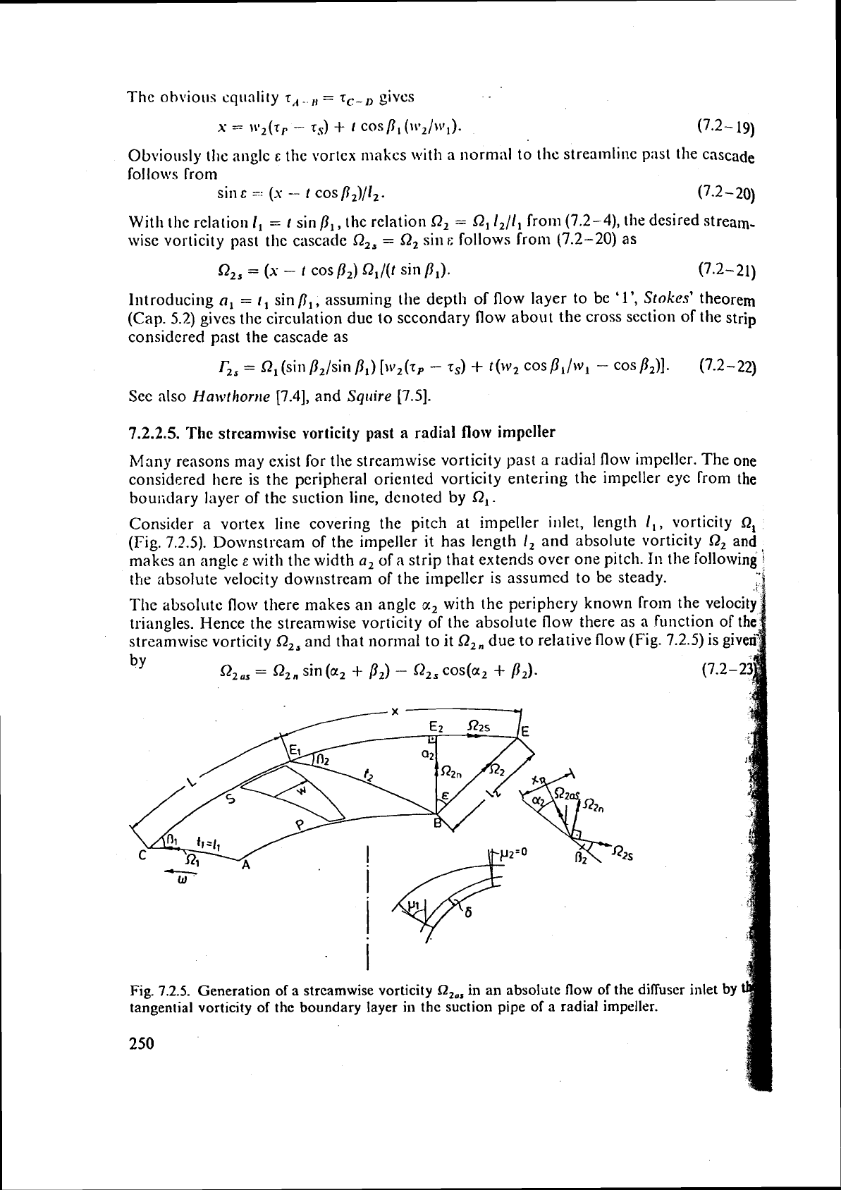
Fig.
7.2.5.
Generation
of
a
streamwise vorticity
Q,,,
in an absolute flow
of
the diffuser inlet
by
tangential vorticity of the boundary layer in
thc
suction pipe
of
a
radial impeller.
To
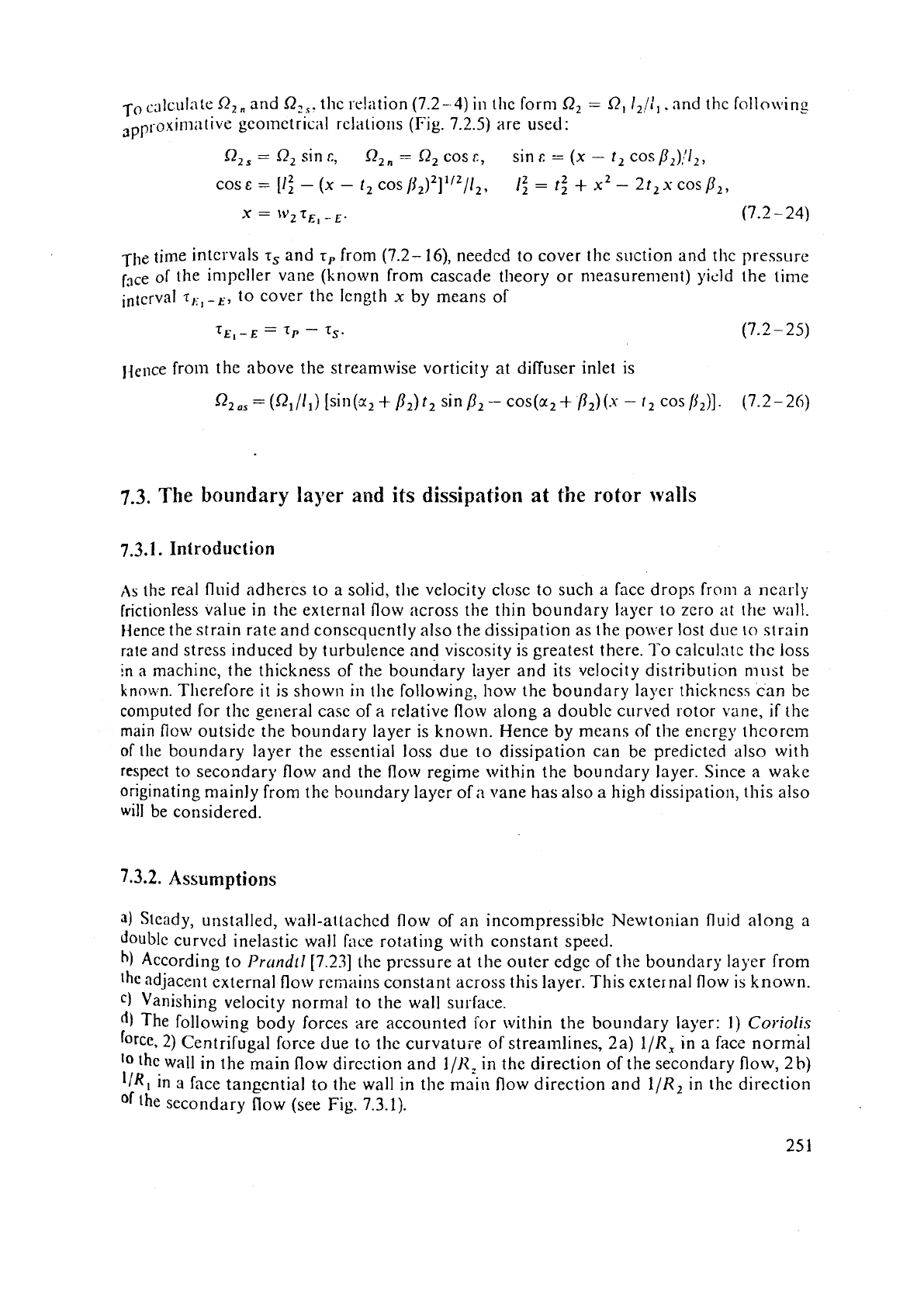
c:~lci~l;ite
R2,
and Q,,. thc re!ation (7.2-
4)
in
the form R,
=
R,
I,!:,
.
and thc lollo\ving
,pproxin~;itivs geotnetrical rclatio~is (Fig. 7.2.5) are used:
R2,
=
Q2 sin
c,
Q,,
=
Q2 cosc, sinf:
=
(x
-
t,
cos/3,)/12,
21/21
12-
2
cosE=[I;-(x-f2cosp2)]
1,
2-t2+x2-2t2~~~~P2,
x
=
1v2
T~,
-E.
(7.2
-
24)
The time
intervals
7,
and
r,
from (7.2- 16), needed to cover thc suction and thc pressure
face of the impeller vane (known from cascade theory or measurement) yield the time
interval
T,;,-E,
to cover the lcngth
x
by means of
Ijence fro111 the above the streamwise vorticity at diffuser inlet is
Q2.,
=
(Q,/l,) [sitl(a,
+
/I,)
t, sin
b2
-
cos(a2
+
P,)(s
-
t2
cos
[j,)].
(7.2-26)
7.3.
The
boundary
layer
and
its
dissipation
at
the
rotor
walls
7.3.1. Introduction
,IS
the real fluid adheres to a solid, the velocity close to such a face drops from a ncarly
frictionless value in the external flow across the thin boundary layer to zero at the wall.
Hence the strain rate and conscqucntly also the dissipation as the pon.er lost due
lo
strain
rate and stress induced
by
turbulence and viscosity is greatest there. To calcul~tc the loss
in
a
machine, the thickness of the boundary layer and its velocity distribution must
be
known. Therefore it is show11 in the following, how the boundary layer thickncsc can be
conlputed for the general case of
a
relative flow along a double curved rotor vane,
if
the
main
fiow outside the boundary layer is known. Hence by means of the energy thcorc~n
of the boundary layer the esscntial loss due to dissipation can be predicted also with
respect to secondary flow and the flow regime within the boundary layer. Since a wake
originating
mainly from the boundary layer of
a
vane has also a high dissipation, this also
will
be considered.
7.3.2.
Assumptions
3)
Sleady, unstalled, wall-attachcd flow of an incompressible Newtonian fluid along
a
double
curved inelastic wall face rotating with constar~t speed.
h)
According to
Prandtl
[7.23] the pressure at the outer edge of the boundary layer from
adjacent external
flow remains constant across this layer. This external flow is known.
C)
Vanishing velocity normal to the wall surface.
The following body forces are accounted
for within the boundary layer:
1)
Coriolis
2)
Centrifugal force due
lo
the curvat~ie of streamlines, 2a) 1/R, in a face normal
'0
[hc
wall in the main flow direction and 1/R, in the direction of the secondary flow, 2
b)
IIR1
in
3
face tangential to tlle wall in the main flow direction and
1/R,
in the direction
the
secondary flow (see Fig. 7.3.1).
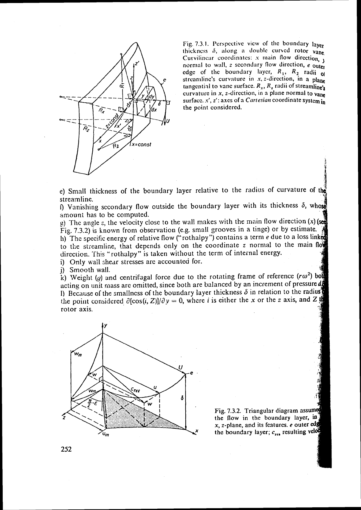
Fig.
7.3.1.
I'crspcctivc vicw of the boundary
layer
thickness
6,
along
;I
d011blc curhcd rotor
vane
Curvilir1c;ir
coordinates:
s
main
now
direction
,)
normal to
w:lll,
z
secondary
flow
direction,
e
outer
edge
of
tlic boundary laycr,
R,,
Rt
radii
01
strcamlinc's curv;lturc
in
.x,
z-dircct~on, tn a
plane
tangential
to vanc surface.
R,,
Hz
radii
of
streamiinevs
curvsturc
in
x,
z-direction,
in
a
plane
normal to
vanc
surracc.
.u',
z':
axes of
3
Cortesiat~
coordinate system
i,
the point considered.
4
e)
Small
thickness of the boundary layer relative to the radi~s of curvature of
tb
r4
streamline.
f)
Vanishing secondary flow outside the boundary layer with its thickness
6,
who
amount has to be computed.
2)
Thc
angle
z,
the velocity close to the wall makes with the main flow direction
(x)
(
Fig.
7.3.2)
is
known from observation (e.g. small grooves in a tinge)
or
by estimate.
h)
The
specific energy of relative flow ("rothalpy") contains a term
e
due to a loss link
to
the streamline, that depends only on the coordinate
z
nornlal to the main
!I
Jircciion.
This
".rothalpy7' is taken without the term of internal energy.
i)
Only
wall
shear stresses are accounted for.
j) Smooth wall.
'n)
Weigh!
(y)
and centrifiigal force due to the rotating frame of reference
(ro2)
b
acting on unit mass arc omitted, since both are balanced by an increment of pressure
1)
Rec;r~ise of the smallness of the boundary layer thickness
6
in
relation to the radiu
the point considered d[cos(i,
Z)]/dy
=
0,
where
i
is either the
x
or the
z
axis, and
rotor axis.
Fig.
7.3.2.
Triangular diagram
usu
the
flow
in
the boundary layer,
x,
z-plane,
and
its features.
e
outer
the
boundary layer;
c,,,
resulting
vel
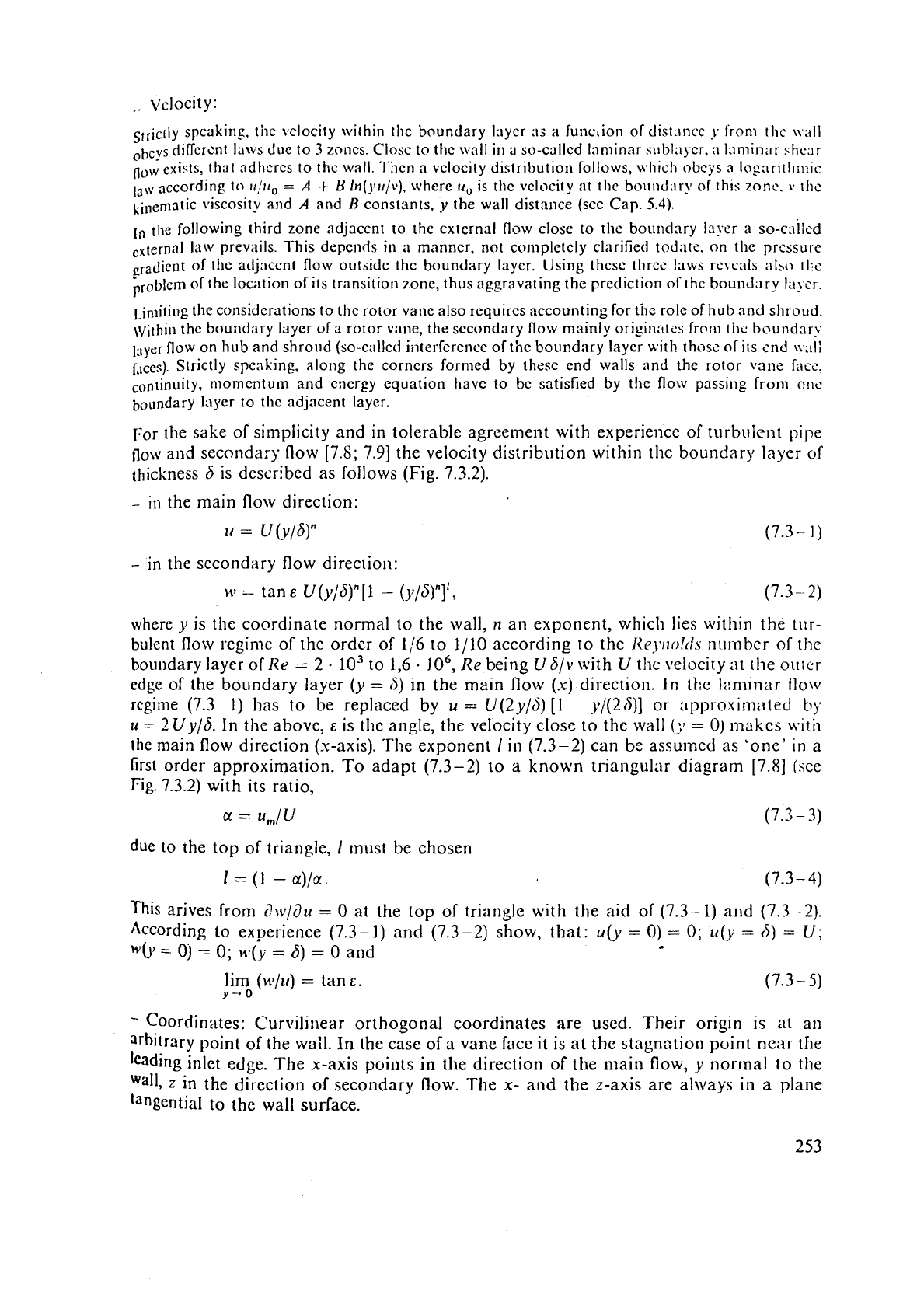
Slrlctl~
speaking. tile velocity within tlic boundary laycr
as
a
function of di~t~~ncc
j.
t'ronl the \\all
ot,cys difTcrcnt Irtivs due to
3
zoncs. Closc to thc \\,all in a so-callcd lnniinar sublajcr.
;i
laminar
shc3r
flow
exists, that ndhorcs to the wall. l'hcn a vclocity distribution follows, which obcgs a log;lrithn?ic
la,v
according to
ir.'ir,
=
A
+
B
In(yujv),
where
u,
is thc vclocity at the bound,rl-y of this zone.
v
the
viscosity
and
A
and
I3
constants,
y
the wall distance (see Cap.
5.4).
In
the following third zone ndjaccnt to the external flow close to tllc boundnry layer a so-cnllcd
,,ternal law prevails. This depcnds in
i1
manner. not completely cliirified tod;~tc. on thc prcssuie
gradient oi the adjaccnt flow outside thc boundary laycr. Using thcsc three lu\vs rc\cals alw thc
problem of the location of its transitiorl7.onc, thus aggravating the prediction of thc boundriry la!cr.
~inlitillg the
considerations
to the rotor vane also requircs accounting for the role of hub and shroud.
\v;rh~n the bou~ldary layer of
s
rotor vane, the sccondary
flow
mainly origin;ttes from thc: boundar!
I;lyer flow on hub and shroud (so-c;illcd interference of the boundary layer wit11 those of its end \;.I\;
f;~~cs). Strictly speaking, along the corners fornlcd by these end walls and thc rotor
vane
fi~ce.
continuity, momcntum and cncrgy equation havc to be satisfied by the flow passing from one
boundary layer to thc adjacent layer.
For the sake of silnplicity and in tolerable agreement with experience of turbulent
pipe
flow and secondary flow
[7.8; 7.91
the velocity distribution within the boundary layer
of
thickness
6
is described as follows (Fig.
7.3.2).
-
in the main flow direction
-
in the secondary flow direction:
M'
=
tan
E
U (y/b)"
[1
-
(y/6)"11,
(7.3
-
2)
where
y
is the coordinate normal to the wall,
n
an exponent, which lies within the tur-
bulent flow regime of the ordcr of
1/6
to
1/10
according to the
Xej.11olr1s
number
of
the
boundary layer
of
Re
=
2
-
lo3
to
1,6
-
lo6,
Re
being
US/v
with
U
the \lelocity at the orlter
edge of the boundary layer
(y
=
Oj
in the main flow
(x)
direction. In thc laminar flow
rcgime
(7.3-1)
has to be replaccd by
u
-
U(2y13)
[I
-
yj(2h)J
or :ipproximaled
by
u
=
2
Uy/6.
In the above,
E
is the angle, the velocity close to the wall
(:,!
=
0)
makes
~vith
the main flow direction (x-axis). The exponent
1
in
(7.3-2)
can be assulned
as
'one'
in
a
first order approximation. To adapt
(7.3-2)
to
a
known triangular diagram
(7.81
(sce
Fig.
7.3.2)
with its ratio,
o!
=
u,/U
(7.3
-
3)
due to ihe top of triangle,
1
must be chosen
This
arives from
i?\v/d~c
=
0
at the top of triangle with the aid of
(7.3-
1)
and
(7.3-2).
According to experience
(7.3-1)
and
(7.3-2)
show, that:
u(y
=
0)
=
0;
~l()l
=
6)
=
U;
W(-V
=
Oj
=
0; ~'(y
=
8)
=
0
and
lim
(\v/tr)
=
tan
E.
Y-0
-
Coordinates: Curvilinear orthogonal coordinates are used. Their origin is at an
3rbitrary point of the wail. In the case of
a
vane face it is at the stagnzition point
near
the
leading inlet edge. The x-axis points in the direction of the main flow,
);
normal to the
Wall,
z
in the direction of secondary flow. The x-
and
the z-axis are always in
a
plane
langential
to
the
wall
surface.
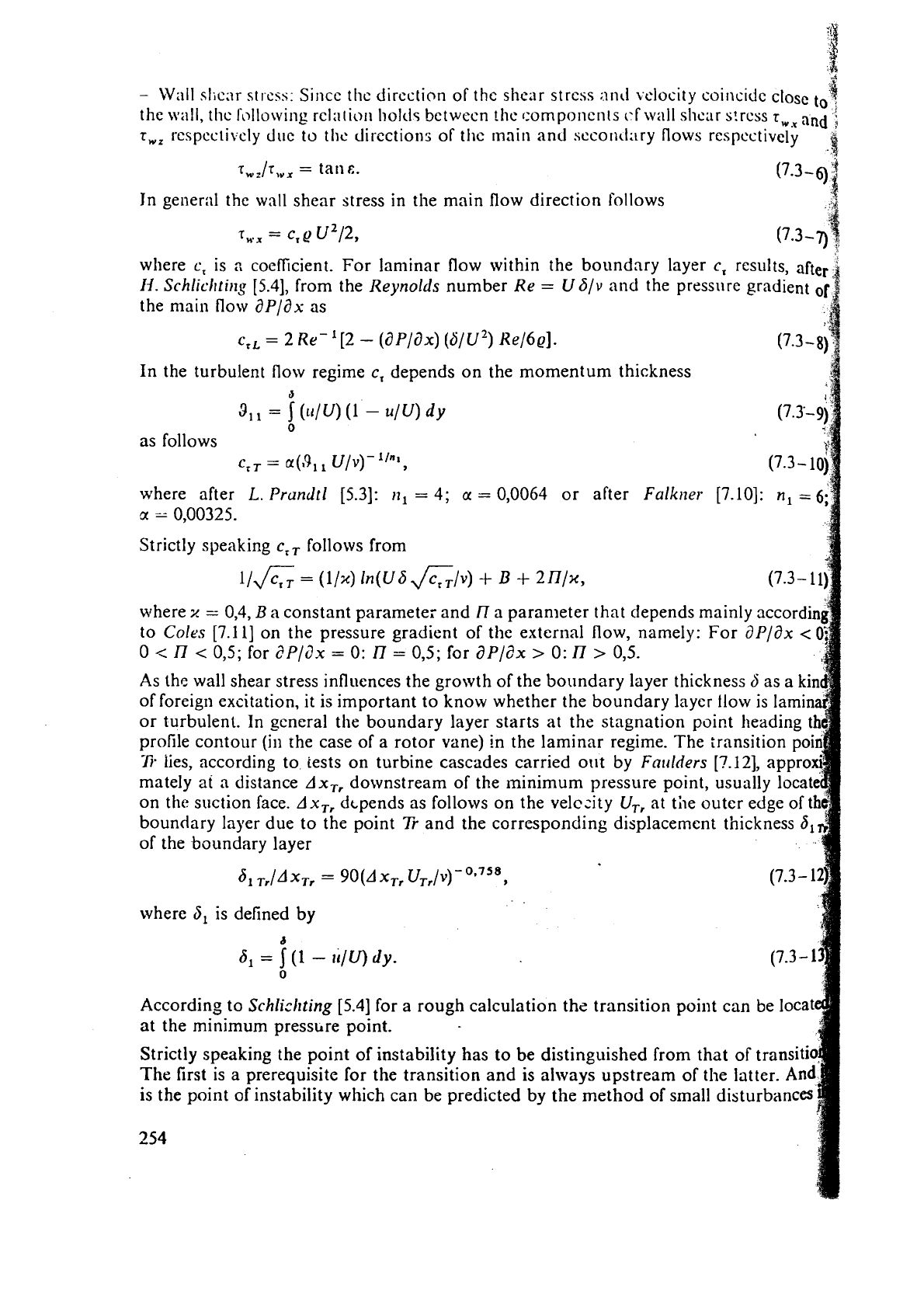
-
Wall slicnr
st
1.c~~: Sincc tlic dircction of thc shear st rcss :~nd
velocity
coirlcidc close
to
4
the wall, tlic rollowing rc1:ilioli holt!s bctwccn !hc r:omponcnls
(.f
wall shcar s!rcss
rWl
and
;
r,,
rcspcc~i~cly dilc to thc directions of tllc rnnin and sccon~lary flows respcctivcly
.!
Jn general thc wall shear stress in the main flow direction follows
Q
where
c,
is
2
coefficient. For laminar flow within the boundary layer
c,
results, after
'
11.
Schliclttiilg
[5.4], from the Reynolds number
Re
=
U
~Iv
and the pressllrc gradient
of
the main flow dP/ax as
c,,
=
2 Re-'[2
-
(aP/dx)
(S/U3)
He/6~].
(7.3-8fl
In the turbulent flow regime
c,
depends on the momentum thickness
J
311
=
5
(ll/U) (1
-
u/U)
dy
0
as follows
where after
L.
Prundtl [5.3]:
11,
=
4;
u
=
0,0064 or after
Falk~ter
[7.10]:
n,
=
6;
cx
=
0,00325.
Strictly speaking
c,,
follows from
I/&
=
(11%) ln(~6&/v)
+
B
+
21T/x,
where
x
=
0,4,
B
a
constant parameter and
I7
a paran~eter that depends mainly
;I
to
CoIes
[7.11] on the pressure gradient of the external flow, namely: For dP/ax
<
0
<
I7
<
0,5; for
dPlc7x
=
0:
I7
=
0,5; for aP/dx
>
0:
I7
>
0,5.
As thc wall shear stress influences the growth of the boundary layer thickness
S
of foreign excitation, it is important to know whether the boundary layer flow is lami
or turbulent. In general the boundary layer starts at the stagnation poir,t heading
profile contour
(ill
the case of a rotor vane) in the laminar regime. The transit
77
lies, according to tests on turbine cascades carried ollt by Fn~tlders [?.12],
mately at a distance Ax,, downstream of the minimum pressure point, usually locat
on the suction face. AxTr dtpends as follows on the velczity
U,,
at tile outer edge oft
boundary layer due to the point
Tr
and the corresponding displacement thickness
6,
of the boundary layer
61
xTr
=
90(A xTr U-~-,/V)-~"~~,
where
8,
is defined by
b
dl
=
(1
-
u/U)
dy.
0
According to
Schlicltting
[5.4] for a rough calculation the transition point can be locat
at the minimum pressclre point.
Strictly speaking the point of instability has to be distinguished from
that of t
The
first is a prerequisite for the transition and is always upstream of the lotte
is the point of instability which can be predicted by the method of srnall disturbances
254
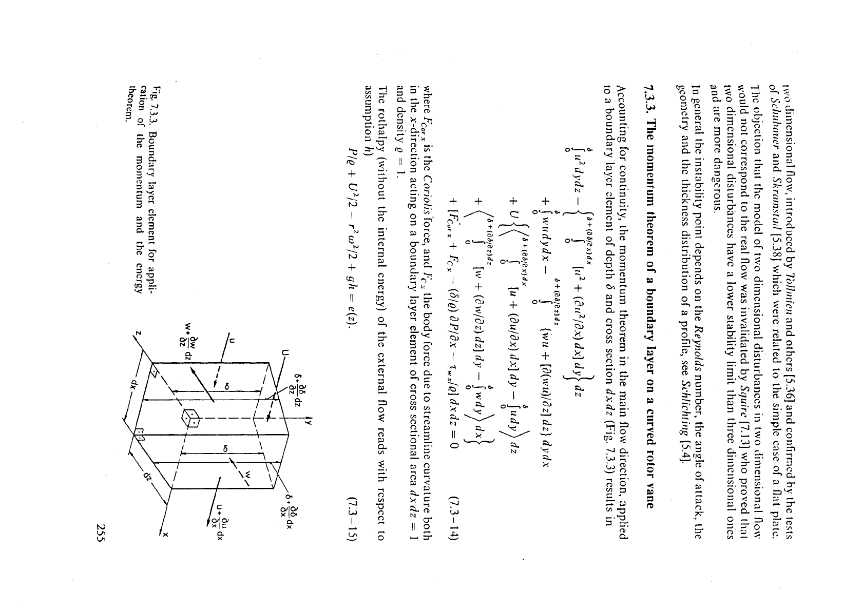
2x2
3
3%.
g22
2
0
--
8'2
B
1,
'EL2
7
av
5
-.
2Sc
c
a:
sz
3
;.
-
0
,JS
1
rCD
O
E3
52
g
32
0
3
2
g
a
zs
3
E
g
0
g
-.
3
=:
k?.
If<o
p;u=1
g.
=.
2
-3
-.
Ggg
6'
I
k.
0-e*
U
3
EL.
;+
a
k2-J
R
*
2
EL.
cl.
t-4
5
EL.
b1
w
a
'
e
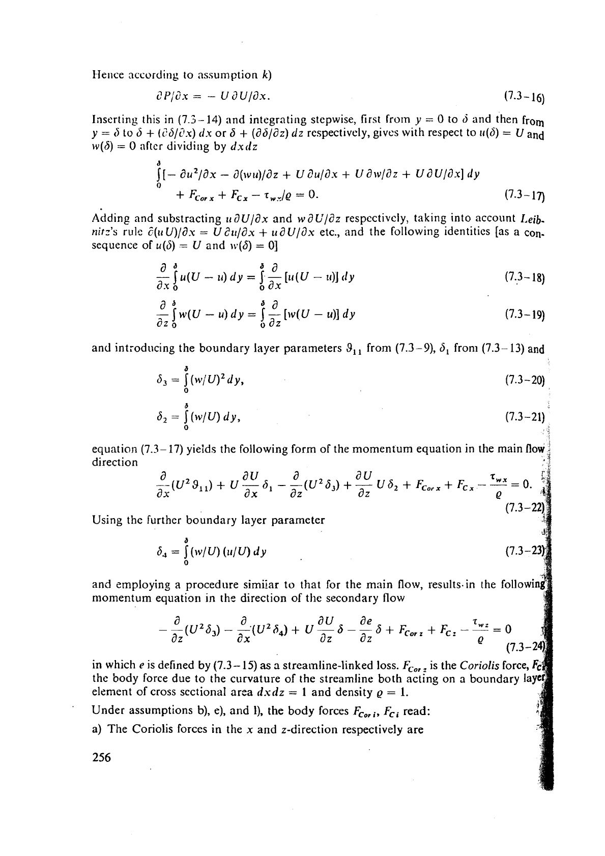
I-lelice according to assumption
k)
Inserting this
in
(7.3-14) and integrating stepwise, first from
y
=
O
to
6
and then
from
y
=
5
to
6
+
(?S/~.U)
rlx
or 6
+
(a6/dz)
dz
respectively, gives
with
respect to ~(6)
=
U
and
w(6)
=
O
after dividing by dxtlz
Adding and substracting
~~ilU/ax and watY/az respectively, taking into account
Leib-
nirz's
rule
t(~U)/d.u
=
U2tl/i?,u
+
trdU/dx etc., and the following identities [as a
con-
sequence of u(5)
=
U and ~(6)
=
01
a
*
da
-
u(U
-
11)
dy
=
f
-
[u(U
-
u)]
rly
ax
o
ax
and int;oducing the boundary layer parameters
8,
from (7.3-9), 5, from (7.3- 13)
and
equation (7.3- 17) yields the following form of the momentum equation in the main
flow
j
direction
.4
a
2
a
rr
a
au
--(U
9,
1)
+
U
-
6,
-
-(U2 6,)
+
-
U
6,
+
Fc0,,
+
Fc,
-
ax-
ax
az az
Using the further boundary layer parameter
and employing a procedure
similar to that for the main flow, resuIts-in the followin
nlomentum equation in the direction of the secondary flow
a a
au
ae
--(U263)--'(U264)+ U-6--6
+
Fcor,
+
Fc,-
az
ax
az
az
in which
e
is defined by (7.3-
15)
as
a
streamline-linked loss.
Fcor
is the
Coriolis
force,
the body force due to the curvature of the streamline both acting on a boundary la
element of cross sectional area
dsdz
=
1
and density
Q
=
1.
Under assumptions
b),
e), and
l),
the body forces
FCwi, Fci
read:
a) The Coriolis forces in the
x
and z-direction respectively are
256
