Raabe J. Hydro power - the design, use, and function of hydromechanical, hydraulic, and electrical еquipment
Подождите немного. Документ загружается.

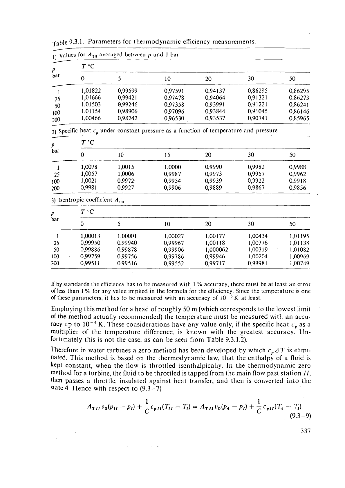
Table
9.3.1.
Parameters for thermodynamic efficiency measurxxnen ts.
/
Values for
A
,,,
nvcr;~ged betwccn
p
and
1
bar
/
P
T
"C
bar
0 5 10 20 30 50
2)
specific heat
c,
under
constant pressure as
a
function of temperature and pressllre
-
P
T
'C
bar
0 10 15 20 30 50
1
1,0078
1,0015 1,0000
0,9990
0,51982 0,9958
25
1,0057
1,0006 0,9987
0,9973 0,9957 0,9962
100
1,002
1
0,99?2. 0,9954
0,9939 0,9922
0,99
1
S
200
0,998
1
0,9327 0,9906
0,9889 0.9867
0,9S56
-
3)
Isentropic cocfficicnt
A,
,,
P
bar
If
by
standards
the
efficiency
has to be measured
with
1
%
accuracy, thcrc must be
at
least
an
crror
of
less than
1
%
for any value implied
in
the formula for the efliciency. Sincc the temperature
is
one
of
these parameters,
it
has to be measured
with
an accuracy of
K
at
Icast.
Employing this method for
a
head of roughly
50
nl (which corresponds to the lowest limit
of
the method actually recornmcnded) the temperature must be n~easured with an accu-
racy
up to
lo-'
K.
These considerations have any value only, if the specific heat
c,
as
a
multiplier of the temperature difference. is known with the greatest accuracy. Un-
fortunately this is not the case, as can be seen from Table 9.3.1.2).
Therefore in water turbines a zero
method has becn developed by which
c,
A
T
is elimi-
nated. This method is based on the thermodynamic law, that the enthalpy of a fluid is
kept constant, when the flow is throttled
iscnthalpically.
In
the thermodynamic zero
method for a turbine, the
fluid to be throttled is tapped from the main flow past station
11.
then
passes a throttle, insulated against heat transfer, and then is converted into the
state
4.
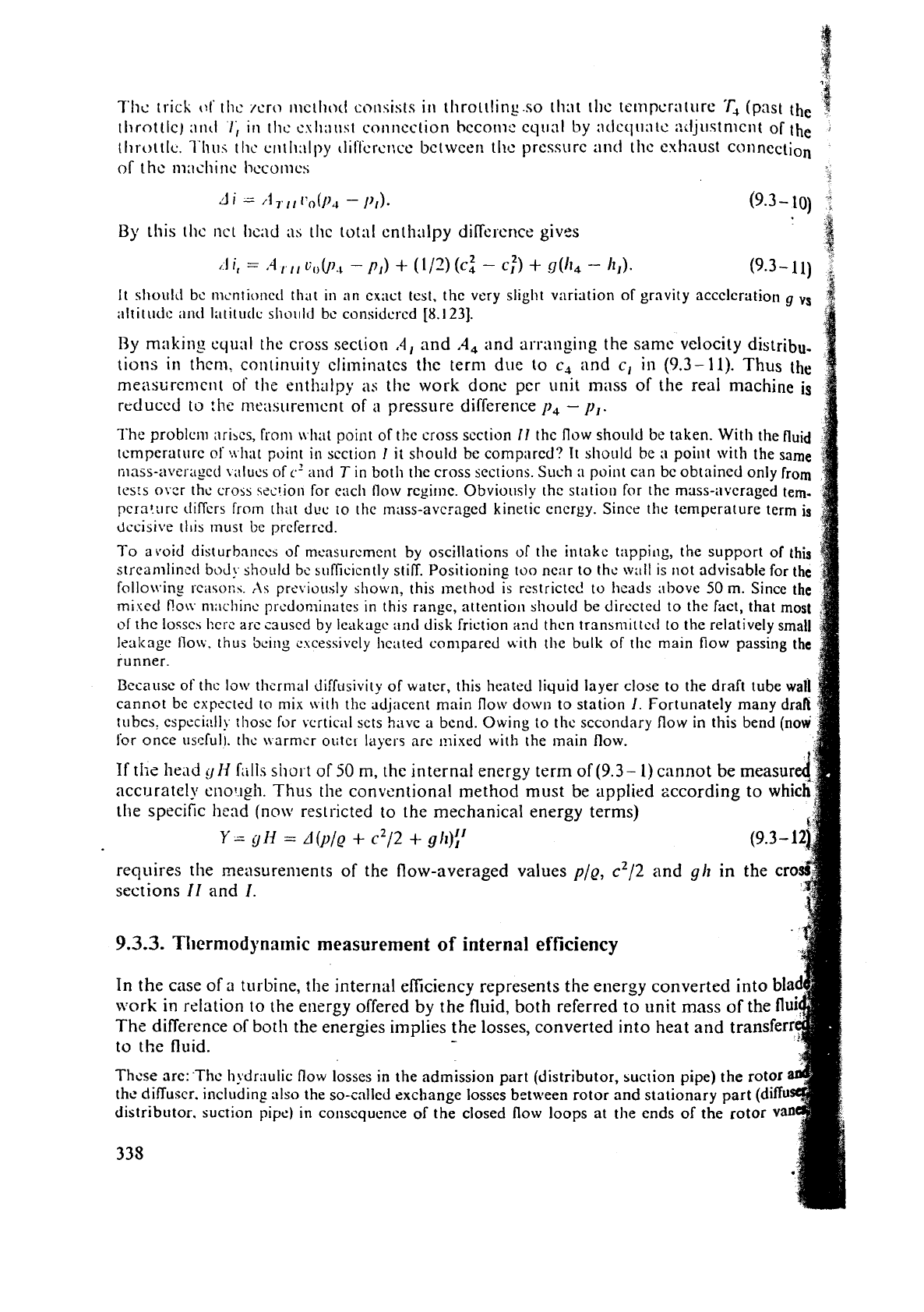
Hence with respect to
(9.3
-
7)
7'11~
trick
of
tllc
/cro
~iictllocf consists
ill
throttling.so
tli;it
tl~c te~npcraturc.
'r,
(past the
tllrottlc)
;irltl
1;
in
ilic
csIi;~~ist
~011ncc'tion hcco~lit' eq11;ll by adcqr~atc ;:~ljustn~cnt of
the
2
tllrottlc.
l'llu.;
thc
crl~Ii:llpy tliffcrct~cc bctwceri tl~c prcssurc
and
the
cxliaust COlincction
of
the machinc I~ccomc~
$
By
this tllc nct hcnd llic 1ot;ll cnthalpy diCfcscnce gives
It slioulJ bc nicntionetl that
in
an ex;lct tcst, the very slight variation of gravity acccleratioll
g
vs
;iltit~~dc ant1 latitutlv sllo111d be considcrcd
[8.123].
Ry
making
equril the cross section
'4,
and
.4,
and
arrailgirig the same velocity distrib",
tions in them, continuity eliminates the term due to
c,
and
c,
in (9.3-11). Thus
the
measurement of
the
enthalpy ;is the work done per unit mass of the real machine
is
reduced to
!he
nie:~sursn~ent of
a
pressure difference
p,
-
p,.
The problem arises, from ~vhat point of the cross scction
11
the flow should be taken. With the fluid
tcmpcrature oS:i.hat point
in
scction
1
it sliould be compared?
It
should be
a
point with the same
mass-averaged v;11ucs of
C
illld
T
in both the cross sections.
Such
3
point can be obtained only from
tests over rhc cross szc!ion for encli Flow regime. Obviously thc st:~tiou for the mass-averaged tern-
pcra!arc tiiffcrs frorn thilt duc to the muss-avcraged kinetic energy. Since the temperature term
is
decisive
tlris must be
preferred.
To avoid disturbnnccs of mcnsurcment by oscillations of tlie intake tappi~ig, the support of this
strcarnlinetl
bod!.
shoulci bc sufficiently stiff. Positioning too near to the wall is not advisable for the
follo\ving rci~soi:?;.
rls
previously shown, this lnethod is restricted to heads above
50
m. Since the
miscd Co\v ni;ichinc
predominates
in this range, attentiori should be directed to the fact, that most
OS
the losscs hcrc arc causcd by leakngu
anrl
disk friction and thcn transmitted to the relatively small
Icalcage llow, thus bcing cscessively hented compared with the bulk of tlie main flow passing the
runner.
Because of
thc low thcrrnal diffusivity of water, this heated liquid layer close to the draft tube
w
cannot be expected to mix
\vitll
the adjacent main flow down to station
I.
Fortunately many
d
tubes, especi;!lly thosc for vertical sets have a bend. Owing to thc sccondary flow in this bend (n
for once 11sl:ful). tlic \!.rtrmcr OlitcI layers arc mixed with the main flow.
If
tIi~
head
y
1-1
Lills
short of
50
m,
the
internal energy term of
(9.3-
1)
cannot be measur
accurately
eno!.lgh.
Thus
the conventional method must be applied zccording to
whi
the specific head
(now
restricted to the mechanical energy terms)
Y
=
yH
=
A(y/g
+
c2/2
+
ylz)il
requires the measurernents of the flow-averaged values
p/~,
c2/2 and
yh
in the
cro
sections
I1
and
I.
9.3.3.
Tl~ermodynamic
measurement
of
internal efficiency
In the case of
a
turbine, the internal efficiency represents the energy converted into
bla
work in relation to the energy offered by the fluid, both referred to unit mass of th
The difference of both the energies implies the losses, converted into heat and tran
to
tl:e fluid.
-
These
are:-The hydraulic flow losses in the admissio~i part (distributor, suction pipe) the rot
the
diffuser. including also the so-called exchange losses bet\veen rotor and stationary part
(d
distributor. suction pipe) in
consequence
of the closed flow loops
at
the ends of the rotor
v
335
51,rolld and huh c.spcci:illy ivhcrl \\lorking undcr off-dcsign conditions. Lastly
ii
comprises thc lossrs
of
d,,<~
fl-ictioll
and
Ica
k;lgr
(volunict ric loss) in thc rotor.
The
cncrgy offcrcd by the hcnd in the case of
a
turbinc corresponds to thc difirencc of
cnthalpy in an ideal nlncliine without these losses and without the lie;~t
flow
conr?ec?ed
l,crewith
A,,).
entropy
increment
'd.~'
is combined with
a
heat
dq
transferred irreversibly into the
fluid fro111 outside according to
ds
>
dq/T
(9.3-
13)
~t~i~tly speaking. this relation is valid
first
for a heat
flow
crossing thc system bounclnry of the
m3cliinc.
Now,
we
knon,
that the heat transfer through the walls of a hydraulic machine is negligibly
S,,,~I]. The heat, flowing into the fluid of a real machine, as
a
black box, from outside can
bc
inrcrprctcd as follows: First thc internal loss 3s an irrcvcrsible work is donc
by
kirtuc of viscous and
turb~lcncc-condirioncd stress undcr the strain ratc of thc fluid. This dissipation gcncrates hciit.
wllich can be considered 3s being afterwards
transferred
from outside into thc systcm (machine).
Col~trary to multistage thermal turbo engines, this heat revovery cannot be used in the following
~tages, as thcy usually don't exist in
a
water turbine.
~hus the real ~nachinc can be understood as a machine with heat flow from outside the
spstelll into
it.
Then tile entropy varies in the case of
a
real machine.
The
thcrmodynamic
relation for the increment of the enthalpy as a furlction of that of the entropy
ds
is given
by
[9.861
di
=
(d
ilds),
tls
+
(o7i/dp),
dp.
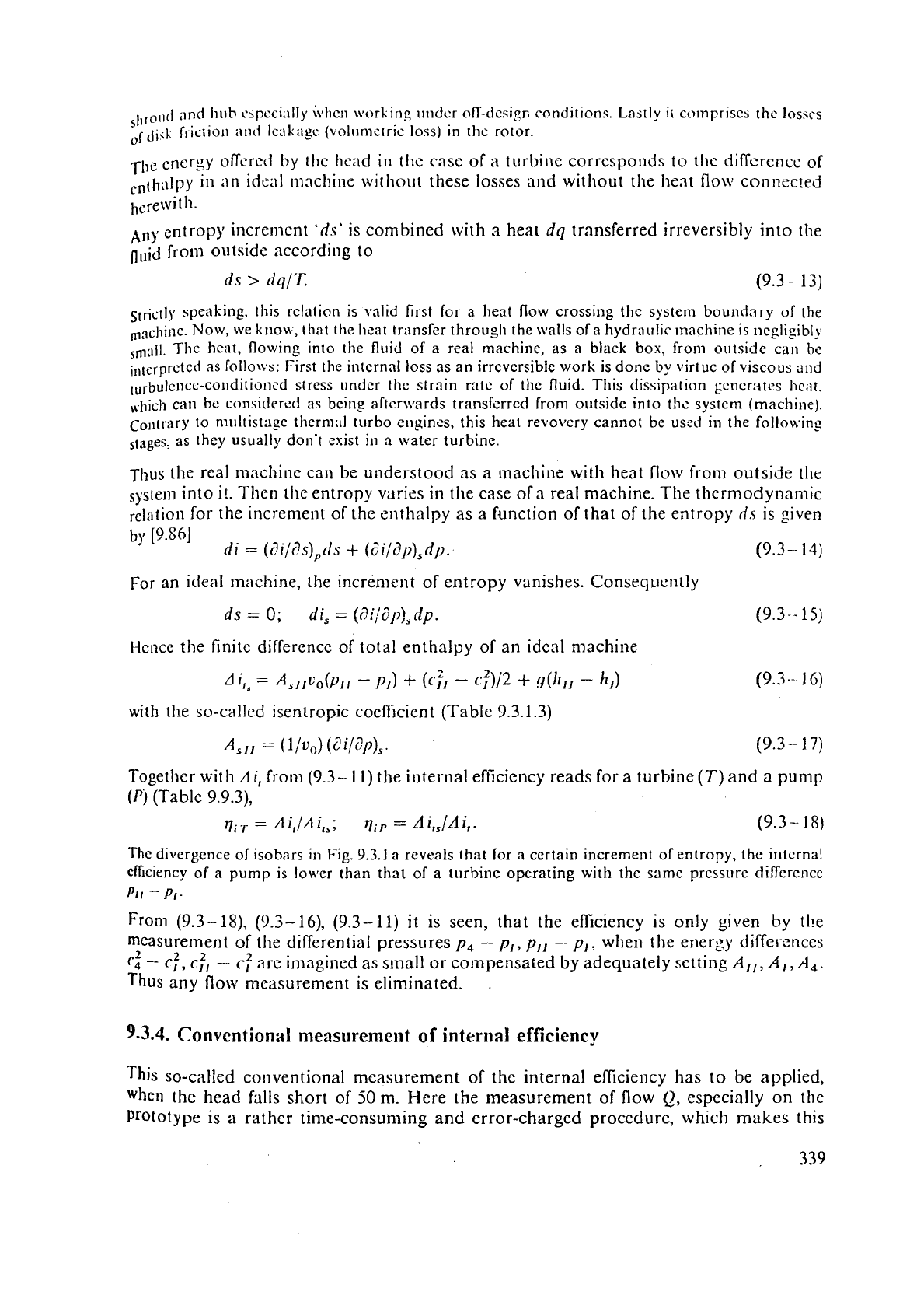
For an ideal machine, the increment of entropy vanishes. Consequently
Idcnce the finite difference of total enthalpy of an ideal machine
with
the so-called isentropic coefficient (Table 9.3.1.3)
A,,,
=
(l/n,)
cai/(?ll>,.
(9.3
--
1
7)
Togetller with
A
if
from (9.3- 11) the internal efficiency reads for
a
turbine
(T)
and a pump
(0
(Table 9.9.3),
1
=
AA;
qip
=
Aifs/Aif. (9.3-
18)
ll-ic di\lergence of isobars in
Fig.
9.3.1
a
reveals that
for
a certain increment of entropy, the intcrnal
cficiency
of
a pump is lower than that of
a
turbine operating with the same pressure difference
PI/
-
PI-
From (9.3-
i8),
(9.3-
16), (9.3-
11)
it is seen, that the efficiency is only given by the
measurement of
the differential pressures
p,
-
p,,
p,,
-
p,, when the energy diffel-ences
r:
-
r:,
rh
-
c.:
are imagined as small or compensated
by
adequately setting
A,,,
A,,
A,.
Thus any
flow
measurement
is
eliminated.
.
9.3.4.
Convcntion;rl
measuremeilt
of
internal
efficiency
This so-called conventional measurement of
the
internal efficiency has to be applied,
when
the head falls short of
50
m.
Here the measurement
of
flow
Q,
especially on the
Prototype is
a
rather time-consuming and error-charged procedure, which makes this
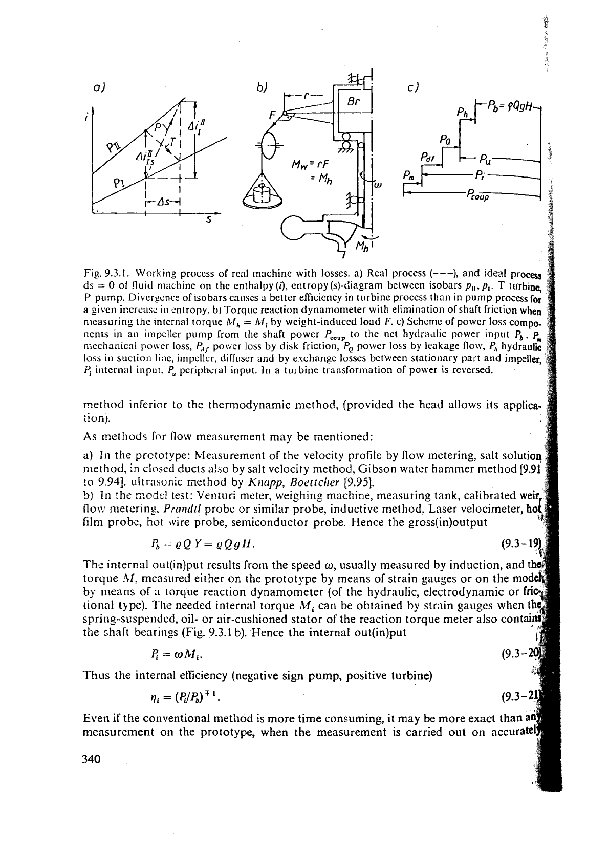
Fig.
9.3.1.
Working proccss of real machine with losscs.
a)
Real proccss
(---),
and ideal process
ds
=
0
of !luicl machine on thc enthalpy(i), entropy(.s)-diagram between isobars pl,,pl.
T
turbine,
P
pump. Diverscnc:: of isobars causcs
a
better efficiency in turbine proccss than in pump process
for
a givcn incrcasc
in
entropy.
b)
Torqi~e reaction dynamometer with elimination of shaft friction
when
nlcasuring the intcrnal torque
Ad,
=
Mi
by weight-induced load
F.
c) Schcme of power loss compo-
nents in an
inipcller pump from the shaft power
PC.,,
to the net hydradic
power
input
Pb.
Pm
n~echrtnicnl po\\er loss,
Pd,
power loss by disk friction,
Po
po\ilt.r loss by leakage flow,
c,
hydraulic
loss
in suction linc, impeller, diffuser and by exchange losses between stationary part and impeller,
intcrnal input,
P,
peripheral input. In
a
turbine transformation of power
is
rcvcrsed.
method infcrior to thc tllermodynamic method, (provided the head allows its applica-
tion~.
As
methods for flow measurement may be mentioned:
a)
In
the prctotype: bleasurement of the velocity profile by flow
metering,
srilt solution
method,
in
closed ducts alio by salt velocity method, Gibson watcr hammer method
[9.91
ro
9.94j.
ultrasonic met hod by Klrc~pp,
Boettclrcr
L9.951.
5)
In
the
modcl
test:
Venturi
metcr, weighi~lg machine, measuring tank, calibrated wei
flu\.:
metcrin~.
Prandtl
probe or similar probe, inductive method. Laser velocimeter,
h
film
probz, hot wire probe, semiconductor probe. Hence the gross(in)output
6
=
QQ
Y
=
~Qgtl.
The internal out(in)put results from the speed
w,
usually measured
by
induction, and
t
torque
?il.
measured either on the prototype
by
means of strain gauges or on the
m
by
means
of
a
torque reaction dynamometer (of the hydraulic, electrodynamic or
tional type).
TIie
needed internal torque
Mi
can be obtained by strain gauges
spring-suspended, oil- or air-cushioned stator of the reaction torque meter also
contai
the shalt bearings (Fig.
9.3.1
b). Hence the internal out(in)put
q
=
OM,.
Thus the internal csEciency (negative sign
pump,
positive turbine)
qi
=
(e/e)T1.
Even
if
the conventional method is more time consuming, it may be more exact than
a
measurement on the prototype, when the measurement is carried out on
a
340
In3
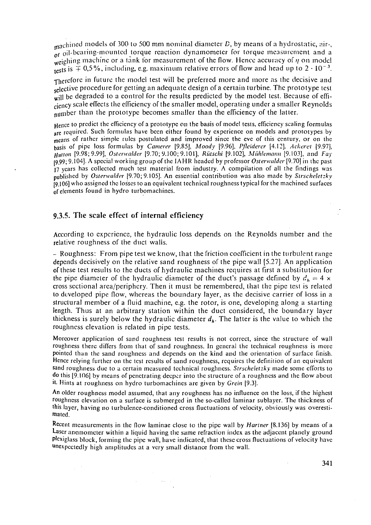
&ined niodelh of
300
to 500 mni nonlinal diameter
C,
by means of
a
hydrost:t;ic, ilir-.
or
oil-bca~~ing-r~~o~~~ltcri
torque reaction dynamometer for torque IneasuI.cnlent and a
,veigl~i~~g lnachine or a tink for measurement of the flow. Hcnce accurilcy of
rl
on
lnodel
is
T
0,5
%,
including, e.g. maximum relative errors
of
flow and head up to
2
.
10
3.
TherCfOrc in future the model test will be preferred more and Inore as the decisive and
selccti~e procedure for setting an adequate design of
a
certain turbine. The prototype test
Hr;l~
be degraded to a control for the results predicted by the model test. Because
of
effi-
ciency scale effects the efficiency of the
smaller model, opernting under a snialler Reynolds
than the prototype becomes smaller than the efficiency of the latter.
Hence to predict the efficiency of a prototype
on
the basis of
nod el
tests, efficiency scaling formulas
are
recluired. Such formillas have been eithcr found by experience on models and prototypes
by
means of rather simplc rules postulated and improved since the eve of this century, or on
the
basis of pipe loss formu1:is by
Can~er-or
[9.85],
Moorly
[9.96],
PJcidercr
[3.11-1.
~~Iirr-c~t
19.971,
~lrtrorl
[9.98; 9.991,
Ostrr\~alder
[9.70;
9.100;
9.1011,
Riitschi
[9.102],
.bJiihlrr~~nitr,
[9.103], and
Fa).
i9.99; 9.1041.
A
special working group of the
1AHII
headed by professor
Oster\t'~lldcr.
[9.70] in thc past
17
years has collected much test material from industry.
A
compilation of all the findings wss
by
Osr~r\tlnlder
[9.70; 9.1051. An essential contribt!tion was also made by
Srrschclerzkv
[g.106] \lfllo rlssipcd thc losses to an equivalellt technical roughness typical for the machined surraccs
of
elements found in hydro turbomachines.
9.3.5.
The scale effect of internal efficiency
According to experience, the hydraulic loss depends on the Reynolds number and the
relative roughness of the duct walls.
-
Roughness: From pipe test we know, that the friction cocficient in the turbulent range
depends decisively on the relative sand roughness of the pipe wall
[5.27].
An application
of these test results to the ducts of hydraulic machines requires at first
a
substitution for
the
pipe diameter of the hydraulic diamcter of the duct's passage defined by
dl,
=
3
x
cross sectional arealperiphcry. Then it must be remembered, that thc pipe test
is
related
to developed pipe flow, whereas the
boundary layer, as the decisive carrier of loss in a
structural member of a fluid machine,
e.g.
the rotor, is one, developing along a starting
length. Thus at an arbitrary station within the duct considered, the boundary layer
thickness is surely below the hydraulic diameter
d,.
The latter is the value to which the
roughness elevation is related in pipc tests.
Morcover application of sand roughness test results is not correct, since the structure of wall
roughness there differs from that of sand
roilghness. In gcneral the
technical
roughness is morc
pointcd than the sand roilghncss and depends on the kind and the orientation of surface finish.
Hence relying further on
thc test results of sand roughness, requires the definition of an equivalent
sand roughness due to
a
certain measured technical roughness.
Srrscheletzky
made some eflorts to
do this
[9.106]
by means of penetrating decpcr into thc structure of a roughness and the
flow
about
it. Hints at roughness on hydro turbomacl~ines are given by
Grein
19.31.
An
older roughness modcl assumed, that any roughness has no influence on the loss,
if
the highest
roughness
elevation on a surface is submerged in the so-called laminar sublayer. The thickness of
this layer, having no turbulence-conditioned cross fluctuations of velocity, ob~iously was overesti-
mated.
Recent measurements in
thc flow laminae closc to the
pipc
wall by
Hartner
[8.136] by means of a
Laser
iinernolncter within a liquid having the same refraction index as the adjaccnt planely ground
~lcxiglass block, formirlg thc pipe wall, have indicatcd, that thcsc cross fluctuations of velocity have
unexpectedly
high
amplitudes
at a very small distance from thc wall.
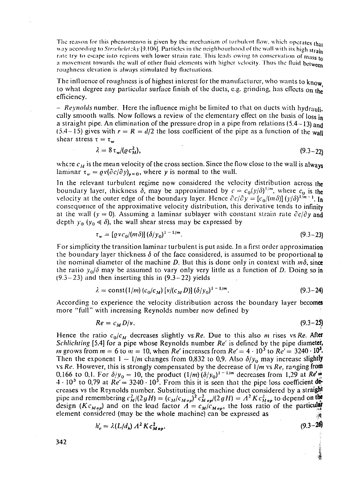
T:IIc
~C;\SOI~
for
this
ptieno~iic~io~i is
givcn
by
thc
rncch;inism
of
tl~rhulcnt
flo~v.
u.1iic.h
opcr;ltcs
thn,
l~i~y
:tccortlirig
to
S~r:;c./tc-l~~/:~.
['3.10(,].
Particles
in
thc
nciyhho\~rliood
of
thc
w;tll
with
its
hig],
strail,
riitc
try
to
esc;~pc
illto
rcyions
with
lower
str;~il~
ratc. .This Icacl:; o\vi~ig to cc~nscrv:itiori
of
nl,,,
,,
a
~nc>venlcrlt towards
thc
will1
of
othcr
fluid
clc~iicnts
with
higlicr
velocity.
'l.hus
th~
fluid
butwecn
roughness
clcvntion
is
illways s~imulated
by
Iluct\~;ltions.
Thc inlluencc of roughliess is of highest interest for the mnnuhcturcr, who wants to know
to what degree any particular surktcc finish of tl~c ducts, e.g. grinding, has cllccts on
th;
efficiency.
-
HeJl~o/tl,s number. Here the influence might be limited to that on ducts with hydrauli-
cally smooth walls. Now follows a review of the elementary effect on the basis of loss in
a straight pipe. An elimination of the pressure drop in
a
pipe from relations
(5.4-
13) and
(5.4.-
15)
gives with
r
=
R
=
(112 the loss cocfficient of the pipe as a function of the
wall
shear stress
r
=
s,,,
whcre c,,, is the mean velocity of the cross section. Since the
flow
close to the wall is always
laminar
r,,
=
~v(Gc/~3y),,,, where
y
is normal to the wall.
Jn the relevant turbulent regime now considered the velocity distribution across
the
boundary layer, rhickriess 6, may be approximated by
c
=
c0(y/6)""', whe~e c, is the
vsluci
ty
at
the outer edge of the boundary layer. Hcnce
SciZy
=
[c,:011(S)]
(y/S)""
'.
In
conscquellce of the approximative velocity distribution, this derivntlve tends to infinity
at
tne \vall
(y
=
0). Assuming a laminar sublayer with constant strain rate
c?cidy
and
depth yo (yo
<<
6),
the wall shear stress may be expressed by
For simplicity the transition laminar turbulent is put
asidc. In
a
first order approximation
the boundary layer thickness
b
of the face considered, is assumed
to
be proportional
to
the nominal diameter of the machine
D.
But this is done only in context with 1n6, sine
the ratio
yo/d
may be assumed to vary only very little as a function of
D.
Doing so
in
(9.3-23)
and then inserting this in (9.3-22) yields
According to experience
thc velocity distribution across thc boundary layer becomes
more
"f~ill" with increasing Reynolds number now defined by
Re
=
c,
Dlv.
(9.3
-
25)
Hence the ratio c,/c,, decreases slightly vsRe. Due to this also nl rises vsRe. After
Schliclltirrg
[5.4]
for a pipe whose Reynolds number Re' is defined by the pipe diameter,
,,,
?rows from
In
=
6 to
m
=
10,
when Re' increases from Re1=
4
-
lo3
to
Re1=
3240.10!
Then the exponent
1
-
l/m changes from 0,832 to 0,9. Also
6/y,
may increase slightly
vs
Re.
However, this is strongly competlsated by the decrease of I/nr vs
Re.
ra~ging from
0.166 to 0.1. For b!v,
=
10, the product (Ilm) (6/v,)'-'I" decrc3ses from 1,29 at
Re'a
1
-
lo3
to
0.79
at
Re'
=
3240
.
lo3.
From this it is seen that tllc pipe loss coefficient
ds
creases
vs
the Reynolds number. Substituting the machine duct considered by
a
strai$l
2 2
pipe and remembering cilj(Z
H)
=
(c,,~c,,,~,) c, d(2
gll)
=
A'
KC^,^^
to depend
on
the
design
KC,,^
and on the load factor
A
=
c,~/c,,,, the loss ratio of the
partied$
element considered (may
be
the whole machine) can be expressed
as
49
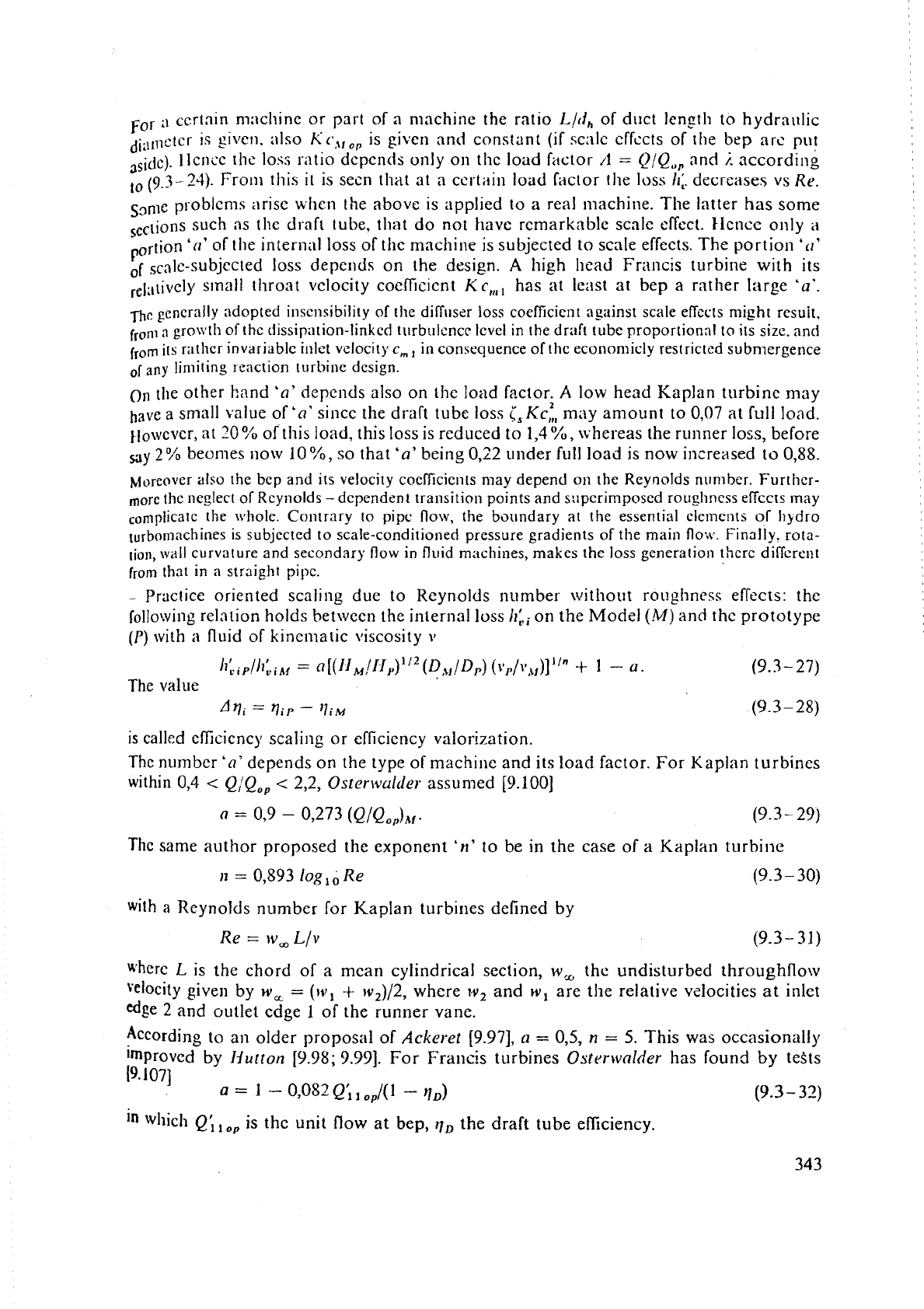
For
a
certain mncliine or part of
a
machine the ratio
Llrl,
of duct len_rlh to hydrai~lic
diilrnctCr is
~VCII.
;ilso
KC,,,^,,
is given and constant
(if
scnlc cffccts of tlie bep arc put
,,idc). llcncc [he loss ratio dcpcnds only on the load Fdctor
/1
=
QIQ,,
and
j.
according
to
(9.3-24).
Fro111 this
it
is secn that at a certiiin load factor the loss
11;.
decreases vs
Re.
S3nle psoblcn~s arise whcn the above is applied to a real machine. The latter has some
sections
such as the draft tube, tl~at do not have remarkable scale effect. IIence only
a
P
ortion
'(I'
of tlie internal loss of the machine is subjected to scale effects. The portion
'rl'
of
scnle-subjected loss deperlds on the design.
A
high head Francis turbine with its
relati~~ly s~nall throat vclocity coeflicient
Kc,,,,
has at least at bep a rather large
'u'.
fir:
generally
adopted insensibility of the diff~lser loss
coefficient
against scale effc'cts night resuit,
fronl
a
gro\\'th
of
thc dissipation-linked turbulcncc level
in
the
draft tube proportional to its size, and
from
its
ratlicr
invariable inlet velocity
c,,
in
consequence of thc econonlicly restricted submergence
of
any
limiting
loaction turbine design.
On
the other hand
'a'
depends also on the load factor.
A
low head Kaplan turbine may
ha\le a small value of
'n'
sincc the draft tube loss
[,KC,:,
may amount to 0'07 at full load.
However, at
20
O/o
of this load, this loss is rcduced to
1,4
%,
Lvhereas the runner loss, before
2%
beorlles now
10
%,
so that
'a'
being 0,22 under full load
is
now increased
to
O,88.
Moreover
also
the
bcp
and
its
velocity coefficients
may
depend on
the
Reynolds n~rmber.
Further-
more
the
neglect oTRcynolds
-
dependent transition points and s:lpcrimposed rouglincss effccts ]nay
c~mplicatc
the
whole. Contrary to
pipc
flow,
the
boundary at
the
essential ele~ncnts
of
Ilqdro
rurbornnchines
is
subjected
to
scale-conditioned pressure gradients of the
main
flo,~~. Finally. rota-
tion,
wall
curvature
and secondary flow
in
fluid machines, makes the loss generation
thcre
diffcreiit
from
that
in
a
straight
pipc.
-
Practice oriented scaling due to Reynolds number without roughness effects: the
rollowing relation holds between the internal loss on the Model
(M)
and
the prototype
(P)
with a fluid of kinematic \k.cosity
112
D
ti
=
a,'
(
,\f/Dp)
(vp/~,\~)]""
+
1
-
0.
(9.3
-
27)
The
value
'VI
=
ViI'
-
'li~
(9.3
-
28)
is
called cfficicncy scaling or eficicncy valorization.
The
number
'a'
depends on the type of machine and its load factor. For Kaplan turbines
within 0,4
<
Q,'Q,,
c
2,2,
Oster\vulcler
assumed [9.100]
0
=
09
-
0,273
(Q/Q,,),,.
(9.3
-
29)
The same author proposed the exponent
'n'
to be in the case of a Kaplan turbine
n
=
0,893
log,,
Re
(9.3
-
30)
with
a
Reynolds number for Kaplan turbines defined by
Re
=
bv,
Llv
where
L
is the chord of a mean cylindrical section,
\v,
the
undisturbed throughflow
velocity giver1 by
w,
=
(w,
+
1v,)/2, where
w,
and
w,
are the relative vzlocities
at
inlet
edge
2
and outlet edge
1
of the runner vane.
According to an older proposal of
Ackeret
[9.97],
a
=
0,5,
n
=
5.
This was occasionally
Improved by
Nutton
[9.98;
9.991.
For Francis turbines
Ostrrrvnlder
has found
by
teSts
[9.107]
a
=
1
-
0,082
Q',
,
.,/(I
-
rlD)
(9.3
-
32)
in
wllich
Q',
,
op
is thc unit flow at bep,
q,
the
draft tube efficiency.
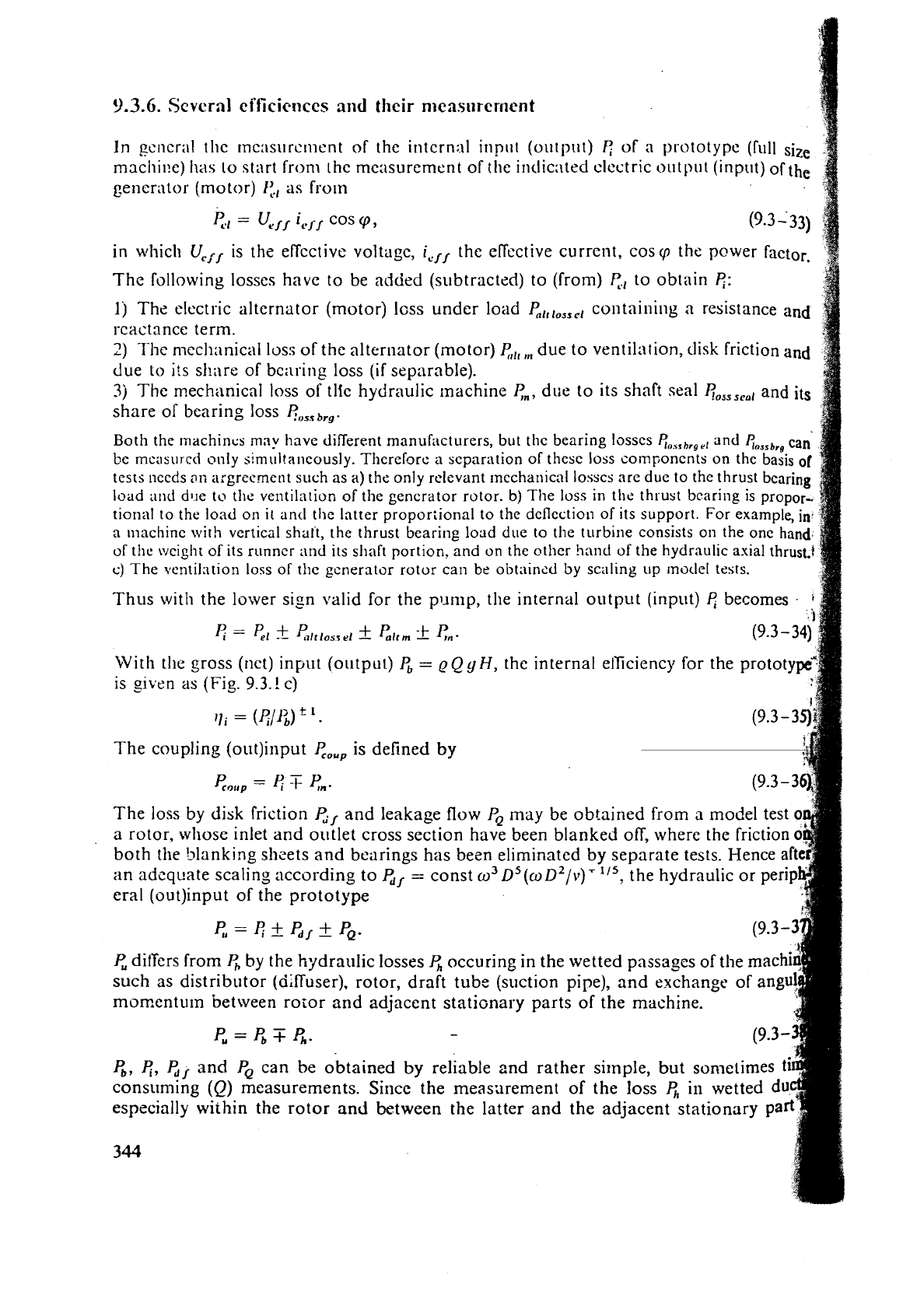
9.3.6.
Scvcrnl
ci'ficicnccs
and
their n~easorerncnt
In
gcncr;~l the ~ncasurc~nent of the intcrnnl inpt11 (output)
of a prototype (Tull size
machitx)
has
lo start from the measurement of the indicilted clcctric oulpl~t (inpr~t) of the
generator
(motor)
I:.,
as frutn
e.,
=
U,,.,
i,,.,
cos
9,
in which
UCjt,
is the effcctivt. voltage,
i,,,.
the effective current, cos
cp
the pewer factor.
The Tollowing losses have to be added (si~btractzd) to (from)
y,,
to obtain
e:
1
j
The electric alternator (motor) lcss under load
P,l,l,,,cl
containing a resistance and
reactance term.
2)
The mccl~:~nical
10s:;
of the alternator (motor)
e,,,
,,,
due to ventilation, disk friction and
due
to
its share of bciil-ing loss
(if
separable).
3j
The rnechi~nicnl loss of tlic hydraulic machine
en,
dlit. to its shaft seal
~,,,,,,,
and its
share or bearing loss
f?,,,,
$,,,.
Both the l~lachincs
ma!,
have different man
be
mcasured only simultalieously.
Thcref~re
tests i~ccds
21i
nrgreement such as a) the on
load
and
dtle
to the ventilntion of the gen
tional to the load on
it
and the latter propo
n
machine with vertical shalt, the thrust bearing load due to the tt~rbine consists 011 the onc
ban
of the
\\;eight
of its runncr
and
its shaft portion, and on the other hand of the hydraulic axial
thrus
c)
The vcntilation loss of thc
generator
rotor can
be
obtaincd by scaling up rnotlel tests.
Thus with the lower sig~l valid for the pump, the internal output (input)
becomes
E
=
P,I
+
Pl/tlosr
el
f
hrrn
*
en.
With lllc gross (nct) input (output.)
P,
=
qQ
yH,
the internal elTiciency for the prototy
is
given
as
(Fig.
9.3.!
c)
jji
=
(811;)
*
.
The coupling (out)input
P,,,,
is defined
p,",,,
=
4
T
8"
The loss by
disk
friction
G,
and leakage flow
PQ
may be obtained from
a
model test
a rotor, whose inlet and outlet cross section have been blanked off, where the friction
both the blanking sheets and bearings has been eliminated by separate tests. Hence
aft
;in adcquate scaling according to
4,.
=
const w3 D5(wD2/\~)T115, the hydraulic or perip
era1 (out)irlput of the prototype
p,=EfP,/+PQ.
P,
dif'fers from
P,
by
the hydraulic losses
P,
occuring in the wetted passages of the machi
such as distributor (diffuser), rotor, draft tube (suction pipe), and exchange of angu!
momentum between roior and adjacent stati~nary parts of the machine.
P.=P,TP,.
-
8,
c,
P,,
and
PQ
can be obtained
by
consuming
(Q)
measurements. Sirlcc t
especially within the rotor and
betwe
344
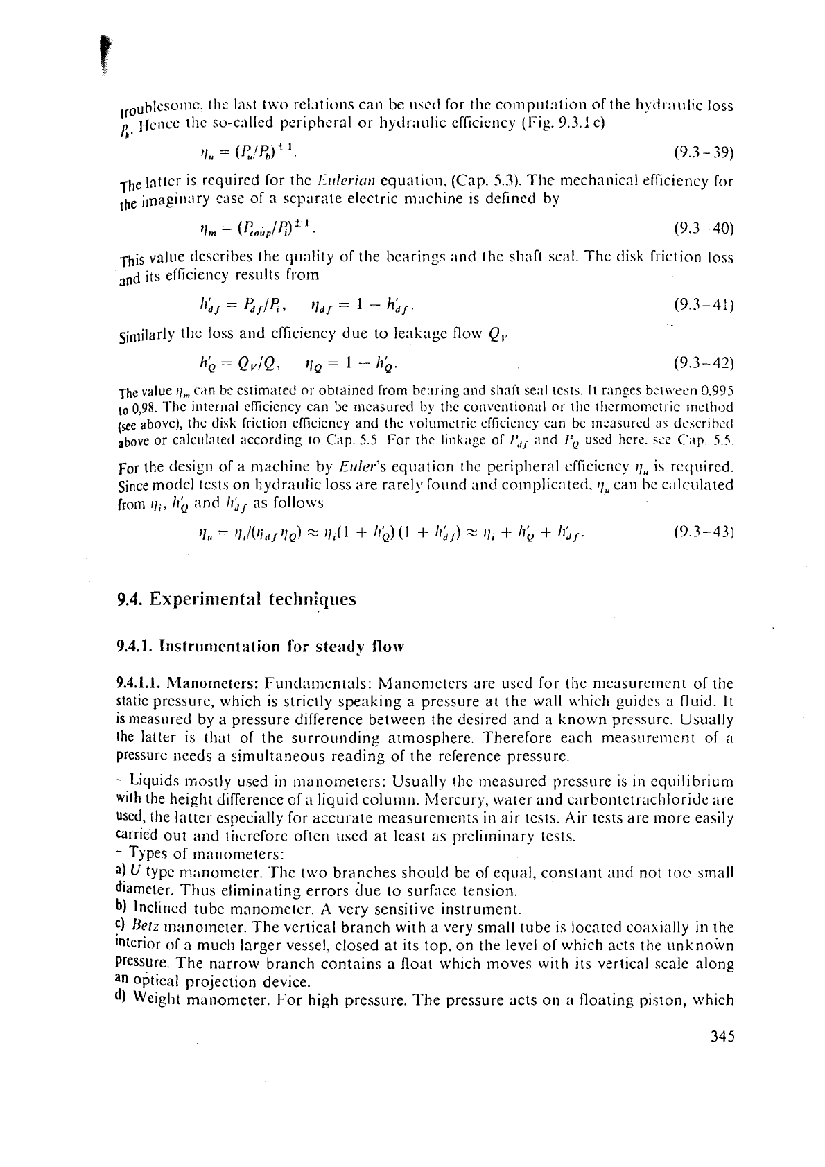
,roublcso~nc, thc
lilat
two re1;ltions can
Lx
urcd for the co~np~lt:ltion of the h~.dr;ll~li~ loss
Pr.
liencc the so-called pcriphcral or hytlraulic cfficicncy (Fig.
9.3.!
c)
,-hz
latter
is
rcqi~ircd for thc
Ilrrlcritrrr
equntic~~i, (Cap.
5.3).
Thc rnech;~nic;il efficiency f~r
,be
jmagi~1ilry cilse of
n
separate electric nwchine is defined
by
rhis value describes the qitality of the bcarings and the shaft seal. Thc disk friction loss
its efficiency results frorn
sinliIarly the loss and efficiency due to leakage flow
Q,,
The
valuc
I],,
can
be
estimated
or
obtained fro~n
he:^^
in& ai~d
shaft
se;il
1~5th.
It
ranges
b~t\vrcn
0,995
to
0,98.
l'hc
internal cfficicncy can
be
measured
by
the
conventional
or
tllc
rllcrmomcts~c ~ncihod
above),
the
di5k
friction cfficicncy and
the
volumc[ric
efficiency
can
be
~lleast~red
:I\
dcscribcd
above
or calcr~lated according
to
Cap.
5.5
For
the
linkage
of
P,,
and
FQ
uscd hcrc.
s:e
Cap
5.5
For the design of
a
machine
by
Elder's equatio~~ the peripheral efficicncy
11,
is rcqt~ired.
Since
lnodel tests on hydraulic loss are rarely round and co~nplicated,
rl,,
can be c,~lculated
[ram
ill,
Irb
and
II;,
as follows
9.4.
Experimental
techniques
9.4.1.
Instrumentation
for
steady
flow
9.4.1.1.
Rlanorncters: Funda~nentals: Manonlctcrs are uscd for the measurement of the
static pressure, which is
striclly speaking
a
pressure at the wall v.*hich guidcs a fluid.
It
is
measured by a pressure difference between the desired and
n
known pressure. Usually
the
latter is that of the surrounding atmosphere. Therefore each measurcnlcnt of
a
pressurc needs a simulta!~eous reading of the reference pressure.
-
Liquids ~nostly used in manometers: Usually the measurcd prcssurc is
in
eq~~ilibrium
with the height difference of
a
liquid colu~n~~. Mercury, \\later and carbontetrachloride are
used,
the latter especially for accurate measuren~ents in air tests. Air tests are Inore easily
carried
out and therefore often used at least as preliminary tests.
-
Types of manometers:
a)
U
type n7:tnolneter. .Phe t\vo branches should be
of
equal, constant and not toe small
diameter.
Thus eliminating errors due to surface tension.
b)
Inclined tubc manometer.
A
very sensitive instrument.
f)
Betz
manometer.
The
vertical branch with
a
very small tube is located co;~xially in the
interior of
a
much larger vessel, closed
at
its top,
on
the level of which acts the ilnknoivn
Pressure. The narrow branch contains
a
float which moves with its vertical scale along
an
optical projection device.
Weight manometer. For high pressore.
The
pressure acts
on
a
floating piston, which
i;;
nc;~rly frictionli::is.
Its
I;lscc is !,;~l;tiicctl by c;~libr;l.lctl ~vcights
on
the pistori. F-:linli~~~ti~,,
of
~rictioii
I>\
\il)r;~tt>~-x
~i~i~tio~i or rot;~tio~i of pist{)n.
C)
hl;~~ic~nictcr I;)r .ir~nt~lt;t~lcot~s nic;~~~rsc~~~cnL at
Iiliilly
st;~lions. Ilcre c;lcIl stiltion
is
conncciccl
I,:
i~
I~~C;I\LII-~II_C
ti1I~
\~ijl~
;I
I;trgc
VCSSC~
011
111~
~CVC~
of \vliicIi
~IC~S
the rcfcrellce
prcssu re.
-
('onvcrsion of prcss~~se illto
;it1
cIcctric sig1l:lt:
111
~c~lcr;~! this
voids
time loss
and
clinninutcs Iium;~n ohscrv;~tion crrors.
It
also l'i~cili~:~tes the
usc
of such an elcctric output
as
llle inpi~t of
;I
conlpi~lcr.
-
Type of co~~vcrsinn:
;I)
1'110~0
ccll:
.l'hc
c~.ll
is
lixcrl
on
:I
c;~rricr. whicll ~novcs
with
constant velocity from
a
point
of
ccrt;~in c.lcv;ltiol~
Joun
:iIo~ig
tlic
ni;~~ionictcr ti~bc. When
the
nicniscus of the liquid cc)lulnn
is
rc:~c.hc.ti. tl~c
lis!i~
Iicanl
c,rx:b~ing
lhu
ILI~C
is
\vc;~kcnctl by absorption bcfc~rc
rc;~ching
the photo
cell.
7-hc11 coun!i~lg
.;t;tl-tt;.
It
cntls
\vlicn
the
cirrricr p:~sscs
:I
Ycro mark of licigl~t
1c.vt.l.
17)
C;rp;~citor:
7'his
i.,
Iiscil
on
;I
niovi11y
c;~rricr-
simil;rr
10
;I).
!\t
thc
riiolr!cnt.
the
cylinrlricul capacitor
movcs
alnng
thc
iiquicl
colurii~~. ampliti~tlc or frcclucncy
of
;I
givcn clcctric;~l oscillation undergo
a
change.
cj
Resistor:
If
tlie m;lnolnctcr
licli~icl
is
;In
clcctric conductnr,
it
can be conncctcd to one pole ofa
b;lttcry. Thc otltcr
[~olc
is
con~lcctcd
via
n
straight
stiff
tIii11
?\.ire i~tt:iclicd to tlic tubc and dipping
in
thc
n~anoriictcr IiquiJ
at
its
oplxlsite
end.
The c!cc.tl.ic;\I rcsi~t;~ticc
of
tli~
non submcrgcd part
of
this
\virc
:lr~tl
thc
ci!rrc~~t
restilting hcrcol' ir:dic;~tc.;
1111'
Icn~lh
ol'
!hc n1:rnomctcr column.
dt
L)cform;~iion
bj
prcbburc: Thib c;t~l
Ilc
i~sccl
by
piciro clirartz cl-yst:ll or by
u
disk
with
n
micro strain
gallgc.
-
Problems involtrecl in nlzasusc~nent of pressure:
:II
I_)ampi~iy
nT
oscilliitio~ls.
A
narrow throat at the inlet of
the
n1:lnometer tube
may
be
lij~fl~l.
51
Guiding walls
\\.it11
non-stnllsti
flow
as
n
presecluisite for ;illy prcssure n:easurement:
S
lc;~siircment
oi
prcssiirc within
il
l7u~v ficltl recli~ises the usc of
a
mc:~suring probe so that
i?ow
sep;ira:ion is not caused ancl gcner.:~Ily so that
thc
rnain flow is tlisturbcd as little as
possible.
1-his is attained by ~nakir~g thc streamlined carrier ol'tlic pressure tappings small
i~r
comparison
\\.i;ll
the size of thc duct cvherc t!lc ~ncasurcmcnt is made. Furtllcrmore the
sur-hcc of this pr-ol?e ntxr the t:~ppinzs has to be ;is far
as
possible in tlie tangential
d~rcction
of
the
110~:
to be
measured.
,
3
,.
Si~ch
a
streamlined body contains usually four tappinss in its cylindrical port, distributd
u11ifol.rnly around the circumference of the probe. These four tappings asc interconnected.
This gives a cross section-averaged pressure
along the periphery, used for
measurement. To
n~ini~nize the size of tlie probe, these static pressure tappings are located
as near as possible
to
the curved axial symmetric head of the probe.
Due to
cur\;~ture of
the
strciimlines
in
this rcgion the static prcssure at the surfzce falls somewhat
short of its clcs~red
magnitude
in the undisturbed flow. This can be compensntcd either by a sufficient
d~rraocc
of
the
tappings from probe 1ie;id or b) thc artificial impact prcssure on the front facc ofad
:t\i.~lly
movable
rlns
(see Fig
9.4.1
c).
Thc correct position of rhc ring depends on the ~eynol
numbcr
of
tlic
flon
[9.72;
9.741.
-
Limits for the si7e of
the
probe and its tappings: The diameter of thc probe
can
reduced down to
5
rnm. This takes account of the capillarity effects of too small holes,
t
limitation of me;~surinp time and the limits of resistance i11 the tubes connecting
t
tappings wit11 tlie n~nnonieter.
A
prcssure port or tapping should be as small
as
possi
However with rcspcct to surface tension and pipe friction it should not be less
t
0.3
mln in di;~nictt.r.
\\'hen
the ports arc con~iecfed with micro semiconductor probes
t
diameter
of
the prbbe's head is limited by the actual smallest diameter of
2
mm
of
su
