Raabe J. Hydro power - the design, use, and function of hydromechanical, hydraulic, and electrical еquipment
Подождите немного. Документ загружается.

~i~
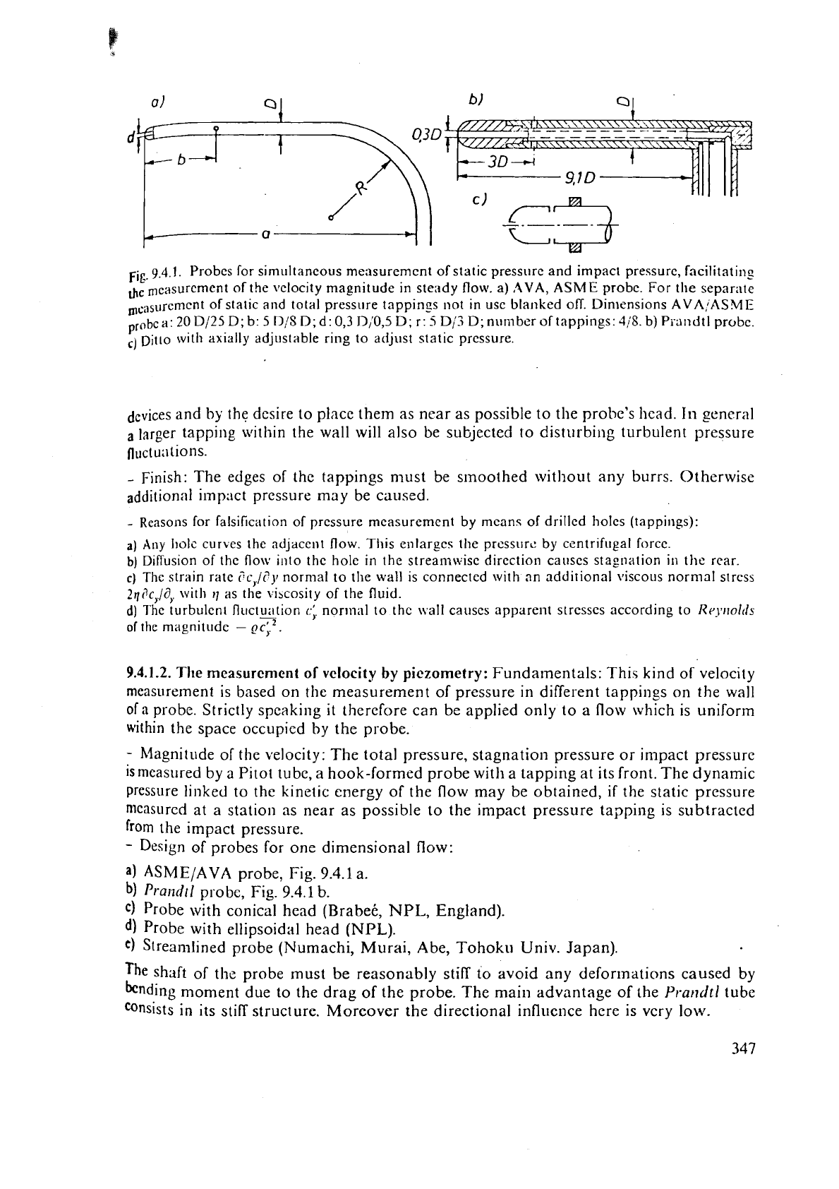
9.4.1.
Probes for similltancous measurcmcnt of static pressure and impact pressure, fncilitatin?
the
mcasurcment of the vclocity magnitude in steady flow.
a)
AVA,
ASME
probe. For the separate
In,,sl~rcmcnt of static and total pressure tappings not in usc blanked off. Dimensions
AVA,;ASME
P
'
*bc a:
20
Dl25
D;
b:
5
D!S
D;
d:
0,3 D/'0,5 D; r:
5
Dji
D;
nurilber of tappings:
4;s.
b) Pi-andtl probc.
,I
Ditto with axially adjustable ring to adjust static pressure.
dcvices and by the desire to place them as near as possible
to
the probe's head. In general
a
larger tapping within the wall will also be subjected to disturbing turbulent pressure
fluctu;1tions.
-
Finish: The edges of the tappings must be smoothed without any burrs. Otherwise
additional impact pressure may be caused.
-
Reasons for falsification of pressure measurement by means of drilled holcs (tappings):
a)
Any l~olc curbes the adjacent flow. Tliis enlarges the prcssurc by
centrifugal
f~rcc.
b)
Diffusion of thc flow illto the hole in the streamwisc direction causcs stagnation in
tho
rear.
C)
The strain rate
?c,/c'y
normal to the wall is connected with an additional viscous normal stress
Zrliic,/d,
with
11
as the vibcosity of the
fluid.
d)
The turbulent fli~ctuation
-
c;.
normal to the \\.all causcs apparent strcsscs according to
Rr~~noltls
of
the magnitude
-
Qc;.Z.
9.4.1.2.
The
mcasurcment of
vclocity
by
piczometry: Fundamentals: This kind of velocity
measurement is based on the measurement
of
pressure in different tappings on the wall
of
a
probe. Strictly speaking
it
therefore can be applied only to a flow which is uniform
within the space occupied by the probe.
-
Magnitude of the velocity: The total pressure, stagnation pressure or impact pressure
is
measured by a Pitot tube, a hook-formed probe with a tapping at its front. The dynamic
pressure
lil~ked to the kinetic energy of the flow may be obtained,
if
the static pressure
nlcasurcd at a station as near as possible to the impact pressure tapping is subtracted
from the impact pressure.
-
Design of probes for one dimensional flow:
a)
ASME/AVA
probe, Fig.
9.4.1
a.
b)
Prarzdtl
probe, Fig.
9.4.1
b.
c)
Probe with conical head (Brabet,
NPL,
England).
d)
Probe with ellipsoidal head
(NPL).
e)
Streamlined probe (Numachi, Murai, Abe, Tohoku Univ. Japan).
The
shaft of the probe must be reasonably still to avoid any defor~nations caused by
bending moment due to the drag of the probe. The main advantage of the
Prat~dtl
tube
consists in its stiff structure. Morcover
the
directional influence here is vcry low.
A
Rcynoltls ntinlb~r iiifltrcncc is given by its stern. For thc ASbIT: prohc any ilitcrfcrcnce bctwccn
;?robe hc;~tl .~nd stern bccoincb sn:ril!cst. Also thc Hoynolds ii~rmbcr infl\rcncc
is
ncgligiblc for
Ilighcr
nurnbcrs
[O.
IOS].
l'hc
probe with clli~soitlal hcad bch;tvcs si~nil~tr-ly ti) the
Prtrt~ilfl
tube althougl,
its
boundary 1;tyc.r may
bc
srn;~llcr
[9.108].
The conical probc c) givcs
;I
pru~lict;iblc stall at thu corncr
botwcc~l corlc ;rntl cylindcr. Duc
to
this
thc
st;~tic prcssurc nlc;~surcd on the cylindrical part,
becomes
more indcl>cndcnt of the llcynoltls numbcr than
in
the case
of
a
probe with
a
smooth trrtnsicnt
cur-vaturc from thc
head
to its cylindrical part.
-
Dircction:il sensitivity: The sensitivit)l of the
Pirot
tubc or the tapping at the front
of
the lube
is
liery small. For
a
flow deviating by
20"
from the axis of the tube, the impact
pressure (Icviates only by
I
%.
-
Intluence of
shear
flow: In the neighbourhood of walls or within a rotating channel
an
influence of shear flow exists. Such that the station of indicated velocity deviates from
the
tube axis.
-
Design of
flow
directional probes:
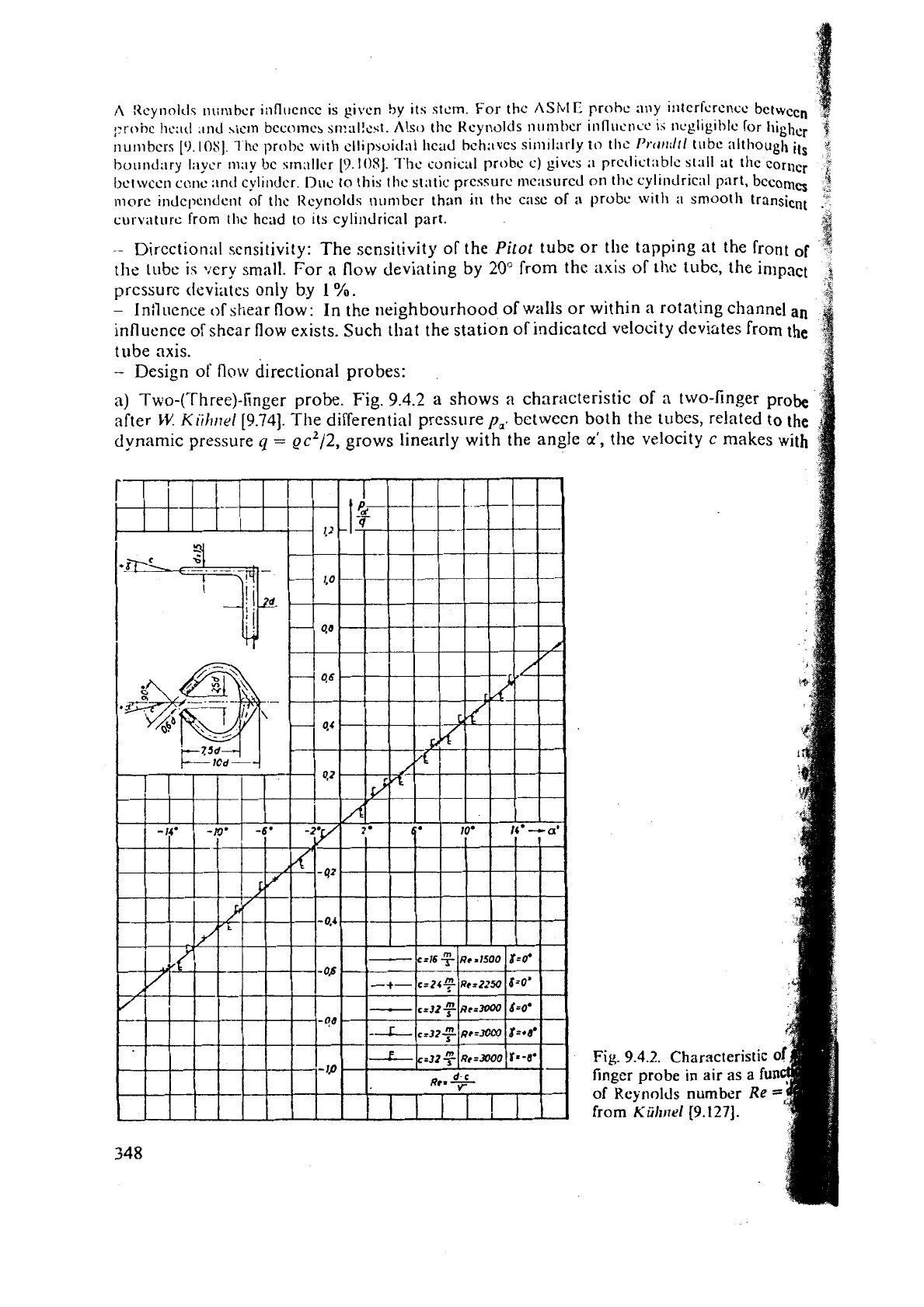
a) Two-(Three)-finger probe.
Fig.
9.4.2
a
shows
a
characteristic of a two-finger
probe
after
kt:
Kiilrrtel[9.74].
The differential pressure
p,.
between both the tubes, related to
the
dynamic pressure
q
=
gc2/2, grows linearly with the angle
a',
the velocity c makes
with
Fig.
9.4.2.
Characteristic
0
finger
probe in
air as
a
fu
of
Keyllolds
number
Re
from
Kiihilrl
(9.1271.
lhc
probe's axis.
It
is independent of the Reynolds numbcr. tt1hi.n the front f:~cc of c;~ch
lubc
is
pliincly
groulid
and pcrpcndicular to thc i~sis of the tubs.
The
Ineasuremcnt
is
also
jndepelldclit
of Illc pitoh
angle
p
in
u
range of
y
=
+
10". Here the magnitude
of
the
,,,locity
c
can
be
round by the dynamic prcssurc, when one of the tubes is turned
in
the
of
c.
In
tlie thrce-finger probe, this is cffccted
by
the tneiln tube.
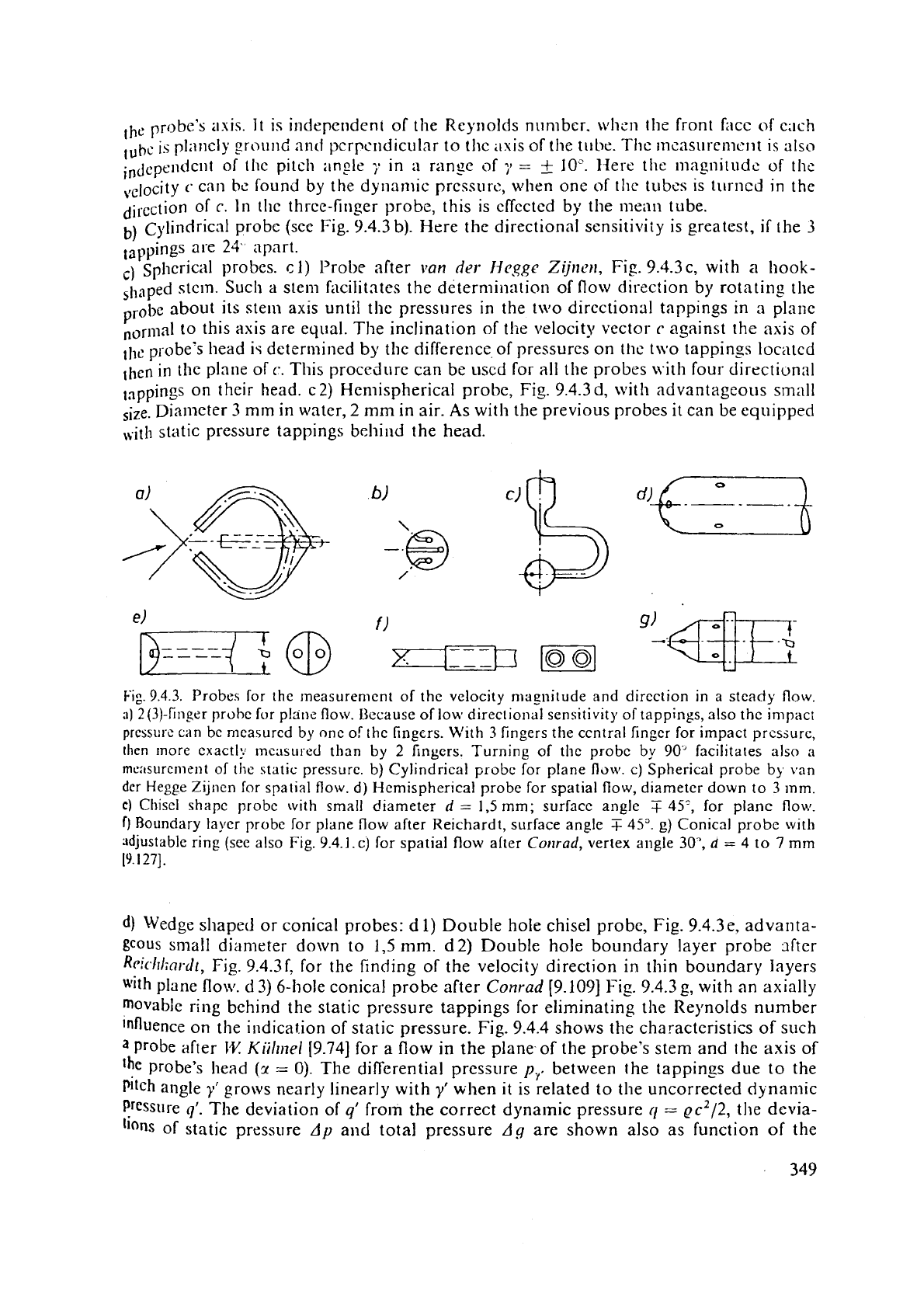
b)
~~lindricnl probe (see Fig. 9.4.3
b).
Here the directional scnsitir~iiy is greatest, if the
3
tappings
are
24.
apart.
c)
~~hcrical probes.
c
1)
Prol~e after
van
drr
Heggc
Zijllc711,
Fis.
9.4.3c, with
a
hook-
stun. Such
a
stem facilitates the determiilation of flow direction by rotating the
probe about its stell1 axis until the pressures in the two direction;ll tappings in a plane
nori~~al to this axis are equal. The inclination of the velocity vector
c
against the axis of
llle probe's head is determined by the difference of pressures on the t\vo tappin,.
09
located
then in the plane of
c.
This proced~~re can be used for a11 tile probes tvith four- dircctiunal
t3ppings on their head. c2) Hen~ispherical probe, Fig. 9.4.3d, with advantageous small
size. Diameter
3
mm
in water,
2
mm
in air. As with the previous probes
it
can be equipped
,,.ith static pressure tappings behind the head.
Fig.
9.4.3.
Probes for the ~neasurement of the velocity magnitude and direction
in
a
steady
flow.
a)
2(3)-finger prohc for plane flow. Bzcause of low directional sensitivity
of
tappings, also the impact
prcssurc can bc n~casurcd by onc of thc fingcrs. With
3
fingers tlie central fingcr for impact pressure,
then Inore exactly mcasurzd than by
2
fingers. Turning
of
the probc by
90'
facilitates also
a
meitsurcmrrit
of
the static pressure. b) Cylindrical probc
Tor
plane
fldw.
c) Spherical probe by van
dcr
Hegge
Zijnen for spatial flow.
d)
Hemispherical probe for spatial flow, diameter down
to
3 mm.
C)
Cliisel shapc probc with small diameter
d
=
1,5
mm;
surface angle
T
45',
for
planc flow.
f)
Boundary layer probe for plane flow after Reichardt, surface angle
T
45".
g)
Conical probc with
adjustable ring
(see also Fig.
9.4.1.
c)
for spatial flow alter
Corlrad,
vertex
angle 30',
d
=
4
to
7
mm
19.1271.
df
Wedge
shapetl or conical probes:
d
1)
Double hole chisel probe, Fig. 9.4.3e, advanta-
gcous
small diameter down to
1,5
mm.
d2) Double hole boundary layer probe dter
R~ichliar-dt,
Fig.
9.4.3f. for the finding of the velocity direction in thin boundary layers
with
plane flow.
d
3) 6-'hole conical probe after
Conrad
[9.109] Fig. 9.4.3g, with an axially
movabie ring behind the static pressure tappings for eliminating the Reynolds number
influence on the
indicat.ion of static pressure. Fig. 9.4.4 shows the characteristics of
such
a
probe after
IT
Kiilrnel
[9.74] for a flow in the plane of the probe's stem and the axis of
'he
probe's head
(1
=
0). The differential pressure
p,.
between the tappings due to the
pitch angle
y'
grows nearly linearly with
y'
when it is related to the uncorrected dynamic
pressure
9'.
The deviation of
q'
from the correct dynamic pressure
ri
=
ec2/2,
the devia-
'ions
of static pressure
Ap
and total pressure
Ag
are shown also as function
of
the
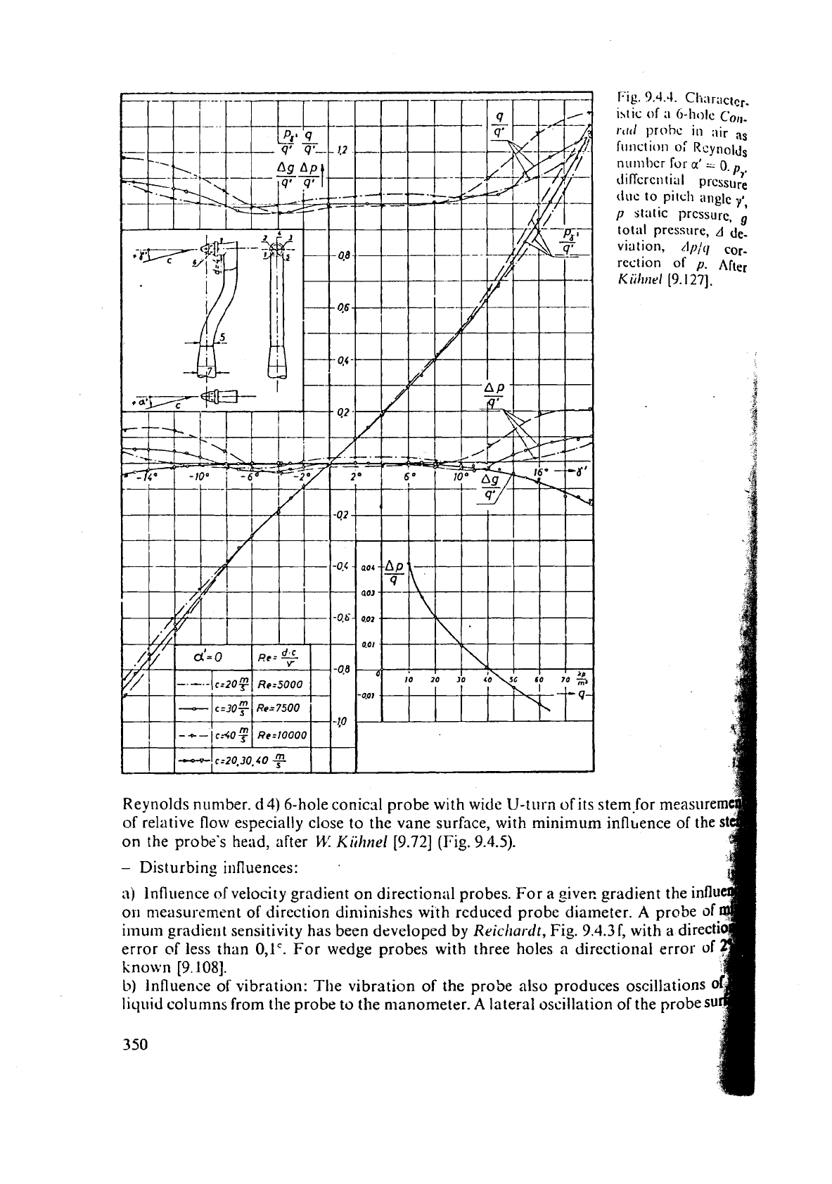
Fig.
3.4.4.
Cli,\ractcr-
13tic
of
;1
6-llolC
colt-
rt~il
prohc
in
;\ir
as
frlnction
o:
Rcynol,js
nu~nbcr for
a'
-
0.
P,.
iiiflcrcntial
pressure
due
to pitch
angle
yl,
p
st:ltic
pressure,
totill pressure,
A
de-
viation,
rlplq
cor-
rection
of
p.
~ft~.
Kiihnrl
[9.127].
1
4
B
i
Reynolds number. d4) 6-hole conical probe with
wide
U-turn of its stem-for measure
of relative flow especially close to the vane surface, with minimum
innhence of
the
s
on the probe's head, after
M.:
Kiihnel
[9.72]
(Fig.
9.4.5).
-
Disturbing influences:
;I)
Influence
of
velocity gradient on directional probes. For a giver. gradient the influ
011
measurement of direction diminishes with reduced probe diameter.
A
probe
of
ilnu~n
gradient sensitivity has been developed
by
Reichardt,
Fig.
9.4.3f,
with a direct1
error of less than
0,lC.
For wedge probes with three holes
a
directional error of
kno\vn
[9.108].
b)
Influence of vibration: The vibration of the probe also produces oscillstion~
liquid columns from the probe to the manometer.
A
lateral oscillation of the probes
350
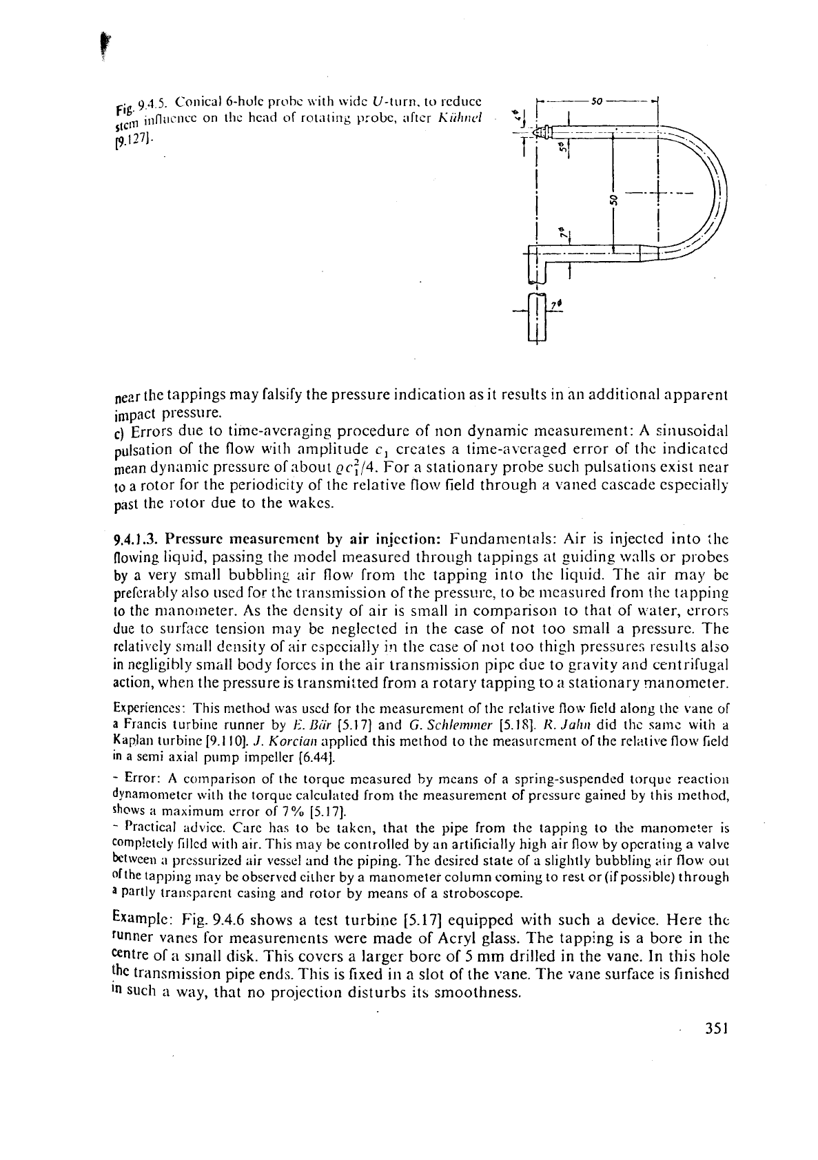
ig.
9.4.5.
Conical 6-hole probc with wide U-turn.
to
reduce
il,fl~lcncC on the head
of
rot;iting probc, after
Ci;l~tlcl
stein
p.1271.
near the tappings may falsify the pressure indication as it results in a11 additional apparent
impact pressure.
c)
Errors due to
time-averaging
procedure of non dynamic measure~nent: A sinusoidal
pulsation of the flow with amplitude
c,
creates
a
time-avcrased error of thc indicated
mean dynamic pressure of
:ibout
Qcf/4.
For
a
stationary probe such pulsations exist near
to
a
rotor for the periodicity of the relative flow field through
a
vanec! cascade especially
past the rotor due to the wakes.
9.4.1.3.
Pressurc measurcn~cnt
by
air
injection:
Fundamentals: Air is injected into ;he
flowing liquid, passing the model measured through tappings at guiding walls or probes
by
a
very small bubbling air flow from the tapping into the liquid. The air may be
preferably
also uscd for the transmission of the
pressure,
to be measured from thc tapping
lo
the n~anolneter. As the density of air is
small
in comparison to that of water, crrors
due
to surfacc tension may be neglected in the case of not too small a pressure. The
relati~fely small density of air
especially
ill
the case of not too thigh pressures results also
in
negligibly small body forces in the air transn~ission pipe due to gravity
and
centrifugal
action, when the pressure is transmitted from
a
rotary tapping to
a
stationary manometer.
Experienccs: This nlethod was uscd for the measurement of tlie rclative flow field along the vane of
a
Francis turbine runner
by
E.
Biir
[5.17] and
G.
Schl~mrner
[5.18].
I<.
Juhti
did ths samc with
a
Kaplan turbine [9.1 101.
J. Korciun
applicd this method to the meesurcment of the rel:!ti\le
flow
Leld
in
a
semi axial pump impeller [6.44].
-
Error:
A
comparison of the torque measured by means of
a
spring-suspended torque reaction
dynamometer with the
torquc calculated froni the measure~nent of pressure gained by this method,
shows
a
maximum error of 7O/" [5.17].
-
Practical advice. Care has to be taken, that the pipe from the tapping to tl~c manometer is
cornp!ctcly fillcd with air. This
may
be controlled by an artificially high air flow by operating
a
valve
bL.tween
a
pressurized air vessel and the piping. 7'hc dcsired state of
a
slightly bubbling air flow out
ofthe tapping lnny be observed eithcr by a manometer column comiilg to rest or
(if
possible) through
a
Partly transpnrcnt casing and rotor by means of a stroboscope.
Example:
Fig.
9.4.6
shows a test turbine
[5.17]
equipped with such
a
device. Here the
runner vanes for measuren~ents were made of Acryl glass. The tapping is
a
bore in the
antre of
a
s~nall disk. This covcrs
a
larger bore of
5
mm
drilled in the vane. In this hole
the
transnlission pipe ends. This is fixed in
a
slot of the vane. The
vane
surhce is finished
In
such
a
way, that no prqiection disturbs its smoothness.
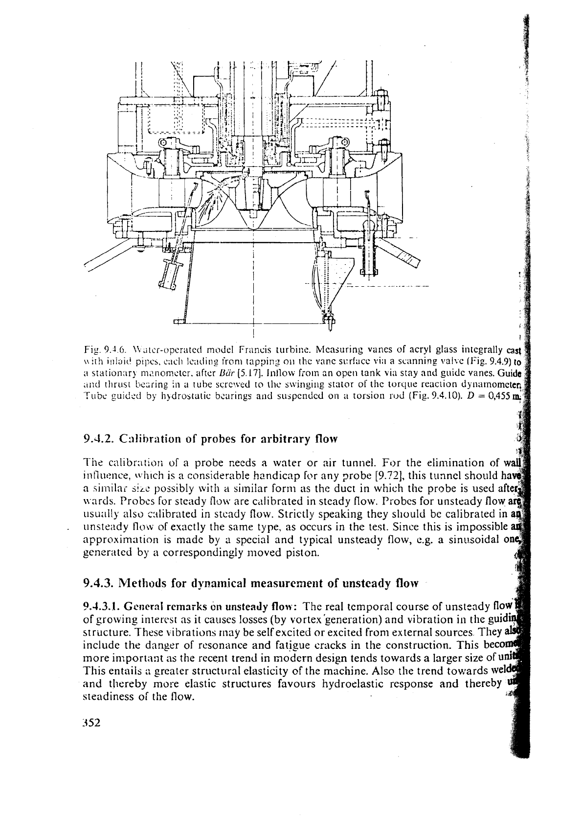
Fig.
9.1
6.
\\
d[cr-opcratcd
rnoJcl Francis
turbi~:c.
blcasuring vanes
of
acryl
glass
integrally
cast
\\:[!-I
i!~iaici
p~l:ch,
e;icl~ Icading
ircnl
tappirig
OII
thc vnnc
si:rfacc
\,ii~
a scanning
val~c
(Fig.
9.4.3)
to
n
stationar) m,?nom<tcr. after
Bur
[5
171.
Inllow
fio~fi
an
open
tank
via
stay
and
guide
vanes.
Guide
,ti:d
tl~rust
bczring
in
a
tube
scrcjved to
thc
stvingilig
stator of thc torque
reaciion
djnrilnorncteq
Tt~bc
suided
by
liqdro~ta~ic baring
al~d
suspcndcd
on
torsion sod
(Fig.
9.4.10).
D
=
0,4559
9.4.2.
C:ilibrntion
of
probes
for
arbitrary
flow
The
calibra:;ori
of
a probe ~eeds
a
water or air tunnel. For the elimination of
w
intlut:nce,
\\
h~ch
is
a considerable handicap
for
any probe
[9.?2],
this
tunnel should
a
sim~lai
S!L~
possibly
with
a
similar form as the duct in which the probe is used
nrds. Probcs for steady
flow
are c,ilibrated in steady flow. Probcs for unsteady
flow
t~sually also cslibrated
in
stcady
flow.
Strictly speaking they sliould be calibrated in
unsteady
flotv
of exactly the same type, as occurs in the test. Since this is impossible
approximrition is made by a special and typical urlsteady flow,
c.g.
a
sint~soidal
o
cener:ited by
a
correspondingly moved piston.
b
9.4.3.
Methods
for
dynamical
measurement
of
unsteady
flow
9.4.3.1.
Gcncrnl
remarks
on
unsteady
flou:
The real temporal course of unsteady
fl
of growing intercst as
it
causes losses (by vortex'generation) and vibration in the
gu
structure. These
1
ibrations rnay be selfexcited
or
excited from external sources
include the danger of
resonance
and
fatisue cracks in the construction. Thi
more in:porta:lt as the recent trend in modern design tends towards
a
larger size of
u
This entails
:;
greater structtirnl elasticity of the machine.
Also
the trend towards
we1
and thereby more elastic structures favours hydroelastic response
and
thereby
steadiness
of the Ilow.
352
3.2.
Vclocity
mcasurcrnenl:
Fundamentals: Contrary to the measurement
of
steady
9.4.-
sow,
in
an
unsteady flow otily tlic taagliitude or anc component of tlic vclocity can
bc
obt;,i~ied through direct measurement of one device, which uses tlirrmnl. optical or elnslic
emct~
of tlie flow with quick response. Morcover a simultaneoiis mcasurcment of illstan-
,a,leous pressure and velocity is not possible by these direct velocity mc;lsurcnients. l'hr
,,,,aslirement of the velocity vector needs a method such as the Laser anenlometry, \vhicIl
does not disturb tlie flow. Moreover it requires as many devices as velocity components
,,jst.
Principally the velocity vector now also can be measured by the simultaneous
rne,l-
,U,e~nent of instatitaneous pressure at difierent ports of one probe similar to the corre-
iponding vectorial probes for steady flow. Such probes are described under the scctio~i
measurenients'. They have a practical v;ilue only, if the gradient and the p-o~vth
r3t~
of the \relocity is small in the space, occupied by the probe. Further, the
interference
of
water hammer \\laves which are generated or reflected by the probe's stem, with the
probe itself does not allow an elimination of the influence of thc stem. At last the strictly
needed calibration of such a probe in real unsteady flow is rather troublesome.
-
Designs
of
different
probes:
,)
Probes using thcrtnal effects:
a3)
Hot wire probe:
It
uses the cooling effect of an electrically heated very thin wire which
is
exposed to the flow. Unfortunately this very sensitive device ca~i~~ot be used
in
liquids
with their strong impact stress and erosion.
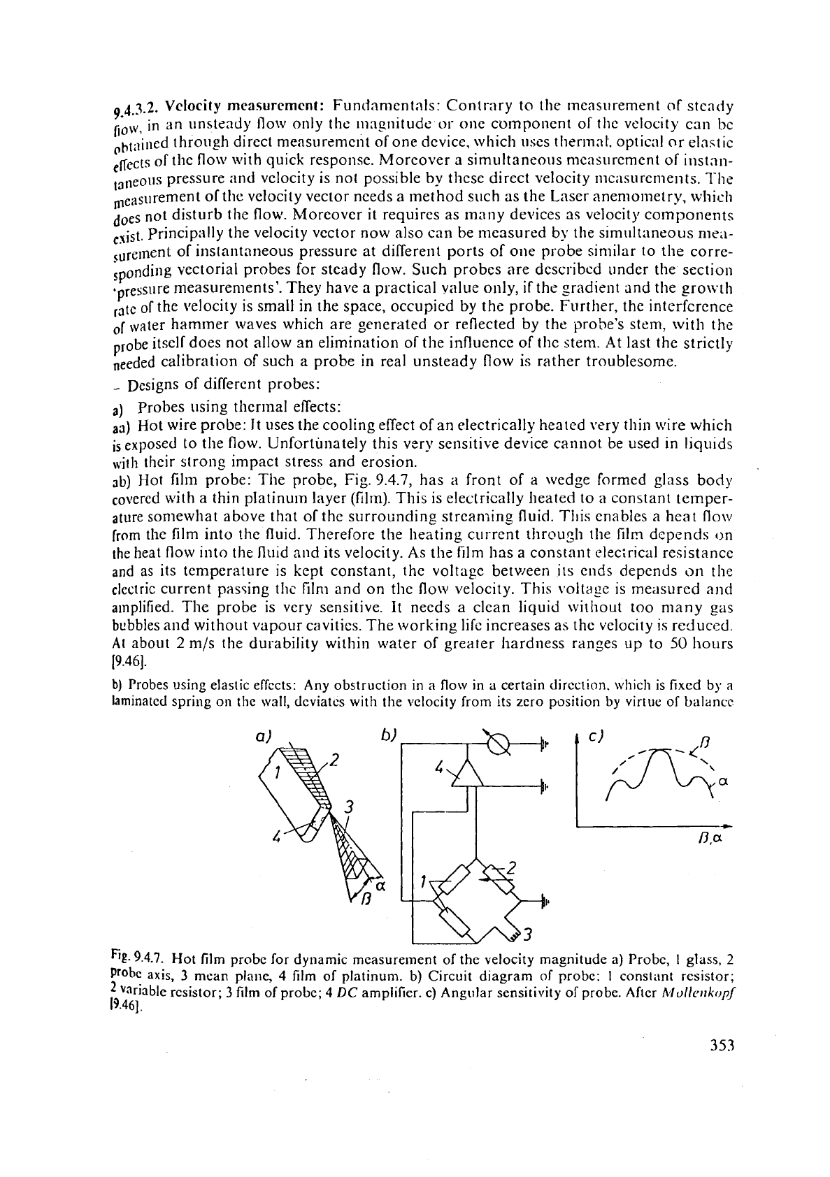
3b)
Hot film probe: The probe, Fig.
9.4.7,
has
a
front of
a
wedge formed glass body
with
a
thin platinum layer (film). This is electrically heated to
a
constant temper-
ature soniewliat above that of the
surroundin_g strcan~ins fluid. Tllis enables a heat flo\v
from
the
film into !he fluid. Theref~rc the heating current through the
film
depends
on
the heat flow into tlie fluid and its velocity.
As
thz film has a constant clecirical rcsistance
and
as its temperature is kept constant, the voltage between i~s ends depends
on
the
electric current
pas5ing the film and on tlic flow velocity. This voltase is measured
and
amplified. The probe is very sensitive. It needs
a
clean liquid without too many
gas
bubbles and without vapour cavities. The working life increases as the velocity is reduced.
At
about
2
m/s the durability within water of greater hardness ranges up to
50
hours
i9.461.
b)
Probes using elastic effccts:
Any
obstruction
in
a
flow
in
a
certain
direction.
which
is fixed
by
a
laminated spring on
the
wall, dcviates
with
the
velocity from its zero position
by
virtue of
balancc
5t-
9.4.7.
Hot film probe for dynamic measurement of the velocity magnitude
a)
Probe,
1
glass,
2
Prohe
axis,
3
mean
plane,
4
Iilm of platinum. b) Circuit diagram of probe:
1
constant resistor;
variable resistor;
3
film
of probe;
4
DC
amplifier.
c)
Angular sensitivity of probe.
Aftcr
Mollerrkopj
19.461.
betweell the dr;~g
and
cpring-born force on this obsttuction. This cIcvi:~tic~n car1 bc collvcrt
an
clcct~ic signal. Such all
instrument
can also indicate
;I
rcvcning os5il;11ing flow. 'The s
"flo~ pcntlulum" consists of
i~
disk of
1
rnln cli;~mctcr, subpcnclccl on
;I
la~nin~~tcd
sprtng
~hrou~h
;I
.;lot in the >trcan~lincd transducer, which is attilcll~d to the will1 bj
:I
hollow shaft.
end of the sprlng is clamped in the interior of this shaft. The mc;ln part of thc spring ca~rics
corc.
,It
rcst in the zero positiorl this corc is loci~tcd symrnctricnlly bctwcen two co~lc One
is the primary
the otl?er the sccond:\ry winding of
;I
transformer. 130th the coils are connecte
other, so that in thc zero position the voltnge bctween the ends of one of these coils is c
by that of
thc other coil.
If
the disk is shifted by the flow, the resulting voltage thcn induc
as signal for thc velocity, provided the probe's exciting frequency differs from its natural one.
c) Probes using optical effects: Here only Laser anemometers are mentioned:
ca) FOCUS method: Laser beams are focussed on
2
stations a known distance from each
other. The velocity is measured by the time interval a suspended particle needs to cover
this distance.
A
2-focus Laser was developed by
Eckai-dt
for
an
air compressor in
1976
and recently has been applied on a model Kaplan turbine in water by
Brnrirl
and
Se/bach
[9.63].
cb) Interference pattern method. Here a pattern of streaks parallel to each other and
wi
known distance from each other is generated by the interference of a
Laser
beam
wi
itself after its reflection and correspondirlg phase shift. The velocity component norm
to these fringes is measured by the time interval a particle needs to cover this know
distance [9.66], [8.136].
-
Problems arising with the Laser:
An
observation window is requircd with an out
surfacc normal to the beam. For internal flow in fluid machines a back-scatter
lnerlt is needed with its weakened light radiated back, whose signal strength
i
by
wall and window flare as reportcd by Brand and
Selbnch
[9.63]. Generally see
9.65;
9.671.
9.4.3.3.
Nleasurement
of
pressure:
Fundamentals: Similar to the measurement o
sure in steady flow the dynamic measurement of pressure in unsteady flow is restrict
only to that on walls.
A
streamlined carrier of the proper ?robe, as used in steady flo
experiences in unsteady flow a greatly varying angle of incidence.
This induccs an additional unsteadiness by starting vortices originating from the rear of the
and possibly also by stall. Mainly the
piezo electric effect or the elastic deformation of
loaded membrane of low inertia are used for conversion of unsteady instantaneous pressure
electric sisnal. Here the elastic deformation induces an unsteady displacement of the flow which
do
not exist originally.
-
Piezo quartz indicator: Such probes operate by the principle, that the surface o
quartz crystal is electrostatically charged
if
a pressure acts on it. Urifortunately the pro
is rather large. It has a favorably high resistance against erosion.
-
Membrane with strain gause: By application of adequate material and not too s
a size also such probes may be very highly resistant against corrosion and erosion.
the usual
sniall models the "Kulite type micro semi conductor probe" was deve
[9.811.
It
consists of a disk, which is 2,3 mm in diameter ar,d which is soldered to a
cylindrical box so as to be watertight. The interior of this box
is
exposed to a const
reference pressure. The strain of the disk due to its pressure-induced bendir;g is measu
by
a
semi conductor fixed on the surf~ce of the disk in the region of its largest strain
un
external pressure. This generates a voltage by change of resistance.
Unfortunately the probe often shows
a
drift of its
zero
point, which has
to
be countered by
repea
calibration. Moreover the probe is not very resistant against
a
cavitating flow.
3
54
9
4.4.
Problems
arising
with
rotating
probes
9,4.4.1.
General rcnlsrks about
rotating
probes: Calibration: For the ci~libration of a
rotati~lg probe it
secms
the best ihing is,
to
locate
it at the same station as it
will
be
used
Inter
on for taking measurements. In an air test this procedure
may
be donc
at
zero
discharge without the rotor. Secondary flow, caused
by
the stem
of
the probe as \yell
as
the
wakes of the stem must
be
kept off the head
of
the rotating probe, usually oriented
pcl.ipf~erall y.
Rotating Kulite probes may
be
calibrated by known air pressure conducted by
a
pipins
the rotor vane from
a
pressure vessel
at
rest.
-
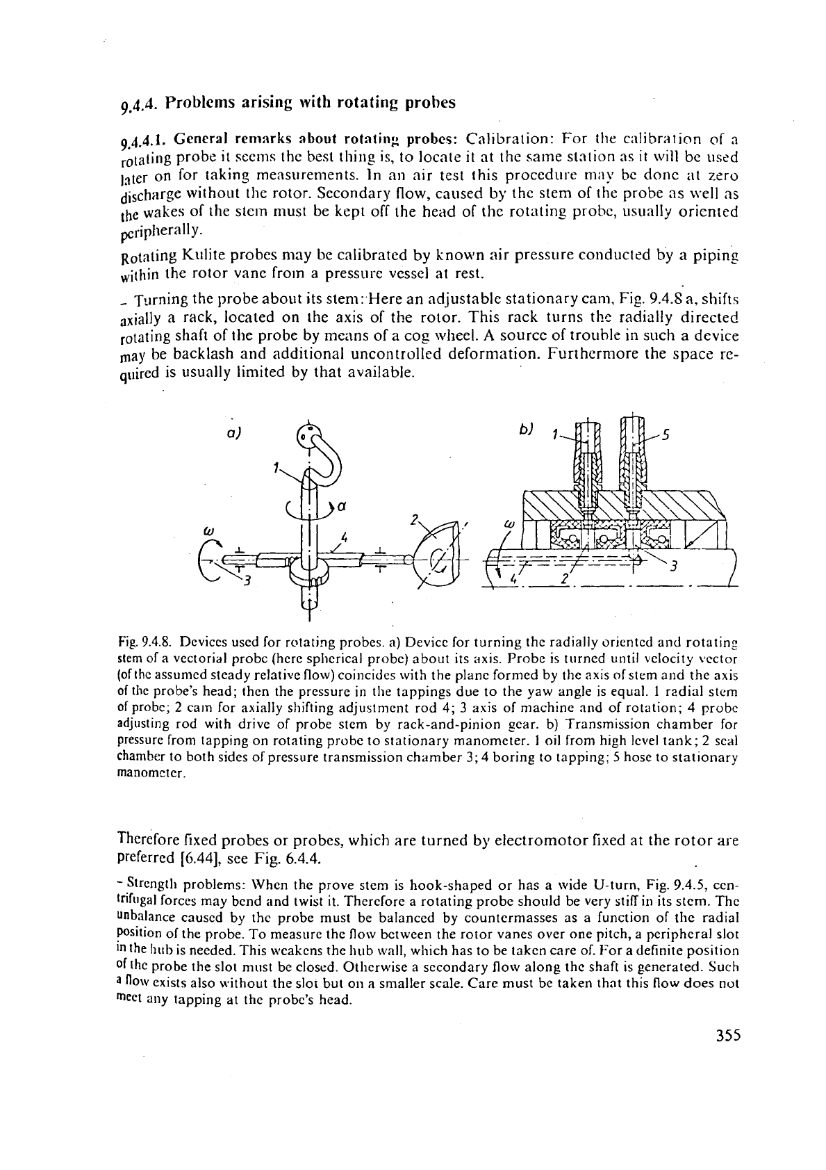
Turning the probe about its stem: Here
an
adjustable stationary cam.
Fig.
9.4.S
a.
shifts
axially
a
rack, located on the axis of the rotor. This rack turns
tl~r
radially directed
rotating shaft of the
probe
by means
of
a
cog
\\!heel.
A
source
of
trouble in such
a
device
ma)!
be
backlash and additional uncontrolled deformation. Furthermore the
space
re-
quired is
usunlly limited
by
that available.
Fig.
9.4.8.
Devices used for rotating probes.
a)
Device for turning the radially oriented
and
rotating
stem
of
a
vectorial probc (hcrc spherical probc) about its axis. Probe is turned until velocity vcctor
(of
the assumed steady relative flow) coincides with the plane formed by the axis
of
stern and the axis
of
the probe's head; then the pressure in the tappings due to the yaw angle is equal.
1
radial stem
of
probe;
2
cam for axially shifting adjustment rod
4;
3
axis of machine and of rotation;
4
probe
adjusting rod with drive of probe stem by rack-and-pinion scar.
b)
Transmission chamber for
pressure
from tapping on rotating probe to stationary manometer.
I
oil from high level tank;
2
seal
chamber to both sides of prcssure transmission chamber
3;
4
boring to tapping;
5
hose to stationary
manometer.
Therefore
fixed
probes
or
probes, which are turned by electromotor fixed at the rotor are
preferred
[6.44],
see
Fig.
6.4.4.
-
Strength problems: When the prove stem is hook-shaped or has
a
wide U-turn, Fig.
9.4.5,
ccn-
trifilgal forces may bcnd and twist
it.
Therefore
a rotating probe should be very stifiin its stem. The
unbalance caused by the probe must be balanced by countermasses as
a
function of
the
radial
psition of the probe. To measure the flow bctween the rotor vanes over one pitch, a peripheral slot
the
hub
is needed. This weakens the hub wall, which has to be taken care of. For a definite position
of
the
probe the slot must be closed. Otherwise a secondary flow along thc shafi is
generated.
Such
a
flow exists also without the slor but on
a
smaller scale. Care must be taken that this flow does not
meet ally tapping at the probe's head.
9.4.4.2.
Transmission
of values rne:~sured from rotor to stationary indicator
-
Rotating indicator: Hcrc the indicator, e.g rnanometcr, is fixed on the shaft, wllic
therefore has to be vertical. The indicated value may be received either by a rotati
camerr1 ur by
a
stationary camera with the aid
of
a rotoscope or a st\-oboscope, in whi
case the flon llas to bc steiidy. Disadvantage: Rotating
masses,
which must be balan
Advantage: No addition;ll torque of the transmission cievice. No transinission err
-
Rotating transmitter: Electric signals or other signals tr:lnsrormed into such signals
transmitted to
a
stationary receiver. Advantage: No frictional torque by trans111
device, no transmission error. Disadvantage: Expcnsivc, mcasured value must be tran
formed into electric signal.
-
Stationary indicator for electrically transmitted signals: Here the electrical measu
signals can be transmittzd by mercur:~ chambers. serking as sliding rings. Advant
Small friction. Disadvantage: Transmission error,
as
transmitted currents are rat
small
[9.8
11.
-
Optical transmission: Indirect by stationary camera and stroboscope or rotoscope
above or direct by Laser anernometry. Aclvantase: No tri=insmission error, no frictio
Disadvantage: Very expensive.
-
Stationary indicator with mechanical transmission: For the transmission of pressu
from a tapping on the rotor to a stationary ~aanometer (uszd as an indicator) a careful
sealed :-in$ chamber. Fig.
9.4.8
b, is required. This may bc tightened on both sides
radially elastic ring
elenlents gliding on a polished and cliromed sleeve around the sh
>!oreover this may be tightened by ring chambers, filled with pressurized oil on bot
sides. The oil pressure hitherto has to be al?ove the pressure transmitted and is produce
by
an oil vessel located above the oil chamber. It must operate beforo the shaft star
rot~lting
[9.:27].
Advantage: No transmission error. Disadvantage: Frictioilal torque.
9.4.4.3.
Scanning
valve
for
conncction
of
rotating
tappirlgs
wiih
statiocary mtloomete
Fundarn~ntals: Usually many rotating measuring tappings have to be connected
t
szveritl available stationary manometers. In the case considered of a steadily operatin
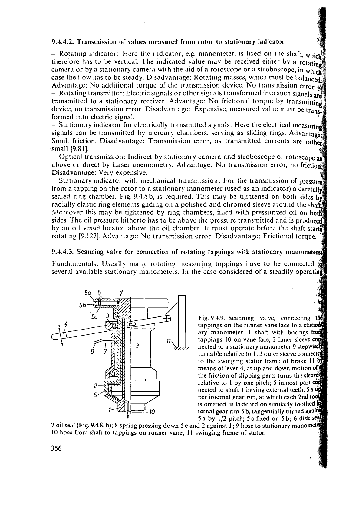
Fig.
9
3.9.
Scanning valve, con~ecting
tappings on thc runner vane
face
to
3
stati
ary inanometcr.
1
shaft \vith borings
tappings
10
on vane fdce,
2
inner sleeve
nccted
to
a siationary nallorneter
9
stepwl
turniible rz!ative to
1
;
3
outer sleeve connec
to
the swinging stator frame of brake
If
means of
lever
4.
at
up
and
do\\lu
motion
0
the friction of slipping parts turns
the
sle
relative to
1
by
one
pitch;
5
inmost part
nected to shaft
1
having external teeth.
5
per internal gear
rim,
at which each
2nd
to
is
omitted,
is
fastened
on simila~Iy toothed
tcrnal gear
rim
5
b, tangentially turned ag
'
5a
by
1,'2
pitch; 5c fixed on
5
b;
6
disk
7
oil se;il
(Fig.
9.4.8.
b);
8
spring pressing down
5
c
and
2
against
1;
9
hose to stationary manom
10
ho~e from shaft to tappings on runner
bane;
11
swinging frame of stator.
356
