Raabe J. Hydro power - the design, use, and function of hydromechanical, hydraulic, and electrical еquipment
Подождите немного. Документ загружается.

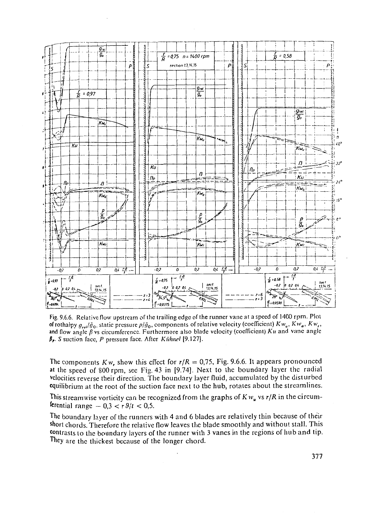
Fig.
9.6.6.
Relative
flow
upstream of the trailing edge of the runner vane at a spccd of
1400
rpm. Plot
of
rothalpy
g,,,/ij,:
static press~~rc
p/d,,
components of relative velocity (coeficicnt)
Krv,,
Kw,,
Kw,,
and
flow
angle
/?
vs circumference. Furthermore also blade vclocity (coeficient)
KII
and
vanc angle
1,.
S
suction facc,
P
pressure face. Aftcr
Kiihncl
[9.127].
The components
K
w,
show this effect for
r/R
=
0,75, Fig.
9.6.6.
It appears pronounced
at
the
speed of 800 rpm, see Fig.
43
in
[9.74].
Next to the boundary layer the radial
velocities reverse their direction.
The boundary layer fluid, accumulated by the disturbed
quilibriun? at the root
of
the suction face next
to
the hub, rotates about the streamlines.
This
streamwise vorticity can be recognized from the graphs of
K
tv,
vs
r/R
in the circum-
ferential range
-
0,3
<
r9/t
<
0,5.
The boundary layer of the runners with
4
and
6
blades are relatively thin because
of
the'ir
short
chords. Therefore the relativc flow leaves tl~e blade smoothly and withou! st;lll. This
contrasts to
the
boundary layers of the runner
with
3 vanes
in
the regions of
hub
and
tip.
They
are the thickest because of the longer chord.
Jluucvcr.
in thc
mean
cylindric;~l scctic~n
(r/R
=
0,5)
the 3-vane runncr with its Ionge
chord po\\csses at thc lowcst specd of
SOU
rpm thc thinnest boi~tlcl:~ry laycr on the sllcti
face,
W/IC~C
ill
2encr;ll tI1c boundary !:lycr should bc
thickest.
11
loss an:~lysis shows
11
thc
IOC;II
cficiency in thc mcan cyli~idrical section of the
3
blade rulincr becomes
highest
[9.127].
This follows from the above-mentioned interaction of centrifugal force of an elelnen$
wiihin the boundary layer and the whirl (c,,)-induced radial pressure gradicnt of the
rnair;'
flo\\.
acting acrobh the layer. The correspc~nding secondary [low shifts the boundary
layer
material closc to the wall towards tlie tip and that close to the outer edge of the bo1lndary
layer towards the hub, so as to denude the mean cylindrical vane section of the boundary
layer.
Since the boundary layer under the influence of the radial pressure gradient is
thickened
along the inner cylindrical vane section, the vane deflects the flow additionally in the
circumferential direction in the neighbourhood of the hub,
(rjR
=
0,58) at 1400 rpm and'
espec~ally at 800 rprn. This deflection by the vanes in the circumferential direction in--
crease5 with vane length directly and inversely with the vane number. This is reconfirmed
by
measurements.
Adjacent to the casing
(r/R
=
0,97) on the suction facc of the vane the plot of the hydro.
dl
nanlic values
IS
governcd by the tip clearance vortex. The region in which the vortex
lzaves the clearance of the gap is shifted to the profile's head with increasing angle of
attack so that the range influenced by th~s vortex has been doubled at SO0 rpm compared
;\
ith
1400
rpm, see Fig. 43 in [9.74] at
r/R
=
0,97. The diameter of the tip clearance vortex
core
grows nearly proportional to the vane lcngth and hence inversely with the vaile
number.
-
b5',lkzs doilvnstream of the runner exit: Past the exit of the runner the boundary layers
of
the suction and pressure faces touch each other. Thi1.S they form wakes in the graph
,
of thz lelocity
\z
and
p
(Fig. 9.6.7). In the neighbourhood of the casing
(r/R
=
0,97)
and
the hub
(I-iK
=
0,58) the vortices flowing off the suction face of vane are included in the;
wakes.
Thus the
total pressure curve contains two characteristic minimums.
The
left sink
caused
by
the vane's wzke, the right by the vortex. As well as the boundary layers, t
wakes are also subjected to a radial pressure gradient.
Since the
s:atic pressure of the flow outside the wake also acts across the wakes, t
disturbance
of
radial equilibrium caused by the velocity drop within the wake leads
negative radial velocities (Fig. 9.6.7)
(r/R
=
0,75 and 0.58). In the wakes past the out
c!li~idrical section
()SIR
=
0.97), the tip clearance vortex essentially determines the grap
of the radial
con~ponents and the other values. This appears pronouncedly in the
grap
of ?he 12-vane runner at radius
r/R
=
0,97.
The compe~~sntion of the velocity differences between the wake and outer flow by turb
!ent n~i~inz leads to a decrease
of
axial velocity and the flow angle
P
which is confirm
b~
the measurements (Fig. 9.6.7). For the runner with 12 vanes
/?
is reduced lnostly in t
hub region, leading to a displacement of the wake more to the tip region (Fig.
9.
The wakes of long vanes dissipate
more
slowly than those of short vanes. This follows from
t
n,-ati\.e radial velocities and the rotating fluid of
the
wake. The breadth and depth of wakes
in
t
sraphs
of
total pressure reflect the arnount of flow loss.
A
more
detailed analysis of
the
loss
can
fouad
In Kiihnt.l's dissertation
[9.127].
375
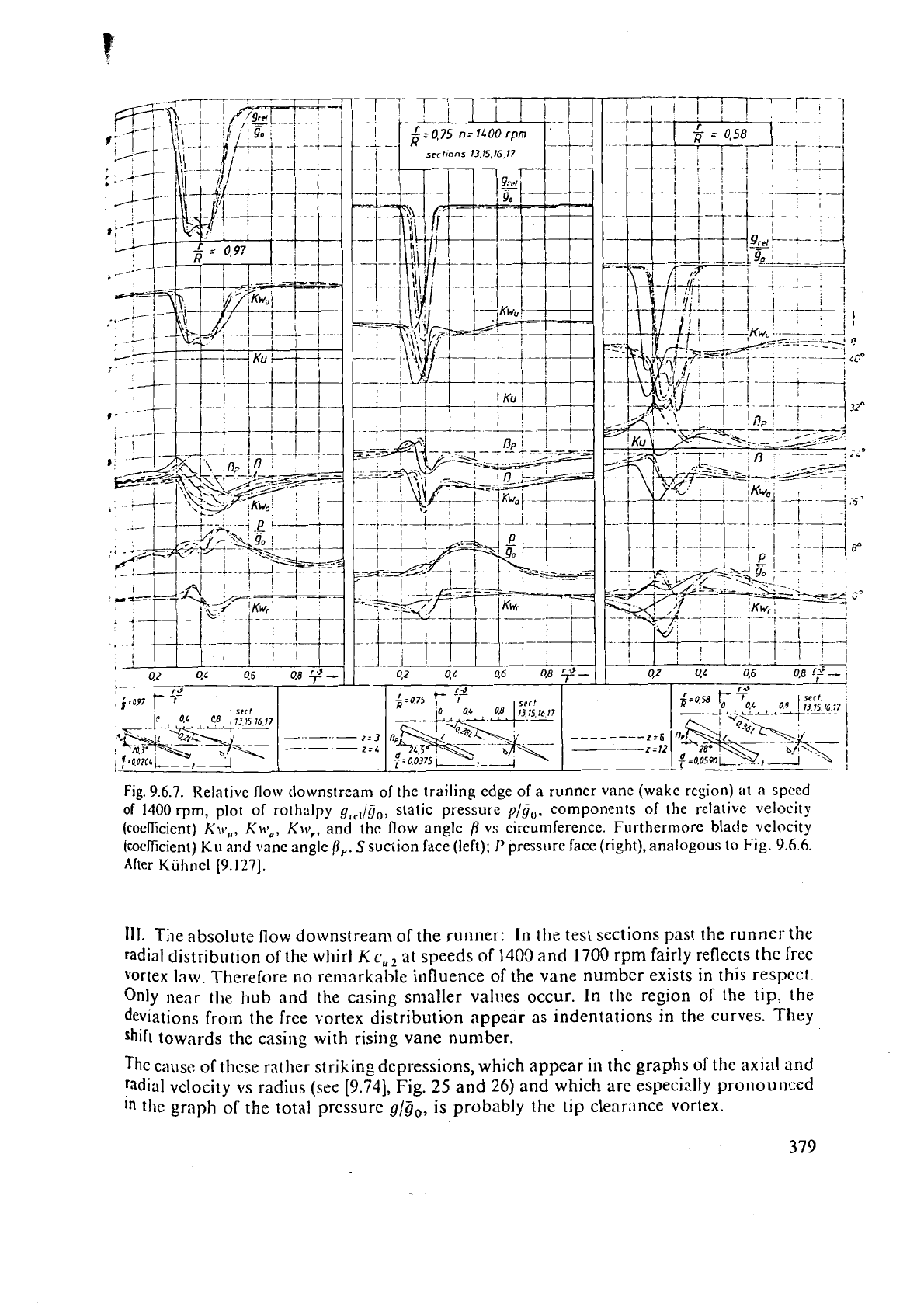
Fig.
9.6.7.
Relative flow tlownstream of the trailing edge of a runncr vane (wake region)
at
a
speed
of
1400
rpm, plot
of
rothalpy
g,,,ig,,
static pressure
p/$,.
components of the relative velocity
(coeficient)
KIV,,,
KH~~,
KIV,,
and the flow anglc
vs
circumference. Furthermore blade
velocity
fcoeficient)
Ku
and
vane angle
P,.
S
suction face (left);
I'
pressure face (right), analogous
to
Fig.
9.6.6.
After Kijhncl
[9.127].
111. The absolute flow downstream of the runner: In the test sections past the runner- the
radial distribution of the whirl
Kc,,
at speeds of
1400
and
1700
rpm fairly reflects the free
vortex
law. Therefore no remarkable influence of the vane number exists in this respect.
Only
near the hub and the casing smaller values occur. In the region of the tip, the
deviations from the free vortex distribution appear as indentations in the curves.
They
shift towards the casing with
rising
vane number.
The cause of these mther striking depressions, which appear
in
the graphs of the axial and
radial velocity its radius (see
[9.74],
Fig.
25
and
26)
and which arc especially pronounced
In
the graph of the total pressure
glij,,
is
probably the tip clearance vortex.
F<,r thc
3-
;~fid 4-\zinc rilnllcr thc zonc,
irl
which the whirl
Kc,,,
falls short
of
the \r;~lu~ for
;I
potcntiil
vortcx. cxtcntlb
at
2000
rpm nlclrc ovcr
a
mean part of thc cross scction than
it
does
IJOO
rPtn
to
1700
I
pin. thus having then
a
nearly lincnr drop of thc
\clii:l
Kc.,,
versus
r
ovcr
a
wide ran
g
or
r:~diu.;.
-1'hc
reason for these ~rnc.upcctcd irrcgul;tritics ancl also for the tlcviation near the hub is tho growth
of
the boundary
layer
under the inllucncc of centrifug:il force and r:ldi;ll prcssurc gradient. For the
spccti
I
100
rpm and espcci;llly for
SO0
rprn only the 12-vaned runner ;~pproximatcly achieves the
free
vortcx relationship. The smallcr the vanc number thc more tllc
V~UCS
of the whirl decrease near
the
casing and hub, whcrcas they grow in the mean vanc scction.
Th,- rise of the axiill vcloci~y frorn thc casing towartls the hub, cnlargcd by clccrease of speed
(set
[9.'74],
Fig.
25)
can bc explnincd also by thc resulting drift of fluid within thc bound:~ry layer towards
the axis whcn passing the runner.
.
9.6.4.
'Tl~eoretical computation
of
relative
flow
field
and
coriiparison
between
this
and
experiments
9.6.4.1.
Introduction
The probleni considered consists in the computation of the relative flow through a known
cascrtdc (indirect problem).
A
spatial singularity method was developed. This indeed allows in a sirrple manner the
fulfilment
of the
kinematic
boundary conditions on the faces of vanes, casing or
hub
but
not for the secondary How produced by the relative eddy in
a
plane normal to
the
axis
between the runner vanes.
Tht:refore :he flow gencratcd by the singularities has to be superin~poscd on the flow pertinent to
thc reiative eddy foilowing a proposal of
liutibc
[4.11],
[5.62].
[S.6],
explairled
in
Cap.
5.5.
In acc~rdnncc c.ith the assumptions rnadc with respect to the singularity rrlcthod the comparison
of
baluc, computcd and mcasurcd was lirnited to a speed
n
=
1400 rpm in the ncighbourhood ofthe
bep.
9.5.4.2.
The
spatial
sinqularity
method
I.
The model used for the bound vortices: In the following computation method the
blading is rep!aced ~vith respect to its effects
011
the ifow by spatially arranged
bound
vortices
(Fig.
9.6.8~1).
The application
of
the procedure is limited to a) small-cambered
(j','L
<
@,I),
and thin-vaned profiles
jd/Lc
0,1),
b) approximate constant runner
vanc
circulaiion along the radius, c) approximate location of the leading inlet edge and the
trailing edge
of
runner vane within rneridional planes.
The vortex filame~ts are a11 formed
by
continuously distributed elements of vortex stars. Each vortex
star consists of
1
straight-lines vortex filaments, extending from the runner axis towards
in fill it^
(Fig.
9.5.8
a).
Sincc thc bortex filaments make an angle
n/2
-
v
with the runner axis, the elementaq
vor:iccs of
an
clemci:tary star are located on the surfacc of a circular cone, whose apex on the
axu
forms the common origin of the straight-'lined bound vortices.
To satisfy
Ht~11,rholr:'s theorem, any straight vortex line of i~n umbrella-like vortex star is split
on
thC
apcx into tu.0 oppositely rotating axial vortices of the same magnitude reaching from the apex
to
both :hc ends
of
the turbine axis at infinity
(Fig.
9.6.8).
~t
Passing over the apex of thc cone of such an elementary umbrella-like vortex star from one of
ib
axial
SII~S
to the other. the circulation around the axis expel-icnces
n
step equal to the sum oft?
circu1:ltions of all the
z
vane-linked elementary vortices for
3
definite radial scction.
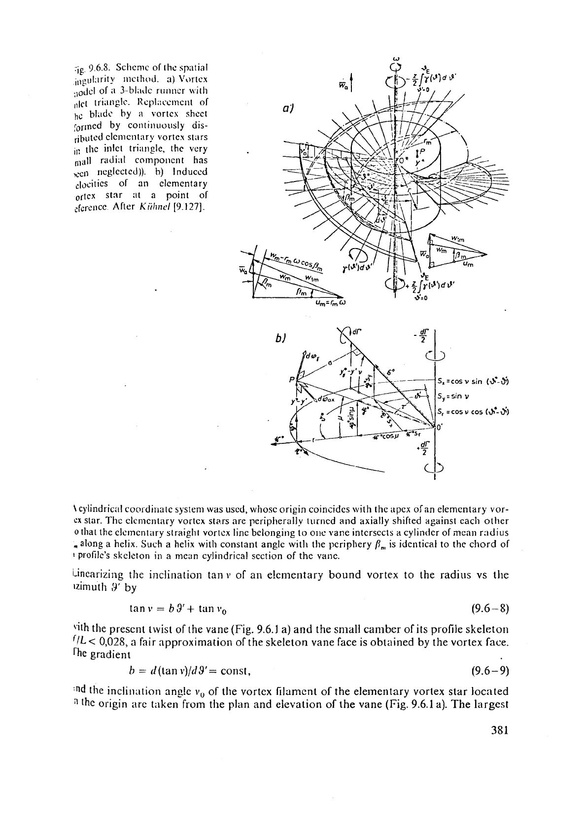
rig.
9.6.5.
Sclicmc of Illc. spatial
iIlgul:~rit~ mcthod.
a)
\'ortcx
.l,clcl of
;I
3-b1;1~1c runncr \virh
,,l,-t
tri;lnglc. 1lcpl;:cclncrlt of
hc
bli~dc by
a
vortcs shcct
ror~ned by con~ir~i~ously dis-
,jbutcd c1cnlcnt:lry vortex stars
,,:
tlic inlet triil~~gle, the very
,l;ill
radial cnmponcnt has
~CII
11egIcc1cd)).
b)
Induced
c]ocitics of an clemcntary
~rtcx star at a point of
,.ference After
k'iihr~el
[9.127].
sin
(a*-$)
cos
(a*-$)
\
cglindria~l coordiliatc systenl was used, whose origin coincides with the apex of an elementary vor-
ex
star. The clcmcntary vortcx stms are peripherally turned and axially shifted against each other
0
Illat the elcmcntary straight vortcx linc belonging to
OIK
vane intcrsccts a cylinticr of
mean
r:~dius
,along a helix. Such a helix with constant angle with the periphery
P,
is identical to the chord of
I
p~ofilc's skeleton in a mcan cylindrical section of the vane.
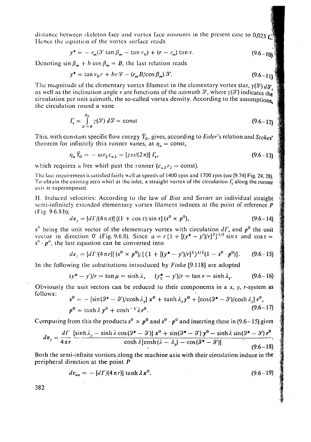
Linearizing the inclination tan
v
of an e!ementary bound vortex to the radius vs the
lzirnuth
3'
by
tan
v
=
b3'+
tan
11,
(9.6
-
8)
rith
the present twist of the vane (Fig.
9.6.1
a)
and the snlall camber of its profile skeleton
(/L
<
0,028,
a
fair approximation of the skeleton vane face
is
obtained by the vortex face.
gradient
b
=
(](tan
v)/d$'=
const,
(9.6
-
9)
:nd
the inclillation ang!e
v,
of the vortex filament of the elementary vortex star located
"hc
origin
are titken from the plan and eievation of the vane (Fig.
9.6.1
a). The largest
tfist;incc hcrwccn skclcton
fact
;lrltl
vortcx
Fact
;l~iioilnts in the
present
cnsc
to
0,023
licnce
thc cqi~ation of thc vortex
surface
scads
y*
=
--
rfll(,'Y
ti111
/jln
-
tan
yo)
+
(r
-
rffl) tiln
\I.
Dcnoting sin /Ifn
+
h
cos
/l,,
=
B,
t
hc last relation scads
y*
=
tan
vo
I.
+
h
r
13'
-
(r,,, Blcos
j3,)
9'.
1
Tiic msgnitudc of the elclncntary vortcx filament
in
the elc~~lental-y vortex star,
y(9')
:
8
4
as
\\~ll
as the inclination angle
11
are functions of tlie azimuth
3',
where
~(3')
indicates the
circulation pcr unit azimuth. the so-called vortex density. According to the assumptionq
+
ths circulation round a vane
1
This. with constant specific flow energy
Yo,
gives, according to E~rl~r's relation and
Stokes9
~
theorem for irlfinitcljl thin runner vanes, at
17,
=
const,
-
17,
Yo
=
-
o
r2
c,,
=
[Z
coj(2
x)]
&,
(9.6
-
13)
nhich requires
21
free whirl past the runner (c,,r2
=
const).
The
Idbt
recluirement is satisfied fdirly \\ell at speeds
of
14U0
rpm
and
1700
rprn
(see
[9.74]
Fig.
24,
28).
To
obtain
the existir?? zero \\hid
at
thc ~nlet,
a
straight vortcx
of
the circulali~n
1;
along
the
runner
a\is
is superimposed.
11.
I~duced
velocitier: According to the law of
Biot
and S~)~art an individual straight
wmi-infinite!y estenclcct eleme~tary vortex filanlcnt induces at the point of reference
P
(
Fig.
9
6.5
b),
(iu,
-
[tlP/(4
xcr)]
[(I
+
cos r):sin
r]
(so
x
pO), (9.6- 14)
sQbeins
the unit vector of the elementary vortex with circulation
dT,
and
the unit
vector in direction
0'
(Fig.
9.6.5).
Since
u
=
r{l
-t
[(y*
-
y')/r]2)"2 sinr
and
COST
=
s"
.
the last equation can be converted into
(ir.,.
-
[il
f.'(4
n
r)] (so
x
pO)/{(l
+
[(y*
--
y')/r]2)1'2(1
-
SO
.
PO)).
(9.6-
15)
In
thc following the substitutions introduced by
Finke
[9.118] are adopted
(y*
-
yl)/r
=
tanp
=
sinh?.,
(y;
-
yl)/r
=
tan
v
=
sinh?.,. (9.6- 16)
Obviously the
unit vectors can be reduced to their components in a
x,
y, r-system
as
fl2llo\vs:
so
=
--
[sin (9*
-
9'):cosh
I.,]
x0
+
tanh ?.,yo
+
[cos(9*
-
S1)/cosh
A,]
rO,
Con~puting from this the products
so
x
and
so
.
and inserting thcse in (9.6-
15)
gives
dl-
[sinh
i.,
-
sinh
j.
cos(9*
--
3')j
x0
+
sin(3*
-
9') yo
-
sinh?. sin($*
-
9')
r0
LIF~
=
-
-
---
4nr
cos h [cosh
(1.
-
R
,)
-
cos
(Q*
-
Q1)]
-
(9.6-
18)
Borh the semi-infinite vortices along the machine axis with their circulation induce in the
p~ripheri~l direction at the point
P
~dtl,,
--
-
[tlr/(4nr)]
tanh
Ax0.
(9.6- 19)
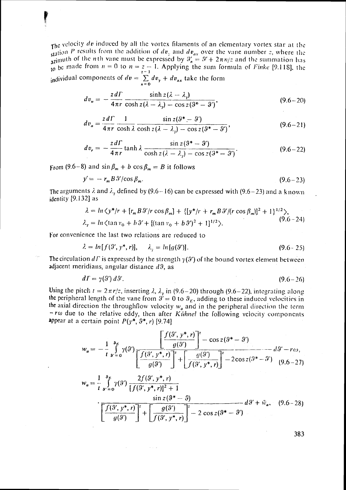
-rhc
vt'!ocity
tlv
induced
by
all the vortex filaments of an elcnientnry vortex star at tl>c
,,,l~ioii
P
WNIIIS
from
[lie :idditiu~l of
dv.,
a11d
dv,?,
over the v;ltle nomber
z,
where
11,;
3Zinloth of
tl~c
n
tli
vane n~ust bc erprcssed
by
!J:
=
8'+
2nrlj:
and thc summati011
I,:lj
to
bc
made from
rl
=
O
to
rl
=
z
--
1. Applying the sum formula
of
1-iizkc
[9.1
181,
the
z-
1
con1ponel:ts of
dv
=
C
dv,
+
dv,,
take
the
fornl
n
=
0
z
dl-'
sinh
z
(2
-
A,)
d~,
=
-
-
--
4x1-
coshz(1
-
A,)
-
cosz(9"
-
3')'
zdr'
1
duo
=
--
--
sin
z(9*,
9')
(9.6-21)
4nr
cosh
),
cosh
z(1
-
I,,)
-
cos
z(9*
-
8')
'
zdr'
sin
z(9*
-
3')
dv,
=
-
-
tanh
1.
4nr
cosh
z(i.
-
2,)
-
cos
z(3*
-
3')
'
(9.6
-
8)
and sin
B,,
+
b
cos
PI,
=
B
it follows
y'
=
-
r,,,
B
:)'/cos
fin,.
(9.6- 23)
The
ar-gun~cl~ts
i
and
i,
delined by
(9.6- 16)
can be expressed with
(9.6-23)
and
a
k1lo\vn
identity
[9.132]
as
I.
=
ln (y*/r
+
[I;,,
R
3'/r cos
/I,,]
+
([y*/i.
+
r,,,
B
$'/(I-
cos
/?,)I2
+
1
)
'I2),
I.,
=
111
(tan
v,
+
R3'+
[(tan
\lo
+
b
3')2
+
(9.6
-
23)
For
convenience the last two rclatiol1s are seduced to
The
circulation
rlT
is expressed by the stren_cth
y
(3')
of
the bound vortex elernrnt
between
adjacent meridians, angular distance
03,
as
nr
=
~(~99
nsl.
(9.6
-
29
p-------------------
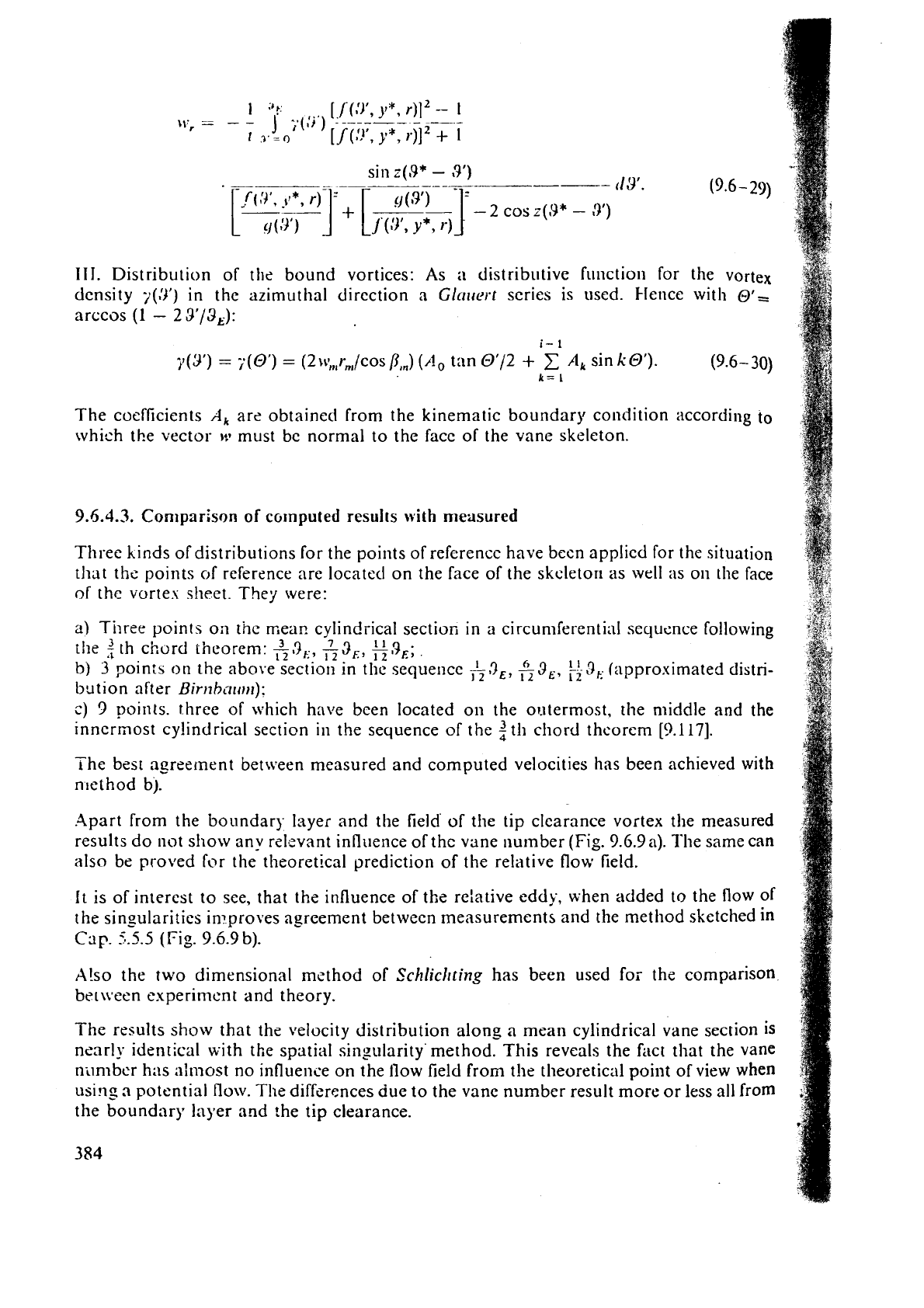
Using the pitch
t
=
2xr/;,
inserting
I.,
R,
in
(9.6-20)
through
(9.6-22).
integrating along
thc
peripheral
length
of
t!~e vanc from
3'=
0
to
19,:,
adding to these induccd \'clocitics in
the
axial direction the throughflo\i
vclocity
\ti,
and in
the
peripheral c!i~cciic>l~
tl~c
tcm
-
ro
due to the relative eddy, then after Kiihizel the following vciocity cuu?poncllts
appear
at
a
certain point
P(y*,
3*,
r)
[9.74]
1
9~
2f
(3',
Y*,
4
)1.',
=
-
j
y(9')
--------
t
9s
=O
[
f
(sf,
y*,
r)12
+
1
sin
z(9*
-
3)
--
,
(9.6-23)
f
(9'9
Y*,
sin
z(,9*
-
9')
.
-
-
(13'.
(9.6
-
29)
--
--
Y*,
111.
Distribution of the bound vortices: As
:I
distributive fitnction for the vortex
density
~(3')
in the azimuthal direction a
Glnlrei't
series is used. Hence with
@'=
arccos
(1
-
23'13,):
y
(3')
=
~(0')
=
(2
\r:,,r,,,/cos
/I,,)
(A,
tan
0'12
+
C
A,
sin
k
Of).
(9.6-30)
k=
1
The coefficients
A,
are obtained from the kinematic boundary condition according to
which the vector
)v
must be normal to the face of the vane skeleton.
9.5.4.3.
Coniparison
of
cornputed
results
with
measured
Three kinds of distributions for the points of refcrencc have been applied for the situation
that
tils points
of
reference are locatetl on the face of the skcletor~ as well
as
on the face
of
thc vortes sheet. They were:
a)
Three points on the mear. cylindrical section in a circumferential sequence following
the
3
th ci:urd theorem:
&3,,
&3,,
%,!I,;
b)
3
poin:s on the above section in the sequence
h3,,
&3,,
3,
(approximated distri-
bu
tion after Birithn~rnl):
c)
3
points. three of which have been located on the or-ttermost, the nliddle and the
innermost cylindrical section in the sequence of the
th chord theorem
[9.117].
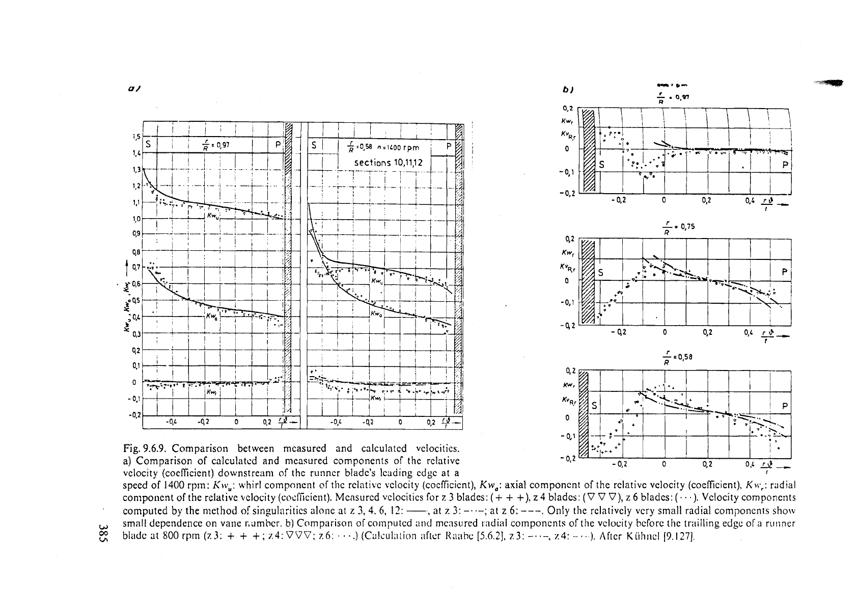
The best agreement between measured and computed velocities has been achieved with
nlethod
b).
.Apart from the boundary layer and the field' of the tip clearance vortex the measured
results do
not show any rslevant influence of the vane nu~nber
(Fig.
9.6.9a).
She same
can
also be proved for the theoretical prediction of the relative flow field.
It is of interest to see, that the influence of
the
relative eddy, when added to the
flow
of
the
singulari ties improves agreement betweer, measurements and the method sketched
in
Cap.
5.5.5
(Fig.
9.6.9b).
A!so the two dimensional mcthod of Schlicllting has been used for the comparison
bel\seen experimcn
t
and theory.
-
I
he results show that the velocity distribution along
a
mean cylindrical vane section is
nearly identical with the spatial si~lgularity'method. This reveals the fact that the vane
ni1mbc.r has n:most no influence on the flow field from the theoretical poilit of view when
usinp
a
potential flow. The differences due to the vanc number result more or less all from
the boundr~ry layer and :he tip clearance.
b
oubrm-
.Q,W
R
0,2
Kwr
KV~,r
I
0
I
-0,l
-0.2
--
I
'
x
0,75
R
0,2
Kwr
'('4
r
0
-0,l
-42
0 46
4,
t
4
2
Kwr
Kv~,r
0
-
0,l
Fig.
9.6.9.
Comparison between mcasured and calculatcd vclocitics.
a)
Comparison of calculatcd and measured components of the relative
-
0,2
-
0,2
o
0,2
O,L
--
velocity (coefficient) downstream of the runncr bladc's lcading cdgc at a
1
speed of
1400
rprn:
Kw,:
whirl component
of
thc rclativc vclocity (cocflicient),
Kw,:
axial componcnt of the relative velocity (coefficient),
Kw,:
radial
component
of
the relative ~felocity (,cocl'ficient). Mcasurcd vclocilics for z
3
blades:
(+
+
+).
z
4
blades:
(V V V),
z
6 bladcs:
(.
3).
Vclocity componcrits
computed
by
the n~ethod
of
singu1a:itics alonc
at
z
3,
4.
6,
12:
,
at
z
3:
-..-;
at
z
6:
---.
Only the rclativcly very small radial
components
show
small dependence on
vane r,ilmhcr.
b)
Comparison of computcd atid measured 1.adiol componcnts of tlic vclocity bcforc thc tr;~illing edgc
ofa
runner
bladc
at
SO0
rprn (z3:
+
+
+
;
z4:
VVV;
z6:
.
.
.
.)
(Calc~~l;~tion i~ftcr
1tx1bc
[5.6.?],
z3:
-.
.-,
z4:
--
.
-.).
Aflcr
Kiihncl
19.1271.
&-
-+
9.7.1.
Introduction
6
A
non axisy~ii~nctric and p~ils:iting :ibsoli~tc
llow
is p~-oducc~l pi~st tlre goidc npp:lrotuS
a
w;lter ti~rbine
liy
the \v:ikes olils irliirl gcncr:ltiiig c!c~ir~~~ils lhpi~.:il c:iiinf. stay :~nd
guide
va~lcs). Th11s
;I
pcriodiciill!~ or ri~~idonily p~ils:iti~ip rel:ili\;c
flow
:ll)pc:irS io tlic
rullny
vane cllanriels and
;IS
:I
consctjilcncc unstciidy \.:liic lo;ldiiig
iilii~:li
freclucotly leilds
to
vane or macilinc vibratiorl. ci\llsirig
fatigue
c~.;icks or in tltc
\\!oI.s[
c:ise
:I
rllpture
rll,,ner
vancs, [hen
t;)und
in
the draft tube.
Sevzri~l ni~tiiors.
e.?.
.\lullci~liip/
[Ll.4h].
(;~ric/~
[Y.
1331,
Sc~/~lc~rrii~l~r.
15.
IS].
:III~
C'[l.sfoi.p/~
[9.8\
;
9.1
16,
h~rvc
prove,.! b~
rncasurir~icrits
antl
obscr\ations
011
K:iplan
:11:d
I~'l~ar~cis-tt~ri~i~ics
[hc
~'~ist~~~~
d
!luctuati:ig
t:.;11:c
or
stall
31.ci1s
in
tlic
absolute
nunr
p:~ttcrn
~ntl
:11\0
ill
tile
st'l;~tivc
flow
pallcrn
h'ejrlp
and
Sc,trr..s
[6.30]>
Ku~r~cor
[9.13-1]3
and
1,0/:
(6.281
II;IW
cilrricd
out
I'i~ncl:~nicntal
rcsc;lrcll
thc
dctcrrnin;~tion
~.f
thc
rn~:t~~:iI
inllucncc
of
acljiiccnt
blade
ro\\.s
\\hc~i
the!.
I~O\.C
rclaiivc
to
tach
othcr
also
il?
the
cirbr:
of
SP~IL~LII
!low.
,4ccording to the
simplified
statcnients of tl~c rcsuarch iisork cassicd out. the intlurnccs
or
unsteady floiv in boundary layers prudi~ccd by the c1,cnt.; in t1:c maill flow must be left
out of consideration.
An
exact dctcrrninotion of iinsteady v:lnc forces rcqi~i~.cs !<rlu\\'lcclgc of the uiistc~dy
dytianic pressure i~ctin~
on
the vanc klccs ivithin the boiin(.!ary I:~;.cr. Tlie
principal
subject
of thc rolioi\.ing sectiori is the tly~i;i~iiic jiiuasilrciiiellt
01'
the c~nstetidy flow
near
to
the runner v:ii:es a:itl tviihin their bouncin~.).: layer-s in thc case
of
axial and mixed
flow
I
Francis) ti~sbines.
9.7.2.
Expc~.i~it.nts on
a
liaplan
nntei.
turbine
nod el
1.
Four port p;-obt. with q11ick response: 1--or ihc annlj.sis of this 11nste:~cly boundary 1;lycr
flow
a
suit::blr instrulnenr l~aa been
developed
by
F~~-t/wt.
3.t
1,elisstulll
~~nd
J..nbor
fiir
h~,draulischc. Maschinen und Anlrr~en. TU hliincht.11. \Vest Gei.m:iny.
(Fig.
9.7.1
a)
[9.135].
As
it
is ne,ir to the \\,all. the
flow
ic'as :tssunzd to
bc
p:irallel to :hc known
wall
face. Mcncz o~ily Fdur por!s 1i'cre ncedcu for
the
sim~iltancoiis nic:isurenlcnt of the spatial
i.slocity \rt.cto~.
and
the stitiic pressure. The port
B
\vas t~secl for [he tot21 pressure, ports
.-l
and
C
for
tlit.
!,an
angle the \,elocity makes \vith the axis of
the
probe's
hc;ld
and
the
port
D
for itle static pressure. (Fig.
9.7.1
a).
Each port
iir:~s connected
11
~tii
;I
Kulite trnnsducer, dcccribecl in
9.5.
TIIC probe could
bc
shiftcd in btep;
of
0
05
mni
bj
hand.
111
a Iatcr version,
11sed
on
the
FT.
this probe could
be
adji~sted
'on
s~te' by
a
Ioc'h at draft tube elit. Then llr. i\'~.iryl from the above institu-
tion
cfc~elo.7peci n hjclrostatic ;ictllatoi.
15
mnl high
:ind
of
20
lrlni di~trncter.
on
the
vsnc
'KC
opposite
to
that needed for merlsurcment and supp11t:d
by
pipes hid in smoothly
c~-~.ercJ grooies in th~ \Inlie. co~tii~i~ from
;i
?itr\~io~l~~~ i;cs\ci
vi:~
a
transmitti112 chamber
around
the sli:ift.
A
uVc.rrn and locking ge:tr
in
the iictuator enitblcd
a
steptvisc shift
of
the
probe by remote control
[9.83;
9.131,
Fig.
9.7.1
b.
11.
bleasoring points: Msnsurements were 1n;lde
on
;L
runner mirh
4
vanes. diameter
'
D
=
6
12
mni.
i~t
be€ \ifit11
Ii,
,
=
127,j
rpm
and
Q,
,
=
1.39
1il3/s. On each
sidt:
of the vane
9
measuring points itrere pro~,ided,
3
eltcI.1
at
i~ltersections
\i1it1l
three different coaxial
cyl-
,
