Pump Handbook by Igor J. Karassik, Joseph P. Messina, Paul Cooper, Charles C. Heald - 3rd edition
Подождите немного. Документ загружается.


2.52 CHAPTER 2
FIGURE 23 Shut-off power coefficient
The design task therefore resolves itself into an iteration between an efficient geometry-
generating scheme and a rapid CFD flow and performance analysis of the geometry
resulting from each iteration
48
. This is especially useful if a non-traditional geometry is
involved, or if an efficient design is sought that will produce a desired performance curve
shape. Nevertheless, many turbomachinery designers can make more rapid and valid
judgments about their respective classes of machines through the time-honored iteration
between a proprietary direct or inverse design and performance-prediction scheme and
inviscid quasi-3D analysis
41,43
. They have developed reliable diffusion criteria (computed,
for example, from Eqs. 59a and 59b) for interpreting the acceptability of the free-stream
relative velocity distributions W
s
and W
p
on the blade surfaces (Figure 17) produced by the
Q3D blade-to-blade solutions
43
. Because CFD codes solve the actual viscous flow field, the
boundary condition on the blade surface is zero relative velocity. This can be at least partly
overcome by displaying the CFD-distributions of pressures on the blade surfaces, the
interpretation of which would require knowledge of the corresponding criteria for these
pressures
46
. Also, the velocities at the edge of the boundary layer could be extracted from
the CFD solution and displayed in familiar terms. A useful design approach for the present
may therefore be to a) produce the final design by the more traditional methods and b) pre-
dict the performance curves via CFD
49
.
Predicting Axial Thrust The prediction of pump performance is not truly complete
without the corresponding prediction of the hydrodynamic axial and radial thrust that the
impeller(s) can be expected to encounter. A comprehensive treatment of radial thrust
appears in Section 2.3.1, and a review of axial thrust and thrust balancing devices is cov-
2.1 CENTRIFUGAL PUMP THEORY 2.53
TABLE 4 Leakage effects on axial thrusts
ered in Section 2.2.1. However, obscure flow phenomena can profoundly affect the radial
distributions of pressure on the outside surfaces of a shrouded impeller that give rise to
the net axial thrust. These phenomena become even more complex when discharge recir-
culation occurs and can cause adverse mechanical response in high-energy pumps, as will
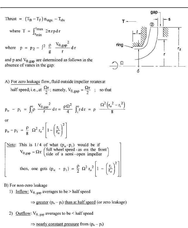
be explained further on. As a basis for tackling such problems, the fundamentals of axial
thrust are presented in Table 4 for shrouded centrifugal impellers that have leaking fluid
flowing in the gaps between the impeller shrouds and the adjacent casing walls. The pos-
itive direction of the thrust T is taken toward the suction or eye of the single-suction
impeller shown. The incoming axial momentum rQV
z,1
is generally quite small for radial
impellers and has been omitted from the Table. It serves, however, to reduce T.
The centrifugal effect of the fluid spinning in the sidewall gaps causes a reduction in
static pressure from the outer periphery (OD) of the impeller to the sealing ring, and this
2.54 CHAPTER 2
TABLE 4 Continued.
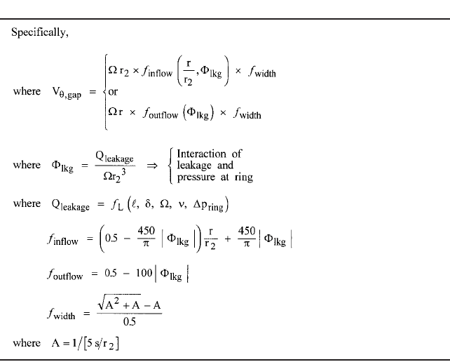
is quantified in the expressions given for the swirl velocity component V
u
. These expres-
sions are curve fits to experimental data for the leakage flowing radially inward on either
or both sides of the impeller
50
and for outflowing leakage as occurs on the back side (away
from the “front” or suction side) of multistage pump impellers due to the higher pressure
arising from the diffusing system downstream of each impeller
51
. In the absence of leak-
age, the fluid in the sidewall gap rotates at about half the local impeller wheel speed; that
is, V
u
r/2, and this half speed is typical of the gap flow near the impeller OD, even in
the presence of leakage.The greater the inflow leakage, the lower the pressure becomes at
the entrance to the ring clearance. The major effect is that of swirl or the tangential com-
ponent of velocity V
u
, which varies inversely with radius unless casing wall drag interferes.
More leakage flow is less influenced by this drag and so experiences a greater centrifugal
effect. This in turn means more pressure drop from OD to ring. (The leakage rate, of
course, is affected, the solutions for both leakage and pressure distribution being linked
and usually requiring iteration.) The opposite effect happens for outflow on the back side
of multistage pump impellers. Here the fluid enters the sidewall gap at a small radius (see
Section 2.2.1) and so with negligible swirl. It flows outward without picking up much swirl,
especially if there is substantial radial outflow leakage, which means the centrifugal effect
is small, yielding a nearly constant pressure versus radius. The overall result is more net
thrust than might be expected from a cursory look at the pressure-loaded surfaces.
If wear ring clearances increase during the life of the pump, the net thrust of multi-
stage pump impellers increases. Likewise, unequal ring wear leads to uncertain changes
in the thrust of a “balanced” single- or double-suction impeller with inflow to wear rings
on both sides. Similarly, these theories can be applied to balancing drums and other such
devices described in Section 2.2.1.
Integration of the pressure equation in Table 4 becomes a chore unless the whole the-
ory is computerized. A quick estimate of the thrust is possible, however, if the distributions
of pressure in the separable domains of the surfaces are assumed to be linear; in that case,
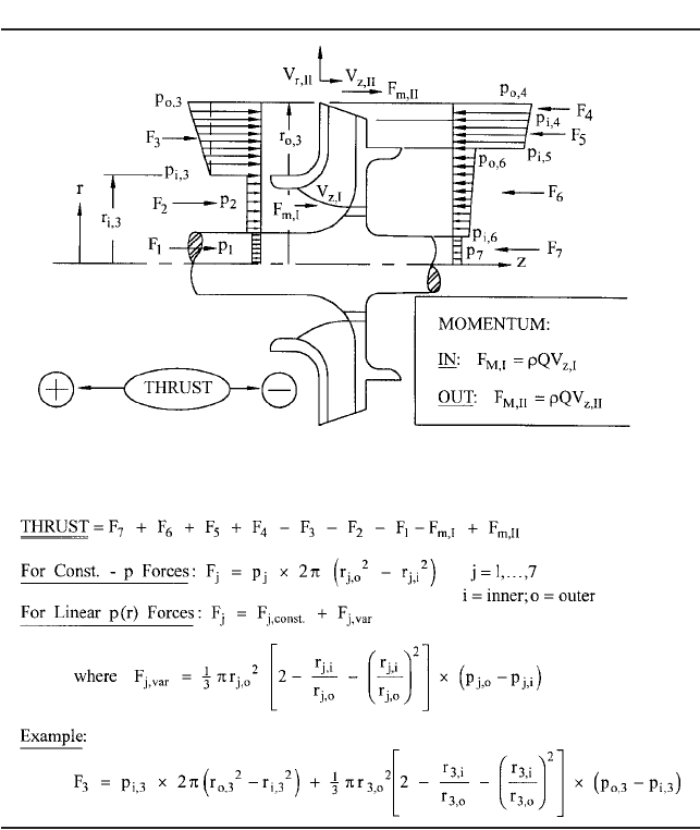
2.1 CENTRIFUGAL PUMP THEORY 2.55
TABLE 5 Approximate axial thrust calculation
the integration is simple and yields the closed-form results of Table 5. This table also indi-
cates how to account for each element of the thrust, including the axial momentum terms,
which become significant for higher-specific-speed mixed-flow impellers. In all cases, in
order to proceed with the calculation, the static pressure at the impeller OD must be
known, as it is from the boundary condition imposed at the OD that the rest of the pres-
sure distribution emerges. Even for substantial leakage, the pressure drop of the fluid
entering the sidewall gaps from the impeller exit is small or negligible; therefore, the
impeller pressure essentially applies in the gap (at the OD) as well. The foregoing meth-
ods of predicting pump head also yield the impeller OD pressure, which is usually between
75 and 80% of the stage pressure rise above inlet.
Thrust computations can therefore be coupled with the head-curve prediction scheme
being employed for the pump, thereby yielding predicted thrust curves together with the
predictions of hydraulic performance.
2.56 CHAPTER 2
Ensuring Stable Performance The ability for a pump to run smoothly with minimal
pressure-rise and flow-rate excursions is dependent on the shape of the pump head-flow
performance curve and the characteristics of the system in which it operates. There are
two types of pump-system instability; namely, a) static instability, which can be ascertained
by studying the pump and system head curves, and b) dynamic instability, which requires
more detailed knowledge of the system
52
. (In addition to these system-related instabilities,
there is the unsteady behavior of the separated and recirculating flows that occur when a
pump operates a flow rate substantially below the BEP. Called hydraulic instability, this
becomes important in higher-energy applications and is therefore discussed later.)
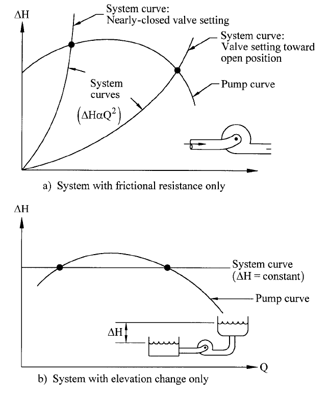
a) Static stability and instability. Figure 24 illustrates two pumping systems; namely, a)
a piping system in which the flow is turbulent and largely independent of Reynolds num-
ber; so, the head drop H through it is proportional to Q
2
, and b) two reservoirs with a
constant difference H between the two liquid surfaces and comparatively negligible head
loss in the pipes connecting them. In each case, the pump is designed to produce head H,
as required to deliver the desired flow rate Q.The influence of the pump head curve shape
is immediately appreciated in Case (b): the curve “droops” as Q is reduced to shut-off,
thereby producing two vastly different flow rates at the same head. In fact, however, the
pump will not operate at the lower-Q intersection point of the two curves.The pump shut-
off head is less than H, so it will produce no positive flow rate. Instead, as discussed in
Section 2.3.1, fluid will flow backwards through the pump. Further, if circumstances could
allow operation at this lower-Q point, even a vanishingly small increase of Q would cause
a further, divergent increase because the head of the pump exceeds the H of the system.
Likewise, a small decrease leads to even lesser Q because the system H exceeds that of
the pump. This is called “static instability.” Conversely, the higher-Q point of Figure 24b
is “statically stable,” small departures in Q being suppressed by algebraically opposite
signs of the difference between the system and pump heads. Both intersection points of
Figure 24a are seen by this type of analysis to be statically stable. If the operator increases
the frictional resistance by closing up a valve in the piping system, the operating point
simply moves to the left on the curve and remains stable. Thus, it is concluded that if the
slope of the pump H-versus-Q curve is less than that of the system, operation will be sta-
tically stable
—
and vice versa.
Most pumping systems are combinations of the “pure friction” type of Figure 24a and
the “purely elevation” type of Figure 24b. In this case of static stability, the drooping pump
head curve presents no problem. Theoretically, it is possible to have a pump head curve
with a kink that could have a more positive slope than that of a system curve, which might
intersect it at such a kink. The high-
s
curve of Figure 22b depicts a kink or dip, which is
due to stalled flow within a mixed- or axial-flow impeller that is not sufficiently confined
by the impeller to be maintained in solid body rotation. (It is the centrifugal effect of such
rotation that maintains the pressure rise in radial-flow impellers despite the stalling.)
That particular pump, if applied to a system that never intersects the pump head curve at
the kink, would never experience static instability. On the other hand, the designer may
want to take on the challenge of designing a machine without such a kink. The previously
mentioned design procedure utilizing CFD in both the impeller and the diffuser to check
whether the kink is gone would be a way of tackling this problem
53
.
In-depth discussion of the variety of systems that can be encountered, including mul-
tiple systems and parallel operation of multiple pumps, can be found in Sections 2.3.1, 8.1,
and 8.2. Purely from a static stability standpoint, most of these situations demand a sub-
stantially negative slope of the head curve throughout the range of flow rate Q
—
or what
is commonly specified as a pump with head “continuously rising to shut-off.” (This “rise in
head” versus a drop in Q should not be confused with the pump developed head H, which
is also properly termed the “head rise” H, produced by the pump at a given value of Q.)
b) Dynamic instability. If the system has appreciable capacitance, operation may not be
stable if the slope of the pump head curve is positive or even zero
54
. This is true even
though the slope of the pump head curve is less than that of the system head curve as
required above for static stability
—
as with the lower-Q intersection point of Figure 24a.
Dynamic instability can be manifested as pump surge, a phenomenon wherein the flow
2.1 CENTRIFUGAL PUMP THEORY 2.57
FIGURE 24A and B Pump-system stability
rate oscillates and can even be alternately positive and negative through the pump
54
. This
is characteristic of “soft” systems that contain vessels with free surfaces and, therefore,
appreciable capacitance. Two-phase flow increases the capacitance of a system and can
cause dynamic instability. For example, fluctuating vapor volume within the propellant
pump inducers can contribute to the dynamic instability of a rocket propulsion system
55
.
On the other hand, a “hard” piping system with no capacitance is theoretically capable
of accommodating a pump that has a flat or drooping head curve and that operates on that
flat or drooping section of the curve. Low-specific-speed pumps can have drooping curves
(Figure 22b), especially if designed with a high head coefficient c at the BEP. Figures 5
and 7 of Section 2.3.1 depict flat and drooping curves of low-
s
radial-bladed pumps, a type
that is widely used in low-cost, small sizes. If properly applied, such machines will oper-
ate with stability. On the other hand, a conservative approach that guarantees both static
2.58 CHAPTER 2
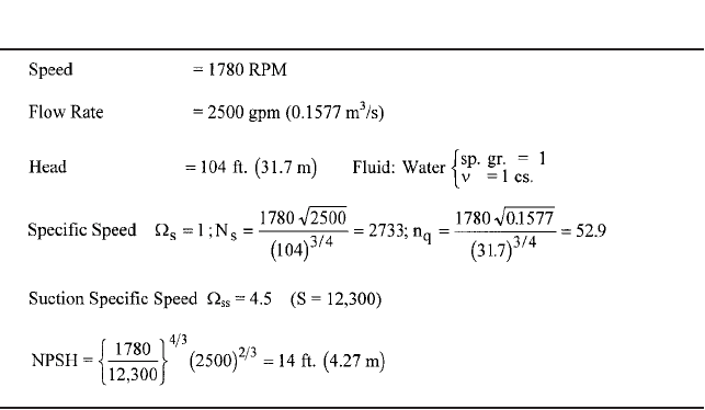
TABLE 6 Given conditions for design example (single stage, end-suction volume
pump)
and dynamic stability for the widest range of applications is to design all pumps without
flat spots or droops in the head curves.
DESIGN EXAMPLE ___________________________________________________
To illustrate the application of the preceding design information, the basic hydraulic design
requirements are presented in Table 6 for a single-stage centrifugal water pump with a
volute collector. The chosen conditions compute to a universal specific speed
s
of 1 (N
s
2733, and n
q
52.9 from Eqs. 38a and 38b). The pump is to be designed for a suction spe-
cific speed
ss
of 4.5 (N
ss
K S 12,300 by Eqs. 41 and 42), therefore, a “performance-NPSH”
(see NPSH discussion in Section 2.3.1) or NPSH
3%
of 14 ft (4.27 m). As such, this pump is
readily applicable to taking water from an atmospheric reservoir with some suction lift.
Although acceptable for 1780 rpm specified for this pump, this suction-specific speed
ss
of
4.5 is regarded as high for pumps with more head (energy level) than this one (see the
energy-level discussion later).
Impeller Design
SUCTION NOZZLE Beginning upstream, an ideal, axial-flow approach passage is assumed
—
this is known as an “end-suction” configuration. The suction-approach passage or suc-
tion branch (not shown) is simply a conical nozzle that increases the velocity of the fluid
from the suction port to the impeller eye by about 50 percent in an axial distance of about
half the diameter of the eye. This helps to ensure the existence of uniform flow at the eye.
Too short a nozzle would mean excessive local meridional (axial in this geometry) veloc-
ity at the impeller shroud and possible separation.
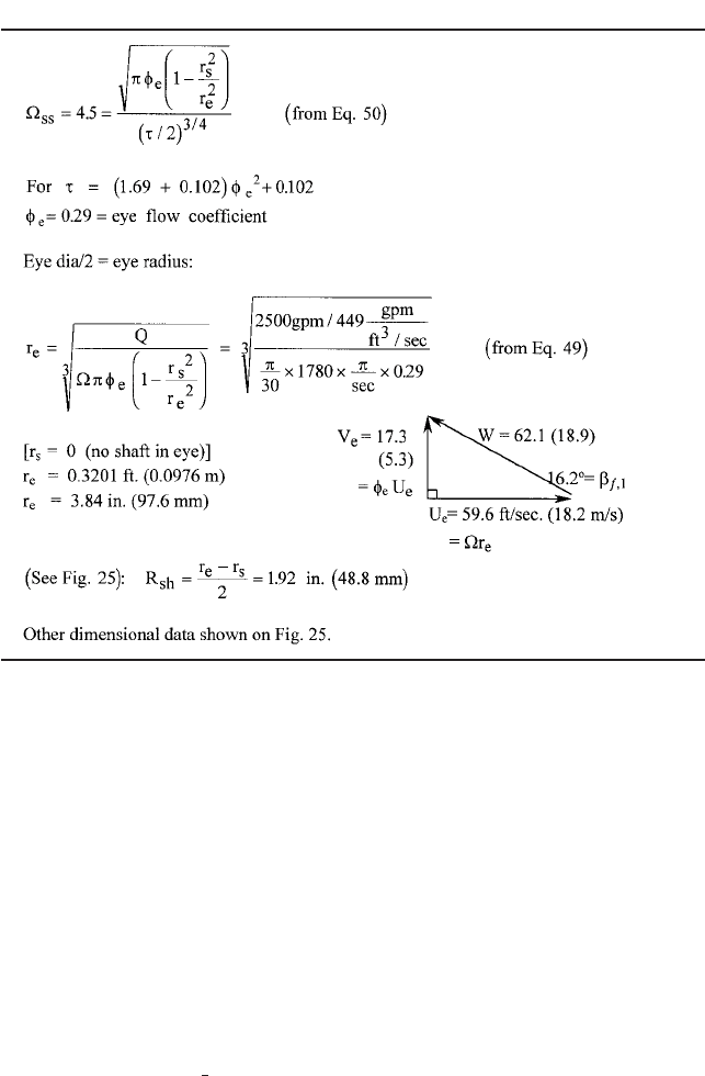
IMPELLER INLET Beginning with
ss
of 4.5, computations for this example are carried out
in Table 7 for the impeller eye geometry. The choice of the NPSH
3%
correlation of Table 1
is used, with k
1
1.69 and k
2
0.102. The local maximum velocity at the eye V
1,sh
(V
m,1,sh
)
is assumed to be 25% greater than the one-dimensional average V
e
Q/A
e
. This is smaller
than the bladeless result of Figure 14, but is typical of this end-suction configuration,
2.1 CENTRIFUGAL PUMP THEORY 2.59
TABLE 7 Impeller inlet (design example)
including the effect of the blading. Moreover, the value of k
1
should be more than adequate
for this value of V
1,sh
.
The
ss
and t-f
e
relationships yield the eye flow coefficient f
e
, which in turn sizes the
eye. f
e
0.29 implies a t-value of 0.253, which is typical. However, lower f
e
- and t-values
are common, especially for the case of a shaft through the eye, because this tends to main-
tain the level of
ss
in the face of the r
s
-effect in Eq. 50. The nominal velocity diagram at
the eye
—
substantially the shroud-end or tip of the blade leading edge
—
shows V
e
rather
than V
1,sh
for the meridional component of velocity and so is not the actual velocity dia-
gram at that location. Rather, this triangle serves to identify the geometry through the
basic ratio f
e
V
e
/U
e
—
without having to deal with the uncertain choice of V
1,sh
/V
e
. More-
over, f
e
is the tangent of the tip relative flow angle b
f, 1
as it would be for a uniform axial
velocity profile in the eye.
With the eye radius r
e
established, the local shroud radius of curvature R
sh
follows from
the guidelines associated with Figure 13. The geometry established so far is illustrated in
Figure 25. Before the full picture shown there can be established, the outlet must be sized.
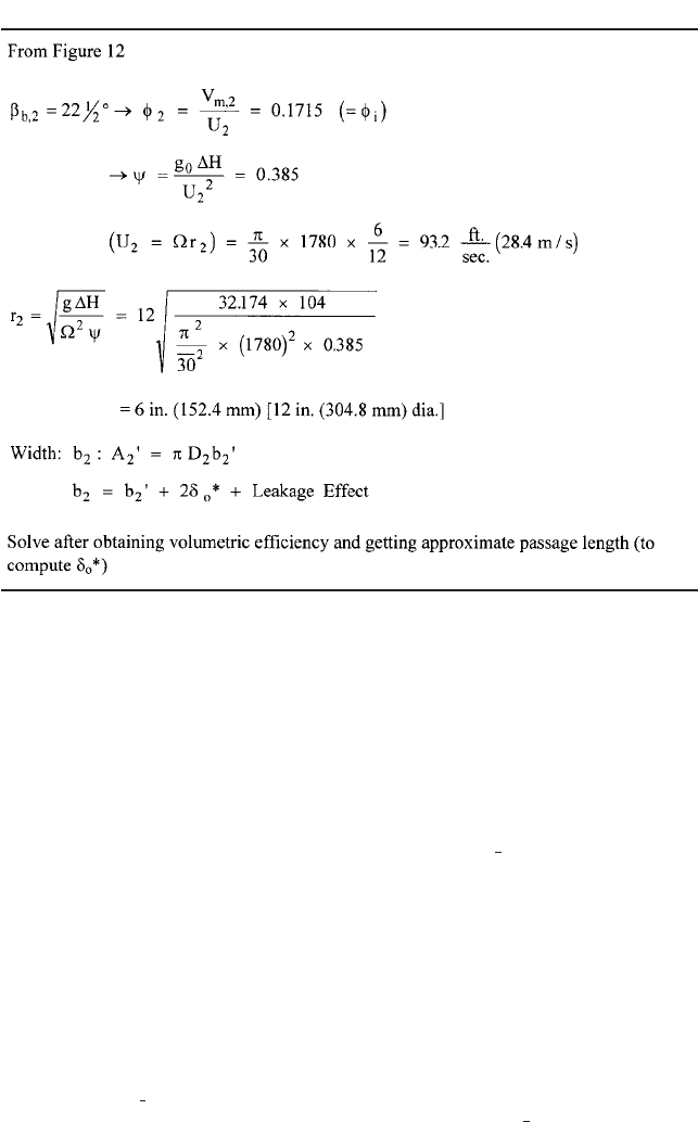
IMPELLER OUTLET The computations in Table 8 for the impeller exit begin with the choice
of the typical value of 22 degrees for the outlet blade angle b
b,2
. This enables the head
coefficient c to be chosen under the guidance of the upper curve in Figure 12. The value
0.385 is selected, and this yields the impeller diameter of 12 in. (304.8 mm). The other
curve in Figure 12 is for outlet flow coefficient f
i,2
, which conveniently equals 0.1715 for
1
2

2.60 CHAPTER 2
FIGURE 25 Impeller hub and shroud profiles (design example)
s
1. This leads to the exit width b
2
after adding in the leakage and the blockage of
blades and boundary layers per the computations of Tables 9 and 10.
However, Anderson
6
points out that what matters for centrifugal pump performance is
neither the blade angle nor the exit width individually, but the impeller outlet relative
area 2pr
2
b
2
sin b
b,2
. Choosing a higher blade angle is possible if b
2
is correspondingly
reduced (and f
i,2
increased) so as to maintain this area and therefore the relative velocity
W. Figure 15 shows that V
u,2
is thereby essentially unchanged; this in turn preserves the
impeller head.
EFFICIENCIES Anderson’s overall pump efficiency correlation (Figure 10 and Eq. 44) and
the component efficiency expressions of Table 3 lead to the results of Table 9. These give
an indication of the relative magnitudes of the losses and are as follows:
Overall efficiency h
p
0.8550
Mechanical efficiency h
m
0.9814
Volumetric efficiency h
v
0.9833 (leakage across front and back rings)
Hydraulic efficiency h
HY
0.8860
h
HY
is at this point simply deduced from the others, beginning with Anderson’s corre-
lation. Although it is confirmed by Jekat’s correlation in the table, it can be found in a
2.1 CENTRIFUGAL PUMP THEORY 2.61
TABLE 8 Impeller outlet (design example)
detailed computation of the hydraulic losses via one-dimensional methods. This will be
carried out further on to obtain the performance characteristic curves. Meanwhile, this ini-
tial computation enables the determination of V
u,2
at the end of Table 9, which, along with
V
m,2
from Table 8, is a major element of the outlet velocity diagram of Figure 26.
BLOCKAGE AND WIDTH AT IMPELLER EXIT With the leakage and exit blade angle information,
Table 10 contains the computations of the blockage and the exit width b
2
. This entails the
choice of the number of blades, the blade thickness t (2% of the impeller diameter and typ-
ically assumed to exist at the exit and elsewhere on the blades except near the leading
edges where typically half that value is chosen), and the approximate blade length /
(assuming the mean-streamline blade angle to be constant at 22 deg). The boundary layer
blockage is computed from the following approximations:
• Adverse pressure gradients on the blades lead to a boundary layer displacement thick-
ness
*
of twice the zero-pressure gradient value
0
*
on each blade surface.
• Secondary flows scrub the boundary layers from the hub and shroud surfaces; so,
*
is
assumed to be equal to
0
*
on those surfaces.
•
0
*
0.0462 /
0.8
n
0.2
/W
0.2
for flat-plate, turbulent flow
56
, and is approximated in this
example for low viscosity by a linear growth with length along the blade.
The resulting thickness of the boundary blockage is 0.0732 in (1.86 mm) on the blades,
which themselves have a thickness of 0.24 in (6.1 mm). Because these thicknesses are
inclined at the 22 -deg outlet angle, the actual circumferential blockage is (1 e
2,b
) (1
0.870) or 13 percent of 2pr
2
. In particular, (0.24 0.0732)/sin (22 deg) 0.82 in or (6.1
1
2
1
2
1
2