Pump Handbook by Igor J. Karassik, Joseph P. Messina, Paul Cooper, Charles C. Heald - 3rd edition
Подождите немного. Документ загружается.


2.72 CHAPTER 2
FIGURE 31 Damage to impeller from low-flow operation (Source: E. Makay in Power)
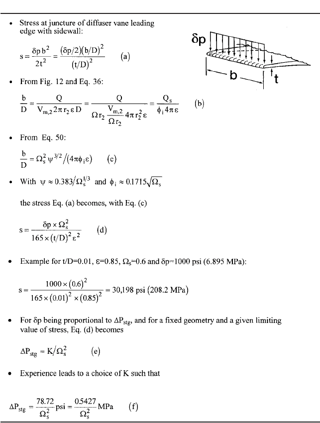
emerges in Eq. (e). The constant K is chosen from experience, which leads to the result-
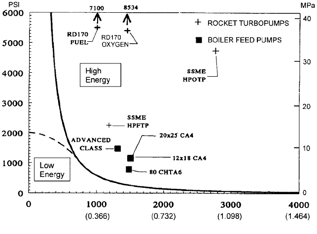
ing Eq. (f). This relationship is plotted in Figure 32. [It will be observed that this choice
for K corresponds to a limiting stress s from Eq. (d) of 6,600 psi (45.5 MPa) that would
exist if dp were equal to P
stg
—
with t/D 0.01 and e 0.85 as in the example.] The
inverse variation with specific speed is a consequence of the greater b/D of higher-
s
pumps (as developed in Table 12), the wider vane introducing more stress at the juncture
with the sidewalls for the same pressure loading and so imposing a lower stage pressure-
rise limit. Conversely, lower-
s
pumps should have higher limits for P
stg
.
Figure 32, therefore, illustrates this concept of a limiting stage pressure rise as a mea-
sure of the energy level of centrifugal pumps, the basis being a limiting stress level in a
critical component of the pump. Starting with stress at other locations in the pump leads
to similar results. To provide perspective, specific examples of pumps that by this defini-
tion are in the high-energy domain are plotted on the figure. These data points are taken
from Table 13, which contains information for several well-known liquid rocket engine
turbo pumps
62,63,64
and for some representative high-energy electric utility boiler feed
pumps
53,57
.
The last column in Table 13 is another, more general way of comparing the energy level
of these machines; namely, the torque per unit volume, which also has the dimensions of
stress. For fixed ratios of stage width, casing OD, and other dimensions to impeller radius
r ( r
2
), torque per unit volume differs from the listed values of torque/r
3
by a factor. The
actual torque per unit volume therefore ranges from one-half to one-sixth of the tabulated
2.1 CENTRIFUGAL PUMP THEORY 2.73
TABLE 12 Hydraulically induced stress levels
torque/r
3
, depending on the casing or barrel thickness, and so on. However, as has been
demonstrated, the critical stresses are more closely associated with the impeller OD,
which makes comparison of the tabulated values more relevant. Thus, a pump with high
torque/r
3
can be expected to have correspondingly high local internal stresses. The maxi-
mum values listed, namely for the high-pressure propellant pumps on the RD-170 (Russ-
ian) and SSME (U.S. Space Shuttle) engines, tend to explain the high level of research and
development that was necessary to successfully deploy these machines. Illustrations of
some of these rocket engine pumps can be found in Section 9.19.2. Similarly, Section 9.5
2.74 CHAPTER 2
FIGURE 32 Pump energy level defined in terms of stage pressure rise
provides examples of high-energy boiler feed pumps: the massive, barrel-type construction
of these machines is illustrated in Figure 18. Specifically, the first boiler feed pump listed
in Table 13 is the sole feed pump supplying the steam generator of a super-critical 1300
MW electric generating unit and consumes nearly 50 MW of shaft power. It can be seen in
Figures 7 and 20 of Section 9.5.
For pumps in the low-energy domain of Figure 32, normal design and manufacturing
practices result in a more benign mechanical response to the abnormal fluid phenomena
discussed here. However, for locations other than the diffuser entrance, which was the
basis for the development of the figure, limiting stresses could be reached at considerably
lower values of stage pressure rise. For this reason, the dashed line is offered as the upper
limit of the low-energy domain; however, a thorough analysis of the stresses in any given
application is the ultimate determinant of all the limits suggested in Figure 32 and of the
acceptability of the design. It can now be seen that the design example treated earlier in
this section is of the low-energy variety; therefore, the special design problems treated
here and further on are of relatively little concern in such pumps. On the other hand, if the
curve in Figure 32 were extended to much higher specific speeds, it would be found that
many existing, large, high-
s
, low-head pumps are high-energy machines by this stress-
related definition. It is therefore not surprising that such pumps generally require full
stress and modal analyses to identify possible destructive resonances and stresses.
Fluid/Structure Interactions With the dimensions of pump energy level identified, the
next step is to continue the examination of the problems mentioned previously and the
methods that have become available for solving them. Attention is focused on hydraulic
phenomena because, as the previous discussion of pressure pulsations implies, most of the
adverse mechanical behavior exhibited by pumps originates from the behavior of the inter-
nal flow field. Excessive measured vibrations, material erosion, and component failures
are often the external symptoms of fluid/structure interaction phenomena that are fun-
damentally explained from a hydraulics perspective. In addition to the hydraulically

2.1 CENTRIFUGAL PUMP THEORY 2.75
TABLE 13 Data on high-energy pumps*
induced stresses in the pump structure that culminated in the domain definition of Fig-
ure 32, these phenomena encompass a) blade-vane interactions, b) recirculation, c) anom-
alous axial thrust behavior, and d) cavitation.
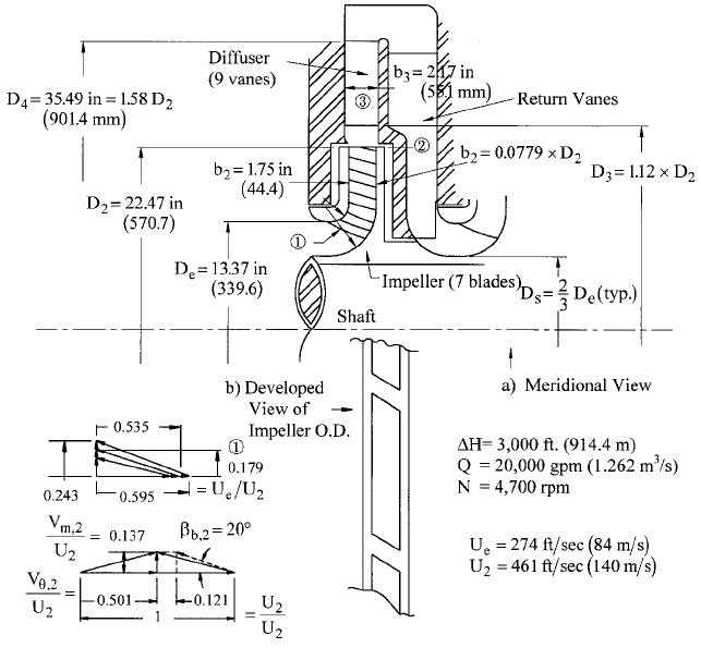
In order to illustrate the methods for dealing with the problems created by these
fluid/structure interactions, a sample suction stage of a high-energy multistage pump is
utilized as the quantifying focus in each case. Table 14 contains the conditions and essen-
tial features of this machine, a meridional view of which is shown in Figure 33.As with the
earlier design example, this stage has been designed in accordance with the procedures
outlined for that example.This includes the velocity diagrams shown in the figure, as well
*Notes to this table: Flow rates apply to the pump inlet. RD-170 pump data derived from
Sutton
62
and Advanced Class boiler feed pump data from Ref. 57. Remaining data derived from Table
1 of Section 9.19.2, NASA reports
63,64
and from information supplied by Flowserve Corporation.
53

2.76 CHAPTER 2
TABLE 14 Data for high-energy pump suction stage
as the design of the eye, the hub and shroud profiles, and the blading.A preliminary design
was also made of the vaned diffuser and return vanes, following the guidelines presented
in the foregoing Design Procedures subsection. The result is a representative machine to
which the following paragraphs continually refer.
Blade-Vane Combinations Certain numerical combinations of impeller blades and dif-
fuser vanes (or inlet guide vanes, where they are employed) have been shown to have
acoustic consequences that can exacerbate the pressure pulsations arising from the inter-
action of impeller and diffuser flow fields. Bolleter reviewed the types of interactions that
can occur and the consequences with regard to pressure pulsations and resonance
33
. These
2.1 CENTRIFUGAL PUMP THEORY 2.77
FIGURE 33 Sample suction stage of high-energy multistage pump
types are associated with the integer difference m between the multiples of the number
of impeller blades and the number of diffuser vanes, as explained in Table 15. To check
the blade-vane combination, one simply forms a matrix of the multiples as shown and lists
the difference in each cell.
To illustrate the method, rather than use the pump of Table 14, a different example is
chosen in order to dispel the notion that one can always use two different prime numbers
for blade-vane combinations. This is an existing case of a 60,000 hp (45 MW) single-stage
pump of
s
0.6 (N
s
1640) and p 357 psi (2.46 MPa), which has 7 impeller blades and
13 diffuser vanes
65
. Notice that m 1 in the second order of impeller blade number, which
means there should be pressure pulsations at 2 7 rpm/60 Hz. In fact, this pump has
exactly this vibration and pressure pulsation frequency in the field, not least because the
pump is operating at just the right speed for the acoustic waves emanating from successive
interaction points to reinforce each other in producing unacceptable pressure pulsations.
Even with this simple method, the final choice of the blade-vane combination is usually
a compromise. For example, the method shows that all double-volute pumps have m 0
or 1 in the first order of impeller blade number, depending on whether this number is even
or odd. m 0 means that the all the blades or vanes are interacting at the same instant,
a consequence of which is torque ripple. High-energy volute pumps exist for both even and
odd cases
—
quite large gaps between blades and vanes ( “Gap B”) are employed to miti-
gate these effects.
The reader who checks the pump of Table 14 by this method will find that m 2 in the
first order of both blades (7) and vanes (9) but that m 0 everywhere else in the matrix.

2.78 CHAPTER 2
TABLE 15 Choosing vane combinations to minimize pressure pulsations
33
m 1 occurs only in the highest orders of both and should therefore be of little conse-
quence. Checking whether 10 or 11 vanes would be better yields m 1 in the third order
of impeller blades and second order of diffuser vanes, which is probably less desirable than
m 2 in the first orders. Therefore, Figure 33 shows a value of “Gap B” that is 12 percent
of the impeller radius, which should provide adequate protection from pressure pulsations
and excitations of resonance. (The gaps at the impeller OD will be discussed further on.)
Recirculation Separation and stall of the fluid flowing in the passages of impellers
and diffusers occurs at low flow because of the incidence and large reduction in the one-
dimensional velocity relative to the passage that happens at low flow. This and the con-
2.1 CENTRIFUGAL PUMP THEORY 2.79
sequent recirculation patterns in the impeller were discussed and illustrated in Figure 6.
Fischer and Thoma
66
visually observed and recorded the flow patterns, finding that as flow
rate is reduced, wakes on the suction side of all blades thicken until they occupy half the
passage width at half the BEP flow rate. At lesser flow rates, the wakes continue to
thicken but become irregular, stalling in one passage and not the others
—
the stall pat-
tern moving into and out of adjacent passages and so rotating relative to the impeller. As
shut-off is approached, this rotating pattern is accompanied by reversed flow emerging
from the inlet of the stalled passage. Fraser, working with typical impeller geometries, for-
mulated rules for computing the flow Q
SR
at which this reversal occurs as Q is reduced at
constant speed
67
. His expressions, found further on, include the effect of impeller eye size
on Q
SR
. As one might expect, a pump with an eye diameter approaching that of the
impeller OD will have Q
SR
approaching Q
BEP
. At Q Q
SR
, the impeller flow patterns are
highly unsteady
—
as is usually the case with massively separated flows
—
creating non-
synchronous, low-frequency or random pressure pulsations, the resulting shear layers
between the reverse-flowing and in-flowing fluid having vortices with locally low pres-
sures so cavitation can also exist. Fraser also quantified the flow rate Q
DR
below which
impeller discharge recirculation exists. Forces from such motion can cause fatigue failure
of the impeller blades, diffuser vanes or volute tongue, cavitation erosion also playing a
part as in Figure 31. In Section 2.3.2, Fraser describes the identification and consequences
of recirculation in detail, the more general designation Q
R
referring to either Q
SR
or Q
DR
,
depending on whether Q is between or below both.
The ability for pumps to operate with any form of separation; stall; or, worse, flow
reversal (recirculation) depends on the energy level. This can be approximately quantified,
as outlined under the subject of Minimum Flow Limits further on, which include consid-
eration of accompanying cavitation activity.
Axial Thrust Response to Recirculation Discharge recirculation usually involves
backflow from the diffuser, itself containing oscillating flow patterns and rotating stall.
Fluid emerging from the diffuser will be spinning opposite to the direction of rotation, such
fluid having a major effect on the sidewall gap flows as it joins the leakage flows described
under Predicting Axial Thrust. As this fluid invades the sidewall gaps, it can slow or vir-
tually cancel the usual positive swirling of the gap fluid. Iino, Sato, and Miyashiro exper-
imentally observed and recorded this behavior, which was exaggerated by shifting the
impeller axially and by changing the ring clearances
68
.
An added, not unexpected effect is that as Q is reduced below Q
DR
, the invading flow
from the diffuser can favor the front or back side of the impeller and then switch sides
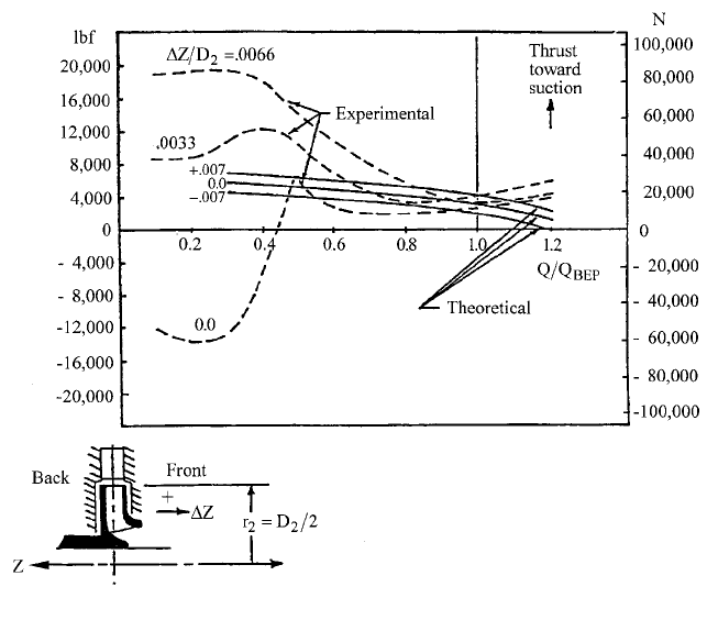
upon further reduction of Q. This effect is clearly seen in the experimental thrust-versus-
Q plots of Figure 34, the impellers having been shifted as just described. Depicted there is
the resulting net load on the axial thrust bearing of an eight-stage, 3600-rpm diffuser
pump that had a cylindrical balancing drum (not a self-compensating balancing disk). The
drum was sized so as not to completely eliminate the thrust
—
in order to avoid thrust
reversals.The solid lines are the predicted net thrust according to the methods outlined in
Table 4 for three axial positions of the impeller. The large excursions in net thrust were
eliminated by restricting the entry of the invading diffuser backflow into the sidewall gaps
—
through a tightening of the gap between the shrouds of impeller and diffuser (Gap “A”)
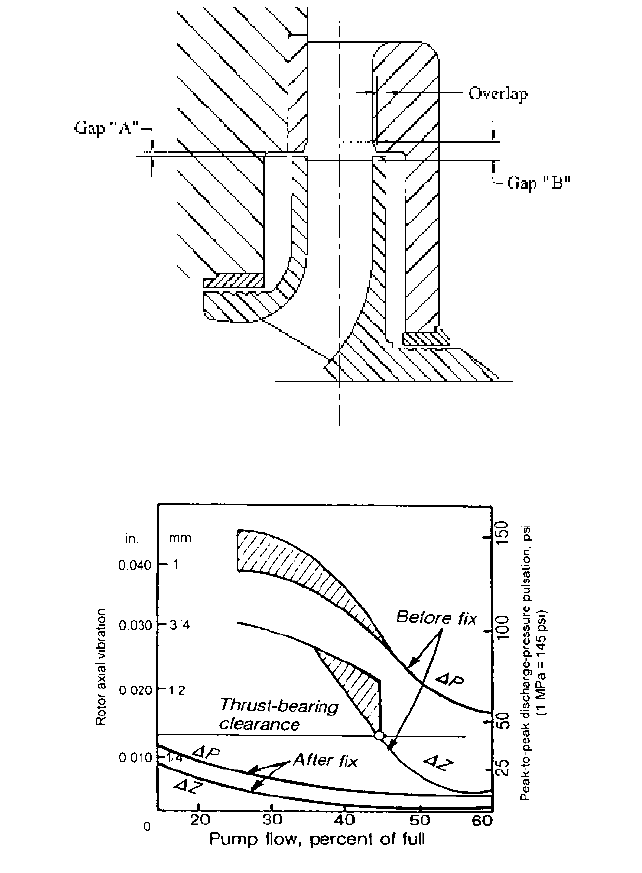
in Figure 35. Gap “A” is not effective unless the “overlap” of the two mating shrouds is from
four to six times the gap dimension
61
. Moreover, if Gap “A” is minimized, this can exagger-
ate the blade-vane interactions, making it necessary to open up Gap “B” more than would
be necessary were Gap “A” not minimized
69
.
A further possibility that has been observed in a single-stage double-suction pump is
the unsteadiness of impeller discharge recirculation and, most likely, of the diffuser or
volute backflow. The side-to-side switching just mentioned appears in Figure 36 to be hap-
pening as a function of time as well as of flow rate Q, as evidenced by the axial motion,
which is accompanied by discharge pressure pulsations. The “fix” mentioned in the figure
was, again, mainly minimizing Gap “A.”
Closing Gap “A” and opening Gap “B” are procedures that have been widely and suc-
cessfully applied in high-energy pumps, which usually work well at BEP but run into dif-
ficulties at low flow
69
. The procedures have proven to cure the thrust and pressure
2.80 CHAPTER 2
FIGURE 34 Axial thrust response to recirculation. (Source: Flowserve Corporation)
pulsation behavior just described and also improve the low-flow performance curve
shape
65
. The results are high-energy pumps that can operate smoothly over a wider range
of flow rate than
—
in many cases
—
was originally expected or specified. Nevertheless, the
higher the energy level, the more intolerable is any unsteadiness and pressure pulsation
activity.
Minimum Flow Limits Because the intensity of pressure pulsations and the accompa-
nying vibrations can increase beyond acceptable limits as flow rate is reduced at constant
speed below the BEP flow, or more specifically, below Q
R
, expressions for how low Q/Q
BEP
can be without exceeding these limits have been developed. Manufacturer and user groups
such as the Hydraulic Institute (HI), the International Standards Organization (ISO), and
the American Petroleum Institute (API) have specified vibration limits that must be met
at what is usually called at the minimum continuous stable flow (MCSF) or simply Q
min
.
In an attempt to answer the question of how far into the recirculation zone (where Q
Q
R
) an operator can take a pump before reaching the MCSF, Gopalakrishnan proposed a
general rationale for computing Q
min
that takes the energy level into account
—
through
the flow rate and rotative speed of the machine
70
. These two quantities imply the blade
tip speed at the inlet of the impeller. (Through typical ratios of impeller OD to eye diam-
eter, this also implies the OD tip speed and therefore the head, the energy level having
been defined in Figure 32 in terms of stage pressure rise p
stg
.) The theory for this method
is defined in Part A of Table 16, in which Q
min
is computed as the product of a series of K-
factors multiplying the value of Q
R
, which is computed according to Fraser’s earlier devel-
opment
67
. Conceptually, the product of these factors approaches unity in the
maximum-energy case, where the instabilities accompanying any recirculation at all are
2.1 CENTRIFUGAL PUMP THEORY 2.81
FIGURE 35 Gaps at impeller periphery
61
FIGURE 36 Eliminating unsteady thrust and pressure pulsations (Source: E. Makay in Power.)
significant. Conceivably, this product could exceed unity at the highest energy levels, as
separation and stall and the attendant unsteadiness must occur
—
as Q is reduced
—
before
the backflows that characterize Q
R
, which was observed by Fraser as the value of flow rate
for the onset of recirculation (see Section 2.3.2).
K
1
and K
3
are given in Table 16 as equations that have been curve-fitted to speed/flow
rate- and NPSH-effect charts that appeared in Gopalakrishnan’s presentation
70
. This
includes the ability to enter any speed (rpm) into the computation for K
1
, only 3500 and