Pump Handbook by Igor J. Karassik, Joseph P. Messina, Paul Cooper, Charles C. Heald - 3rd edition
Подождите немного. Документ загружается.

2.102 CHAPTER TWO
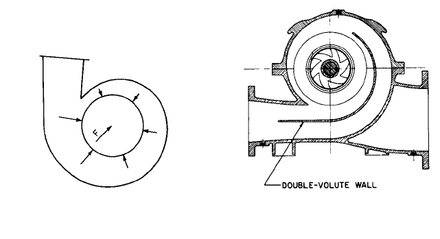
FIGURE 6 At reduced capacities, uniform
pressures do not exist in a single-volute casing,
resulting in a radial reaction F.
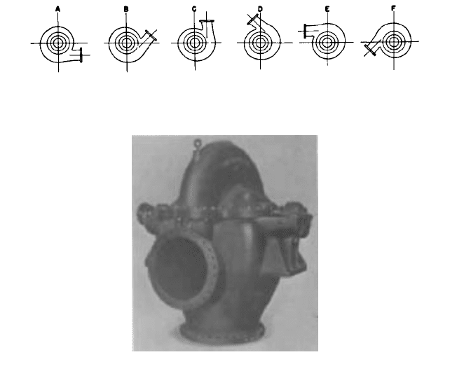
FIGURE 7 Transverse view of a double-volute
casing pump.
forces are approximately equal and opposite. Thus, little if any radial force acts on the
shaft and bearings. Subsection 2.3.1 also covers this topic.
The double-volute design has many hidden advantages. For example, in large-capacity
medium- and high-head single-stage vertical pumps, the rib forming the second volute
that separates it from the discharge waterway of the first volute strengthens the casing
(see Figure 8).
The individual stages of a multistage pump can be made double volute, as illustrated
in Figure 9.The kinetic energy of the pumped liquid discharged from the impeller must be
transformed into pressure energy and then must be turned 180° to enter the impeller of
the next stage.The double volute therefore also acts as a return channel. The back view in
Figure 9 shows this as well as the guide vanes used to straighten the flow into the next
stage. An alternative to the volute design for multistage pumps is the diffuser and its
return vanes that channel the flow from the discharge of the diffuser vanes back into the
impeller of the next stage.
Solid and Split Casings Solid casing implies a design in which the discharge water-
ways leading to the discharge nozzle are all contained in one casting or fabricated piece.
The casing must have one side open so that the impeller can be introduced into it. Because
the sidewalls surrounding the impeller are actually part of the casing, a solid casing,
strictly speaking, cannot be used, and designs normally called solid casing are really radi-
ally split (refer to Figure 1 and see Figures 11, 12, and 13).
A split casing is made of two or more parts fastened together. The term horizontally
split had regularly been used to describe pumps with a casing divided by a horizontal
plane through the shaft centerline or axis (see Figure 10). The term axially split is now
preferred. Because both the suction and discharge nozzles are usually in the same half of
the casing, the other half may be removed for inspection of the interior without disturbing
the bearings or the piping. Like its counterpart horizontally split, the term vertically split
is poor terminology. It refers to a casing split in a plane perpendicular to the axis of rota-
tion. The term radially split is now preferred.
End-Suction Pumps Most end-suction, single-stage pumps are made of one-piece solid
casings. At least one side of the casing must be open so that the impeller can be assem-
bled in the pump.Thus, a cover is required for that side. If the cover is on the suction side,
it becomes the casing sidewall and contains the suction opening (refer to Figure 1). This
is called the suction cover or casing suction head. Other designs are made with casing cov-
ers (see Figure 12) and still others have both casing suction covers and casing covers (refer
to Figure 8 and see Figure 13).
2.2.1 CENTRIFUGAL PUMP: MAJOR COMPONENTS 2.103
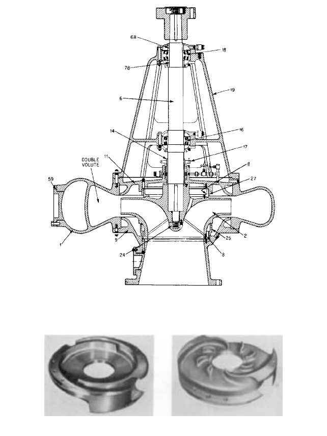
FIGURE 8 The sectional view of a vertical-shaft, end-suction pump with a double-volute casing (the numbers
refer to parts listed in Table 1) (Flowserve Corporation)
FIGURE 9 The double volute of a multistage pump, front view (left) and back view (right) (Flowserve
Corporation)
For general service, the end-suction, single-stage pump design is extensively used for
small pumps with a 4- or 6-in (102 or 152 mm) discharge size for both motor-mounted and
coupled types. In these pumps, the small size makes it feasible to cast the volute and one
side integrally. Whether or not the seal chamber side or the suction side is made integrally
with the casing is usually determined by the most economical pump design.
For larger pumps, especially those for special services such as sewage handling, there
is a demand for pumps of both rotations.A design with separate suction and seal chamber
heads permits the use of the same casing for either rotation if the flanges on the two sides
2.104 CHAPTER TWO
FIGURE 11 End-suction pump with semi-open impeller (Flowserve Corporation)
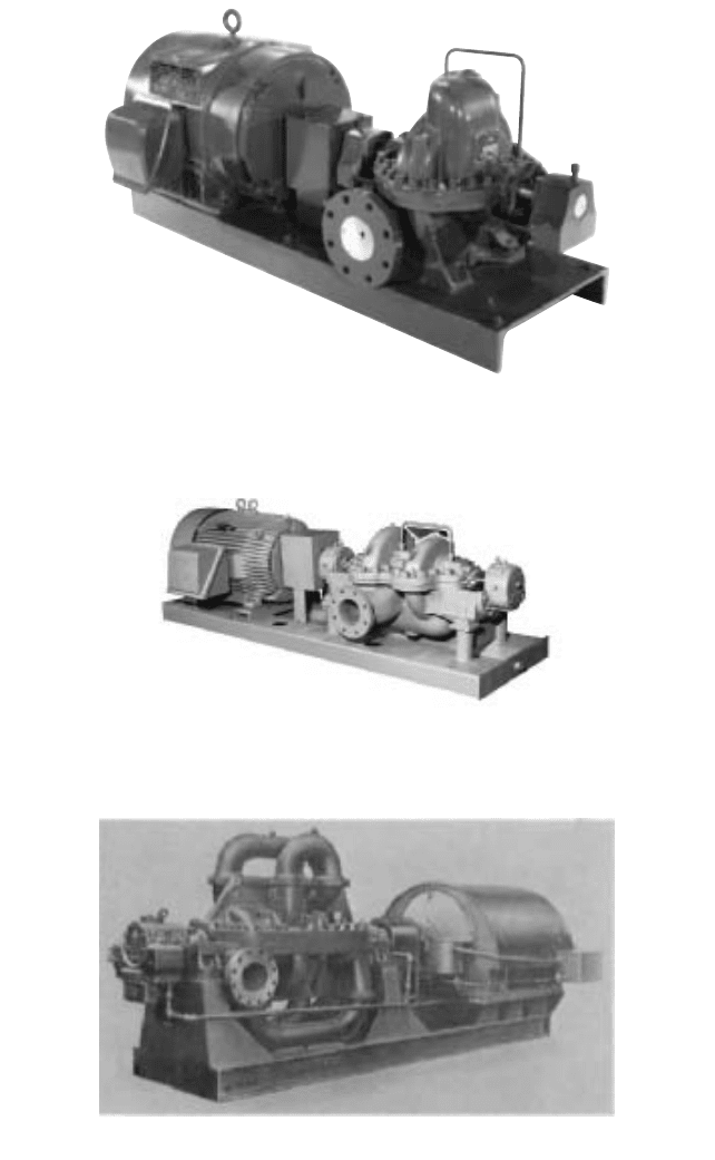
FIGURE 10 An axially split casing, horizontal-shaft, double-suction volute pump (Flowserve Corporation)
are made identical. There is also a demand for vertical pumps that can be disassembled by
removing the rotor and bearing assembly from the top of the casing. Many horizontal
applications of the pumps of the same line, however, require partial dismantling from the
suction side. Such lines are most adaptable when they have separate suction and casing
covers.
Casing Construction for Open- and Semiopen-Impeller Pumps In the open- or
semiopen impeller pump, the impeller rotates within close clearance of the pump casing
or suction cover (refer to Figure 11). If the intended service is abrasive, a side plate is
mounted within the casing to provide a renewable close-clearance guide to the liquid flow-
2.2.1 CENTRIFUGAL PUMP: MAJOR COMPONENTS 2.105
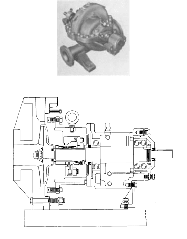
FIGURE 12 End-suction pump with semi-open impeller, inducer and renewable side plate (Flowserve Corporation)
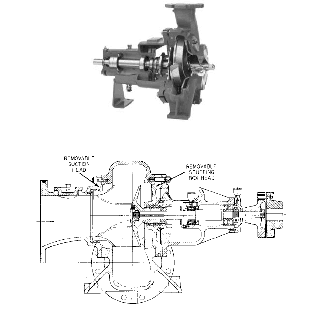
FIGURE 13 End-suction pump with removable suction and stuffing box heads (Flowserve Corporation)
ing through the impeller (refer to Figure 12). One of the advantages of using side plates
is that abrasion-resistant material, such as stainless steel, can be used for the impeller
and side plate, while the casing itself may be of a less costly material. Although double-
suction, semiopen-impeller pumps are seldom used today, they were common in the past
and were generally made with side plates.
In order to maintain pump efficiency, a close running clearance is required between the
front unshrouded face of the open or semiopen impeller and the casing, suction cover, or
side plate. Pump designs provide either jackscrews or shims to adjust the position of the
thrust bearing housing (and, as a result, the axial position of the shaft and impeller) rela-
tive to the bearing frame.
Pre-rotation and Stop Pieces Improper entrance conditions and inadequate suction
approach shapes may cause the liquid column in the suction pipe to spiral for some dis-
tance ahead of the impeller entrance. This phenomenon is called pre-rotation, and it is
attributed to various operational and design factors in both vertical and horizontal pumps.
Pre-rotation is usually harmful to pump operation because the liquid enters between
the impeller vanes at an angle other than that allowed in the design. This frequently low-
ers the net effective suction head and the pump efficiency. Various means are used to avoid
pre-rotation both in the construction of the pump and in the design of the suction
approaches.
2.106 CHAPTER TWO
FIGURE 14 Possible positions of discharge nozzles for a specific design of an end-suction, solid-casing, horizontal-
shaft pump. The rotation illustrated is counterclockwise from suction end.
FIGURE 15 A bottom-suction, axially split casing single-stage pump (Flowserve Corporation)
Practically all horizontal, single-stage, double-suction pumps and most multistage
pumps have a suction volute that guides the liquid in a streamline flow to the impeller eye.
The flow comes to the eye at right angles to the shaft and separates unequally on the two
sides of the shaft. Moving from the suction nozzle to the impeller eye, the suction water-
ways are reduced in area, meeting in a projecting section of the sidewall dividing the two
sections. This dividing projection is called a stop piece. To minimize pre-rotation in end-
suction pumps, a radial-fin stop piece projecting toward the center is sometimes cast into
the suction nozzle wall.
Nozzle Locations The discharge nozzle of end-suction, single-stage horizontal pumps
is usually in a top-vertical position (refer to Figures 1, 11, and 12). However, other nozzle
positions can be obtained, such as top-horizontal, bottom-horizontal, or bottom-vertical.
Figure 14 illustrates the flexibility available in discharge nozzle locations. Sometimes the
pump frame, bearing bracket, or baseplate may interfere with the discharge flange, pro-
hibiting a bottom-horizontal or bottom-vertical discharge nozzle position. In other
instances, solid casings cannot be rotated for various nozzle positions because the seal
chamber connection would become inaccessible.
Practically all double-suction, axially split casing pumps have a side discharge nozzle
and either a side- or a bottom-suction nozzle. If the suction nozzle is placed on the side of
the pump casing with its axial centerline (refer to Figure 10), the pump is classified as a
side-suction pump. If its suction nozzle points vertically downward (see Figure 15), the
pump is called a bottom-suction pump. Single-stage, bottom-suction pumps are rarely
made in sizes below a 10-in (254 mm) discharge nozzle diameter.
Special nozzle positions can sometimes be provided for double-suction, axially split cas-
ing pumps to meet special piping arrangements, such as a radically split casing with bot-
tom suction and top discharge in the same half of the casing. Such special designs are
generally costly and should be avoided.
2.2.1 CENTRIFUGAL PUMP: MAJOR COMPONENTS 2.107
Centrifugal Pump Rotation Because suction and discharge nozzle locations are
affected by pump rotation, it is important to understand how the direction of rotation is
defined. According to Hydraulic Institute standards, rotation is defined as clockwise or
counterclockwise by looking at the driven end of a horizontal pump or looking down on a
vertical pump. To avoid misunderstanding, clockwise or counterclockwise rotation should
always be qualified by including the direction from which one looks at the pump.
The terms inboard end or drive end (the end of the pump closest to the driver) and out-
board end or nondrive end (the end of the pump farthest from the driver) are used only
with horizontal pumps. The terms lose their significance with dual-driven pumps. Any
centrifugal pump casing pattern can be arranged for either clockwise or counterclockwise
rotation, except for end-suction pumps, which have integral heads on one side. These
require separate directional patterns.
Casing Handholes Casing handholes are furnished primarily on pumps handling sewage
and stringy materials that may become lodged on the impeller suction vane edges or on the
tongue of the volute. The holes permit removal of this material without completely disman-
tling the pump. End-suction pumps used primarily for liquids of this type are provided with
handholes or access to the suction side of the impellers. These access points are located on
the suction head or in the suction elbow. Handholes are also provided in drainage, irrigation,
circulating, and supply pumps if foreign matter may become lodged in the waterways. On
very large pumps, manholes provide access to the interior for both cleaning and inspection.
Mechanical Features of Casings Most single-stage centrifugal pumps are intended
for service at moderate pressures and temperatures. As a result, pump manufacturers
usually design a special line of pumps for high operating pressures and temperatures
rather than make their standard line unduly expensive by making it suitable for too wide
a range of operating conditions.
If axially split casings are subject to high pressure, they tend to “breathe” at the split
joint, leading to misalignment of the rotor and, even worse, leakage. For such conditions,
internal and external ribbing is applied to casings at the points subject to the greatest
stress. In addition, whereas most pumps are supported by feet at the bottom of the casing,
high temperatures require centerline support so that, as the pump becomes heated, expan-
sion will not cause misalignment.
Series Units For large-capacity medium-high-head conditions, two single-stage, double-
suction pumps can be connected in a series on one baseplate with a single driver. Such an
arrangement was at one time very common in waterworks applications for heads of 250 to
400 ft (76 to 122 m). One series arrangement uses a double-extended shaft motor in the mid-
dle, driving two pumps connected in a series by external piping. In a second type, a stan-
dard motor is used with one pump having a double-extended shaft.This latter arrangement
may have limited applications because the shaft of the pump next to the motor must be
strong enough to transmit the total pumping horsepower. If the total pressure generated by
such a series unit is relatively high, the casing of the second pump could require ribbing.
Higher heads per stage are becoming more and more common, and series units are gener-
ally used in only very high ranges of total head.
MULTISTAGE PUMP CASINGS__________________________________________
Although the majority of single-stage pumps are of the volute-casing type, both volute and
diffuser casings are used in multistage pump construction. Because a volute casing gives
rise to radial thrust, axially split multistage casings generally have staggered volutes so
that the resultant of the individual radial thrusts is balanced out (see Figures 16 and 17).
Both axially and radially split casings are used for multistage pumps.The choice between
the two designs is dictated by the design pressure, with 2000 lb/in
2
(138 bar)° being typi-
cal for 3600-rpm axially split casing pumps.
°1 bar = 10
5
Pa

2.108 CHAPTER TWO
FIGURE 16 An arrangement of a multistage volute pump for radial-thrust balance
FIGURE 17 The horizontal flange of an axially split casing, six-stage pump (Flowserve Corporation)
Axially Split Casings Regardless of the arrangement of the stages in the casing, it is
necessary to connect the successive stages of a multistage pump. In the low and medium
pressure and capacity ranges, these interstage passages are cast integrally with the cas-
ing proper (see Figures 18 and 19). As the pressures and capacities increase, the desire to
maintain as small a casing diameter as possible, coupled with the necessity of avoiding
sudden changes in the velocity or the direction of the flow, leads to the use of external
interstage passages cast separately from the pump casing. They are formed in the shape
of a loop, bolted or welded to the casing proper (see Figure 20).
Interstage Construction for Axially Split Casing Pumps A multistage pump inher-
ently has adjoining chambers subjected to different pressures, and means must be made
available to isolate these chambers from one another so that the leakage from high to low
pressure will take place only at the clearance joints formed between the stationary and
rotating elements of the pump. Thus, the leakage will be kept to a minimum. The isolating
wall used to separate two adjacent chambers of a multistage pump is called a stage piece,
diaphragm, or inter-stage diaphragm. The stage piece may be formed of a single piece, or it
may be fitted with a renewable stage piece bushing at the clearance joint between the sta-
tionary stage piece and the part of the rotor immediately inside the former. The stage pieces,
which are usually solid, are assembled on the rotor along with impellers, sleeves, bearings,
2.2.1 CENTRIFUGAL PUMP: MAJOR COMPONENTS 2.109
FIGURE 18 Two-stage axially split casing volute pump for small capacities and pressures up to 450 lb/in
2
(31
bar) (Flowserve Corporation)
FIGURE 20 A six-stage, axially split casing volute pump for pressures up to 1,300 lb/in
2
(90 bar) (Flowserve
Corporation)
FIGURE 19 Two-stage axially split casing volute pump for pressures up to 500 lb/in
2
(34 bar) (Flowserve
Corporation
2.110 CHAPTER TWO
and similar components. To prevent the stage pieces from rotating, a locked tongue-and-
groove joint is provided in the lower half of the casing. Clamping the upper casing half to
the lower half securely holds the stage piece and prevents rotation.
The problem of seating a solid stage piece against an axially split casing is one that has
given designers much trouble. First, there is a three-way joint and, second, this seating
must make the joint tight and leakproof under a pressure differential without resorting to
bolting the stage piece directly to the casing.
To overcome this problem, it is wise to make a pump that has a small-diameter casing
so that when the casing bolting is pulled tight, there is a seal fitting of the two casing
halves adjacent to the stage piece.The small diameter likewise helps to eliminate the pos-
sibility of a stage piece cocking and thereby leaving a clearance on the upper-half casing
when it is pulled down. No matter how rigidly the stage piece is located in the lower-half
casing, there must be a sliding fit between the seat face of the stage piece and that in the
upper-half casing so that the upper-half casing can be pulled down. Each stage piece, fur-
thermore, must be arranged so that the pressure differential developed by the pump will
tend to seat the piece tightly against the casing rather than open up the joint.
We have said that axially split casing pumps are typically used for working pressures
of up to 2,000 lb/in
2
(138 bar). High-pressure piping systems, of which these pumps form
a part, are inevitably made of steel because this material has the valuable property of
yielding without breaking. Considerable piping strains are unavoidable, and these strains,
or at least a part thereof, are transmitted to the pump casing. The latter consists essen-
tially of a barrel that is split axially, flanged at the split, and fitted with two necks that
serve as inlet and discharge openings. When piping stresses exist, these necks, being the
weakest part of the casing, are in danger of breaking off if they cannot yield. Steel is there-
fore the safest material for pump casings whenever the working pressures in the pump are
in excess of 1,000 lb/in
2
(70 bar).
This brings up an important feature in the design of the suction and discharge flanges.
Although raised-face flanges are perfectly satisfactory for steel-casing pumps, their use is
extremely dangerous with cast-iron pumps. This danger arises from the lack of elasticity
in cast iron, which leads to flange breakage when the bolts are being tightened, the ful-
crum of the bending moment being located inward from the bolt circle. As a result, it is
essential to avoid raised-face flanges with cast-iron casings as well as the use of a raised-
face flange pipe directly against a flat-face cast-iron pump flange. Suction flanges should
obviously be suitable for whatever hydrostatic test pressure is applied to the pump casing.
The location of the pump casing feet is not critical in smaller pumps operating at dis-
charge pressures below 275 lb/in
2
(19 bar) and at moderate temperatures of up to 300°F
(150°C). Since the unit is relatively small, very little distortion is likely to occur. However,
for larger units operating at higher pressures and temperatures, it is important that the
casing be supported at the horizontal centerline or immediately below the bearings (refer
to Figures 19 and 20).
Radially Split Double-Casing Pumps The oldest form of radially split casing multi-
stage pump is commonly called the ring-section, ring-casing, or the doughnut type. When
more than one stage was found necessary to generate higher pressures, two or more sin-
gle-stage units of the prevalent radially split casing type were assembled and bolted
together.
In later designs, the individual stage sections and separate suction and discharge
heads were held together with large throughbolts. These pumps, still an assembly of
bolted-up sections, can present serious dismantling and reassembly problems because suc-
tion and discharge connections have to be broken each time the pump is serviced. The
double-casing pump retains the advantages of the radially split casing design and mini-
mizes the dismantling problem.
The basic principle consists of enclosing the working parts of a multistage centrifugal
pump in an inner casing and building a second casing around this inner casing.The space
between the two casings is maintained at the discharge pressure of the last pump stage.
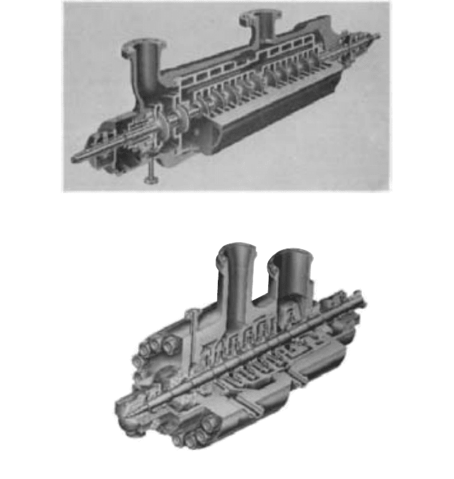
The construction of the inner casing follows one of two basic principles: (1) axial splitting
(see Figure 21) or (2) radial splitting (see Figure 22).
2.2.1 CENTRIFUGAL PUMP: MAJOR COMPONENTS 2.111
FIGURE 21 Double-casing multistage pump with axially split inner casing (Allis-Chalmers)
FIGURE 22 Double-casing multistage pump with radially split inner casing (Flowserve Corporation)
The double-casing pump with radially split inner casing is an evolution of the ring-
casing pump with added provisions to ease dismantling. The inner unit is generally con-
structed exactly as a ring-casing pump. After assembly, it is inserted and bolted inside a
cylindrical casing that supports it and leaves it free to expand under temperature changes.
In Figure 23, the inner assembly of such a pump is being inserted into the outer casing.
Figure 24 shows the external appearance of this type of pump. The suction and discharge
nozzles form an integral part of the outer casing, and the internal assembly of the pump
can be withdrawn without disturbing the piping connections.
Hydrostatic Pressure Tests It is standard practice for the manufacturer to conduct
hydrostatic tests for the parts of a pump that contain fluid under pressure. This means
that the pump casing and, where applicable, parts like suction or casing covers are assem-
bled with the internal parts, removed, and are then subjected to a hydrostatic test, gen-
erally for a minimum of 30 minutes. Such a test demonstrates that the casing containment
is sound and that there is no leakage of fluid to the exterior.
Additional tests may be conducted by the pump manufacturer to determine the
soundness of internal partitions separating areas of the pump operating under different
pressures.