Pump Handbook by Igor J. Karassik, Joseph P. Messina, Paul Cooper, Charles C. Heald - 3rd edition
Подождите немного. Документ загружается.

2.112 CHAPTER TWO
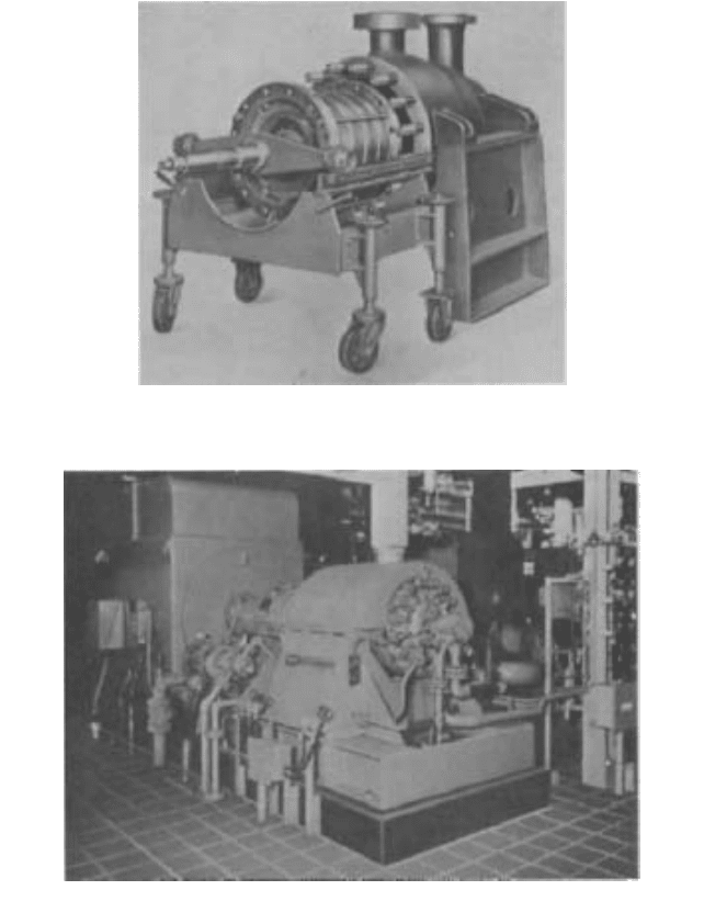
FIGURE 23 Rotor assembly of a radially split, double-casing pump being inserted into its outer casing
(Flowserve Corporation)
FIGURE 24 Multistage radially split, double-casing pump (Flowserve Corporation)
The definition of the applicable hydrostatic pressure for these tests varies. The most
generally accepted definition is that given by the Hydraulic Institute Standards. Each part
of the pump that contains fluid under pressure shall be capable of withstanding a hydro-
static test at not less than the greatest of the following:
• 150 percent of the pressure that will occur in that part when the pump is operated at
rated conditions for the given application of the pump, except thermoset parts
• 125 percent of the pressure that would occur in that part when the pump is operating
at rated speed for a given application, but with the pump discharge valve closed

2.2.1 CENTRIFUGAL PUMP: MAJOR COMPONENTS 2.113
FIGURE 25 Straight-vane, radial, single-suction closed impeller (Flowserve Corporation)
IMPELLERS _________________________________________________________
In a single-suction impeller, the liquid enters the suction eye on one side only. A double-
suction impeller is, in effect, two single-suction impellers arranged back to back in a sin-
gle casing. The liquid enters the impeller simultaneously from both sides, while the two
casing suction passageways are connected to a common suction passage and a single suc-
tion nozzle.
For the general service single-stage, axially split casing design, a double-suction
impeller is favored because it is theoretically in an axial hydraulic balance and because
the greater suction area of a double-suction impeller permits the pump to operate with
less net absolute suction head. For small units, the single-suction impeller is more prac-
tical for manufacturing reasons, as the waterways are not divided into two very narrow
passages. It is also sometimes preferred for structural reasons. End-suction pumps with
single-suction overhung impellers have both first-cost and maintenance advantages
unobtainable with double-suction impellers. Most radially split casing pumps therefore
use single-suction impellers. Because an overhung impeller does not require the exten-
sion of a shaft into the impeller suction eye, single-suction impellers are preferred for
pumps handling suspended matter, such as sewage. In multistage pumps, single-suction
impellers are almost universally used because of the design and first-cost complexity that
double-suction staging introduces.
Impellers are called radial vane or radial flow when the liquid pumped is made to dis-
charge radially to the periphery. Impellers of this type usually have a specific speed below
4200 (2600) if single-suction and below 6000 (3700) if double-suction. Specific speed is dis-
cussed in detail in Subsection 2.3.1. The units for specific speed used here are in USCS
rpm, gallons per minute, and feet. In SI, they are rpm, liters per second, and meters.
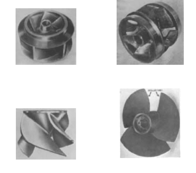
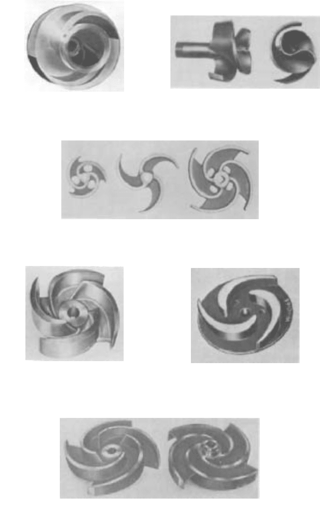
Impellers can also be classified by the shape and form of their vanes:
• The straight-vane impeller (see Figures 25, 34, 35, 36, and 37)
• The Francis-vane or screw-vane impeller (see Figures 26 and 27)
• The mixed-flow impeller (see Figure 28)
• The propeller or axial-flow impeller (see Figure 29)
In a straight-vane radial impeller, the vane surfaces are generated by straight lines
parallel to the axis of rotation. These are also called single-curvature vanes. The vane sur-
faces of a Francis-vane radial impeller have a double curvature. An impeller design that
has both a radial-flow and an axial-flow component is called a mixed-flow impeller. It is
generally restricted to single-suction designs with a specific speed above 4200 (2600).
Types with lower specific speeds are called Francis-vane impellers. Mixed-flow impellers
with a small radial-flow component are usually referred to as propellers. In a true pro-
peller, or axial-flow impeller, the flow strictly parallels the axis of rotation. In other words,
it moves only axially.
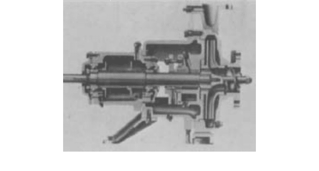
An inducer is a low-head, axial-flow impeller with few blades that is placed in front of
a conventional impeller. The hydraulic characteristics of an inducer are such that it
requires considerably less NPSH than a conventional impeller. Both inducer and impeller
2.114 CHAPTER TWO
FIGURE 26 Francis-vane, radial, double-suction
closed impeller (Flowserve Corporation)
FIGURE 27 High-specific-speed, Francis-vane,
radial, double-suction closed impeller (Flowserve
Corporation)
FIGURE 28 Open mixed-flow impeller (Flowserve
Corporation)
FIGURE 29 Axial-flow impeller (Flowserve
Corporation)
are mounted on the same shaft and rotate at the same speed (see Figure 30). The main
purpose of the inducer is not to generate an appreciable portion of the total pump head,
but to increase the suction pressure to a conventional impeller. Inducers are therefore used
to reduce the NPSH requirements of a given pump or to permit the pump to operate at
higher speeds with a given available NPSH. For a further discussion of inducers, see Sec-
tion 2.1 and Subsection 2.3.1.
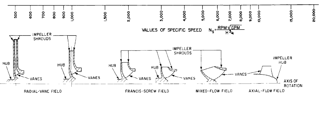
The relation of single-suction impeller profiles to specific speed is shown in Figure 31.
The classification of impellers according to their vane shape is naturally arbitrary inas-
much as there is much overlapping in the types of impellers used in the different types of
pumps. For example, impellers in single- and double-suction pumps of low specific speeds
have vanes extending across the suction eye. This provides a mixed flow at the impeller
entrance for low pickup losses at high rotative speeds but enables the discharge portion of
the impeller to use the straight-vane principle. In pumps of higher specific speed operat-
ing against low beads, impellers have double-curvature vanes extending over the full vane
surface.They are therefore full Francis-type impellers. The mixed-flow impeller, usually a
single-suction type, is essentially one-half of a double-suction, high-specific-speed, Francis-
vane impeller.
In addition, many impellers are designed for specific applications. For instance, the
conventional impeller design with sharp vane edges and restricted areas is not suitable for
handling liquids containing rags, stringy materials, and solids like sewage because it will
become clogged. Special nonclogging impellers with blunt edges and large waterways have
been developed for such services (see Figure 32). For pumps up to the 12- to 16-in (305- to
406-mm) discharge size, these impellers have only two vanes. Larger pumps normally use
three or four vanes.
2.2.1 CENTRIFUGAL PUMP: MAJOR COMPONENTS 2.115
FIGURE 30 A centrifugal pump with a conventional impeller preceded by an inducer (Flowserve Corporation)
Another impeller design used for paper pulp pumps (see Figure 33) is fully open and
nonclogging; it has screw and radial streamlined vanes.The screw-conveyor end projects far
into the suction nozzle, permitting the pump to handle high-consistency paper pulp stock.
Impeller Mechanical Types Mechanical design also determines impeller classification.
Accordingly, impellers may be completely open, semiopen, or closed.
Strictly speaking, an open impeller (see Figures 34 and 35) consists of nothing but
vanes attached to a central hub for mounting on the shaft without any form of sidewall or
shroud. The disadvantage of this impeller is structural weakness. If the vanes are long,
they must be strengthened by ribs or a partial shroud. Generally, open impellers are used
in small, low energy pumps. One advantage of open impellers is that they are better suited
for handling liquids containing stringy materials. It is also sometimes claimed that they
are better suited for handling liquids containing suspended matter because the solids in
such matter are more likely to be clogged in the space between the rotating shrouds of a
closed impeller and the stationary casing walls. It has been demonstrated, however, that
closed impellers do not clog easily, thus disproving the claim for the superiority of the
open-impeller design. In addition, the open impeller is much more sensitive to wear than
the closed impeller and therefore its efficiency may deteriorate rather rapidly.
The open impeller rotates between two side plates, between the casing walls of the
volute, or between the casing cover and the suction head. The clearance between the
impeller vanes and the sidewalls enables a certain amount of water slippage.This slippage
increases as wear increases. To restore the original efficiency, both the impeller and the
side plate(s) must be replaced. This, incidentally, involves a much larger expense than
would be entailed in closed impeller pumps where simple rings form the leakage joint.
The semiopen impeller (see Figure 36) incorporates a single shroud, usually at the back
of the impeller. This shroud may or may not have pump-out vanes, which are vanes located
at the back of the impeller shroud (see Figure 37).This function reduces the pressure at the
back hub of the impeller and prevents foreign matter from lodging in back of the impeller
that would interfere with the proper operation of the pump and the seal chamber.
The closed impeller (refer to Figures 25 through 27), which is almost universally used
in centrifugal pumps handling clear liquids, incorporates shrouds or sidewalls that totally
enclose the impeller waterways from the suction eye to the periphery. Although this design
prevents the liquid slippage that occurs between an open or semiopen impeller and its side
plates, a running joint must be provided between the impeller and the casing to separate
the discharge and suction chambers of the pump. This running joint is usually formed by
a relatively short cylindrical surface on the impeller shroud that rotates within a slightly
larger stationary cylindrical surface. If one or both surfaces are made renewable, the leak-
age joint can be repaired when wear causes excessive leakage.
2.116
FIGURE 31 Variations in impeller profiles with specific speeds and approximate ranges of specific speeds for the various types
. [Universal specific speed
s
= N
s
/2733. N
q
(in rpm,
m
3
/s, m) = N
s
/51.65].
2.2.1 CENTRIFUGAL PUMP: MAJOR COMPONENTS 2.117
FIGURE 32 Phantom view of a radial-vane
nonclogging impeller (Flowserve Corporation)
FIGURE 33 Paper plup impeller (Flowserve
Corporation)
FIGURE 35 An open impeller with partial shroud
(Flowserve Corporation)
FIGURE 36 Semiopen impeller (Flowserve
Corporation)
FIGURE 37 The front and back views of an open impeller with a partial shroud and pump-out vanes on the back
side (Flowserve Corporation)
FIGURE 34 Open impellers. Notice that the impellers at left and right are strengthened by a partial shroud
(Flowserve Corporation).
2.118 CHAPTER TWO
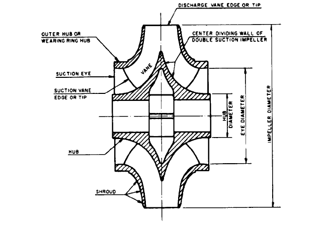
FIGURE 38 Parts of a double-suction impeller
If the pump shaft terminates at the impeller so that the latter is supported by bearings
on one side, the impeller is called an overhung impeller. This type of construction is the
best for end-suction pumps with single-suction impellers.
Impeller Nomenclature The inlet of an impeller just before the section where the vanes
begin is called the suction eye (see Figure 38). In a closed-impeller pump, the suction eye
diameter is taken as the smallest inside diameter of the shroud. In determining the area
of the suction eye, the area occupied by the impeller shaft hub is deducted.
The hub is the central part of the impeller that is bored out to receive the pump shaft.
The term, however, is also frequently used for the part of the impeller that rotates in the
casing fit or in the casing wearing ring. It is then referred to as the outer impeller hub or
the wearing-ring hub of the shroud.
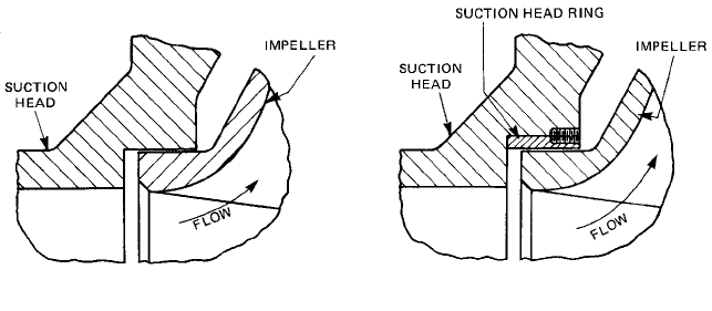
WEARING RINGS ____________________________________________________
Wearing rings provide an easily and economically renewable leakage joint between the
impeller and the casing. A leakage joint without renewable parts is illustrated in Figure
39. To restore the original clearances of such a joint after wear occurs, the user must either
(1) build up the worn surfaces by welding or metal spraying, or (2) buy new parts.
The new parts are not very costly in small pumps, especially if the stationary casing
element is a simple suction cover. This is not true for larger pumps or where the station-
ary element of the leakage joint is part of a complicated casting. If the first cost of a pump
is of prime importance, it is more economical to provide for remachining both the station-
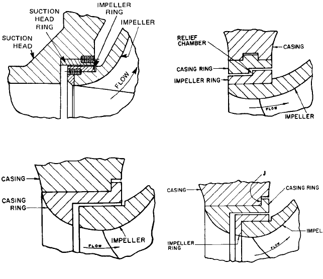
ary parts and the impeller. Renewable casing and impeller rings can then be installed (see
Figures 40, 41, and 42). The nomenclature for the casing or stationary part forming the
leakage joint surface is as follows: (1) casing ring (if mounted in the casing), (2) casing ring
or suction head ring (if mounted in a suction cover or head), and (3) casing cover ring or
head ring (if mounted in the casing cover or head). Some engineers like to identify the part
2.2.1 CENTRIFUGAL PUMP: MAJOR COMPONENTS 2.119
FIGURE 39 A plain flat leakage joint with no rings
further by adding the word wearing, such as casing wearing ring. A renewable part for the
impeller wearing surface is called the impeller ring. Pumps with both stationary and
rotating rings are said to have double-ring construction.
Wearing Ring Types Various types of wearing ring designs, and the selection of the
most desirable type depends on the liquid being handled, the pressure differential across
the leakage joint, the rubbing speed, and the particular pump design. In general, cen-
trifugal pump designers use the ring construction that they have found to be most suit-
able for each particular pump service.
The most common ring constructions are the flat type (see Figures 40 and 41) and the
L type. The leakage joint in the former is a straight, annular clearance. In the L-type ring
(see Figure 43), the axial clearance between the impeller and the casing ring is large, so the
velocity of the liquid flowing into the stream entering the suction eye of the impeller is low.
The L-type casing rings shown in Figures 43 and 44 have the additional function of guid-
ing the liquid into the impeller eye; they are called nozzle rings. Impeller rings of the L type
shown in Figure 44 also furnish protection for the face of the impeller wearing ring hub.
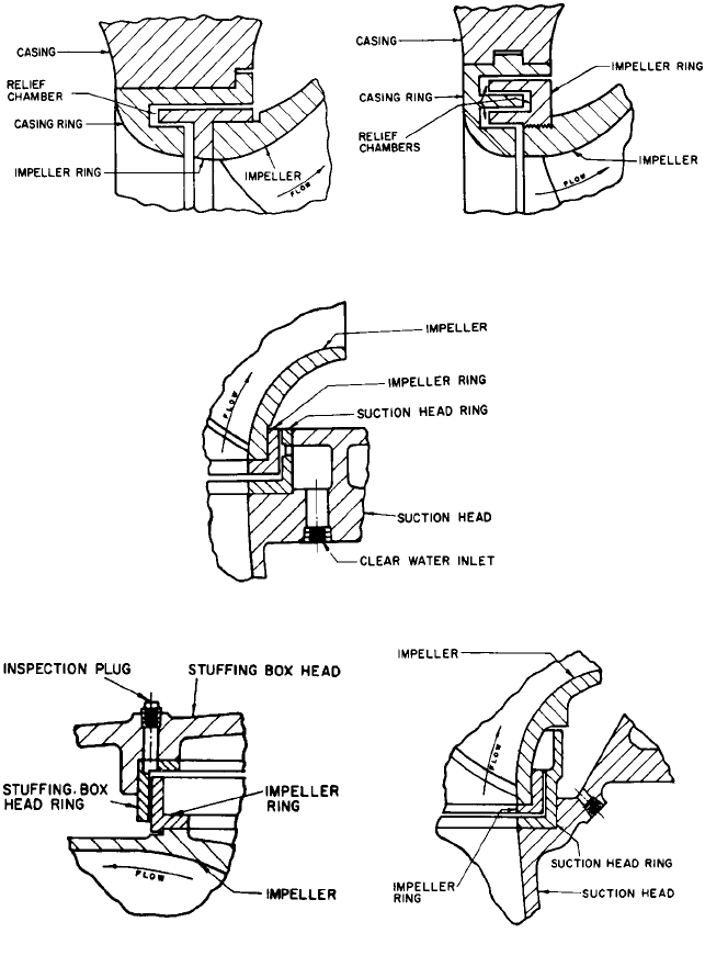
Some designers favor labyrinth-type rings (see Figures 45 and 46) that have two or
more annular leakage joints connected by relief chambers. In leakage joints involving a
single unbroken path, the flow is a function of both the area and the length of the joint as
well as of the pressure differential across the joint. If the path is broken by relief chambers
(see to Figure 42, 45, and 46), the velocity energy in the jet is dissipated in each relief cham-
ber, increasing the resistance. As a result, with several relief chambers and several leak-
age joints for the same actual flow through the joint, the area and hence the clearance
between the rings can be greater than for an unbroken, shorter leakage joint.
The single labyrinth ring with only one relief chamber (refer to Figure 45) is often
called an intermeshing ring. The step-ring type (refer to Figure 42) utilizes two flat-ring
elements of slightly different diameters over the total leakage joint width with a relief
chamber between the two elements. Other ring designs also use some form of relief cham-
ber. For example, one commonly used in small pumps has a flat joint similar to that in Fig-
ure 40, but with one surface broken by a number of grooves. These act as relief chambers
to dissipate the jet velocity head, thereby increasing the resistance through the joint and
decreasing the leakage.
For raw water pumps in waterworks service and for larger pumps in sewage services
in which the liquid contains sand and grit, water-flushed rings have been used (see Figure
47). Clear water under a pressure greater than that on the discharge side of the rings is
piped to the inlet and distributed by the cored passage, the holes through the stationary
ring, and the groove to the leakage joint. Ideally, the clear water should fill the leakage
joint with some flow to the suction and discharge sides to prevent any sand or grit from
getting into the clearance space. Wearing-ring flush is also employed in some process
pumps when pumping solids or abrasives to minimize ring wear by injecting a compatible
clean liquid between the rings.
FIGURE 40 A single flat casing ring construction.
2.120 CHAPTER TWO
FIGURE 41 A double flat ring construction
FIGURE 42 A step-type leakage joint with double
rings
FIGURE 43 An L-type nozzle casing ring
FIGURE 44 Double rings, both of L type
In large pumps (with roughly a 36-in [900-mm] or larger discharge size), particularly
vertical, end-suction, single-stage volute pumps, size alone permits some refinements not
found in smaller pumps. One example is the inclusion of inspection ports for measuring
ring clearance (see Figure 48).These ports can be used to check the impeller centering after
the original installation as well as to observe ring wear without dismantling the pump.
The lower rings of large vertical pumps handling liquids containing sand and grit in
intermittent services are highly susceptible to wear. During shutdown periods, the grit
and sand settle out and naturally accumulate in the region where these rings are
installed, as it is the lowest point on the discharge side of the pump. When the pump is
started again, this foreign matter is washed into the joint all at once and causes wear. To
prevent this action in medium and large pumps, a dam-type ring is often used (see Figure
49). Periodically, the pocket on the discharge side of the dam can be flushed out.
One problem with the simple water-flushed ring is the failure to get uniform pressure
in the stationary ring groove. If pump size and design permit, two sets of wearing rings
arranged in tandem and separated by a large water space (see Figure 50) provide the best
solution. The large water space enables a uniform distribution of the flushing water to the
full 360° degrees of each leakage joint. Because ring 2 is shorter and because a greater
clearance is used there than at ring 1, equal flow can take place to the discharge pressure
side and to the suction pressure side.This design also makes it easier to harden or coat the
surfaces.
For pumps handling gritty or sandy water, the ring construction should provide an
apron on which the stream leaving the leakage joint can impinge, as sand or grit in the jet
will erode any surface it hits. Thus, a form of L-type casing ring similar to that shown in
Figure 49 should be used.
2.2.1 CENTRIFUGAL PUMP: MAJOR COMPONENTS 2.121
FIGURE 45 A single-labyrinth, intermeshing type.
It is a double-ring construction with a nozzle-type
casing ring.
FIGURE 46 Labyrinth-type rings in a double-ring
construction
FIGURE 47 Water-flushed wearing ring
FIGURE 48 Wearing ring with an inspection port for
checking clearance
FIGURE 49 Dam-type ring construction
Wearing-Ring Location In some designs, leakage is controlled by an axial clearance
(see Figure 51). Generally, this design requires a means of adjusting the shaft position for
proper clearance. Then, if uniform wear occurs over the two surfaces, the original clear-
ance can be restored by adjusting the position of the impeller. A limit exists to the amount
of wear that can be compensated, because the impeller must be nearly central in the cas-
ing waterways.